EP1644645B1 - Fernsteuerung für schwere baumaschinen mit kolbenstangenstössel - Google Patents
Fernsteuerung für schwere baumaschinen mit kolbenstangenstössel Download PDFInfo
- Publication number
- EP1644645B1 EP1644645B1 EP04767450A EP04767450A EP1644645B1 EP 1644645 B1 EP1644645 B1 EP 1644645B1 EP 04767450 A EP04767450 A EP 04767450A EP 04767450 A EP04767450 A EP 04767450A EP 1644645 B1 EP1644645 B1 EP 1644645B1
- Authority
- EP
- European Patent Office
- Prior art keywords
- push rod
- head
- remote control
- cavity
- pusher
- Prior art date
- Legal status (The legal status is an assumption and is not a legal conclusion. Google has not performed a legal analysis and makes no representation as to the accuracy of the status listed.)
- Expired - Lifetime
Links
- 238000010276 construction Methods 0.000 title 1
- 238000001514 detection method Methods 0.000 claims abstract description 13
- 230000006835 compression Effects 0.000 claims description 34
- 238000007906 compression Methods 0.000 claims description 34
- 230000005355 Hall effect Effects 0.000 claims description 7
- 230000002093 peripheral effect Effects 0.000 claims description 5
- 230000000284 resting effect Effects 0.000 claims description 5
- 239000011347 resin Substances 0.000 claims description 4
- 229920005989 resin Polymers 0.000 claims description 4
- 230000001154 acute effect Effects 0.000 claims description 3
- 238000007599 discharging Methods 0.000 claims 2
- 230000000630 rising effect Effects 0.000 claims 2
- 230000001174 ascending effect Effects 0.000 abstract 1
- 230000000994 depressogenic effect Effects 0.000 description 33
- 238000006073 displacement reaction Methods 0.000 description 6
- 208000031968 Cadaver Diseases 0.000 description 5
- 210000004027 cell Anatomy 0.000 description 2
- 239000000463 material Substances 0.000 description 2
- 210000000056 organ Anatomy 0.000 description 2
- 239000000470 constituent Substances 0.000 description 1
- 230000003247 decreasing effect Effects 0.000 description 1
- 230000000694 effects Effects 0.000 description 1
- 239000012530 fluid Substances 0.000 description 1
- 238000012986 modification Methods 0.000 description 1
- 230000004048 modification Effects 0.000 description 1
Images


Classifications
-
- F—MECHANICAL ENGINEERING; LIGHTING; HEATING; WEAPONS; BLASTING
- F15—FLUID-PRESSURE ACTUATORS; HYDRAULICS OR PNEUMATICS IN GENERAL
- F15B—SYSTEMS ACTING BY MEANS OF FLUIDS IN GENERAL; FLUID-PRESSURE ACTUATORS, e.g. SERVOMOTORS; DETAILS OF FLUID-PRESSURE SYSTEMS, NOT OTHERWISE PROVIDED FOR
- F15B13/00—Details of servomotor systems ; Valves for servomotor systems
- F15B13/02—Fluid distribution or supply devices characterised by their adaptation to the control of servomotors
- F15B13/04—Fluid distribution or supply devices characterised by their adaptation to the control of servomotors for use with a single servomotor
- F15B13/042—Fluid distribution or supply devices characterised by their adaptation to the control of servomotors for use with a single servomotor operated by fluid pressure
-
- F—MECHANICAL ENGINEERING; LIGHTING; HEATING; WEAPONS; BLASTING
- F15—FLUID-PRESSURE ACTUATORS; HYDRAULICS OR PNEUMATICS IN GENERAL
- F15B—SYSTEMS ACTING BY MEANS OF FLUIDS IN GENERAL; FLUID-PRESSURE ACTUATORS, e.g. SERVOMOTORS; DETAILS OF FLUID-PRESSURE SYSTEMS, NOT OTHERWISE PROVIDED FOR
- F15B13/00—Details of servomotor systems ; Valves for servomotor systems
- F15B13/02—Fluid distribution or supply devices characterised by their adaptation to the control of servomotors
- F15B13/04—Fluid distribution or supply devices characterised by their adaptation to the control of servomotors for use with a single servomotor
- F15B13/042—Fluid distribution or supply devices characterised by their adaptation to the control of servomotors for use with a single servomotor operated by fluid pressure
- F15B13/0422—Fluid distribution or supply devices characterised by their adaptation to the control of servomotors for use with a single servomotor operated by fluid pressure with manually-operated pilot valves, e.g. joysticks
-
- F—MECHANICAL ENGINEERING; LIGHTING; HEATING; WEAPONS; BLASTING
- F15—FLUID-PRESSURE ACTUATORS; HYDRAULICS OR PNEUMATICS IN GENERAL
- F15B—SYSTEMS ACTING BY MEANS OF FLUIDS IN GENERAL; FLUID-PRESSURE ACTUATORS, e.g. SERVOMOTORS; DETAILS OF FLUID-PRESSURE SYSTEMS, NOT OTHERWISE PROVIDED FOR
- F15B13/00—Details of servomotor systems ; Valves for servomotor systems
-
- F—MECHANICAL ENGINEERING; LIGHTING; HEATING; WEAPONS; BLASTING
- F15—FLUID-PRESSURE ACTUATORS; HYDRAULICS OR PNEUMATICS IN GENERAL
- F15B—SYSTEMS ACTING BY MEANS OF FLUIDS IN GENERAL; FLUID-PRESSURE ACTUATORS, e.g. SERVOMOTORS; DETAILS OF FLUID-PRESSURE SYSTEMS, NOT OTHERWISE PROVIDED FOR
- F15B13/00—Details of servomotor systems ; Valves for servomotor systems
- F15B13/02—Fluid distribution or supply devices characterised by their adaptation to the control of servomotors
- F15B13/04—Fluid distribution or supply devices characterised by their adaptation to the control of servomotors for use with a single servomotor
-
- F—MECHANICAL ENGINEERING; LIGHTING; HEATING; WEAPONS; BLASTING
- F15—FLUID-PRESSURE ACTUATORS; HYDRAULICS OR PNEUMATICS IN GENERAL
- F15B—SYSTEMS ACTING BY MEANS OF FLUIDS IN GENERAL; FLUID-PRESSURE ACTUATORS, e.g. SERVOMOTORS; DETAILS OF FLUID-PRESSURE SYSTEMS, NOT OTHERWISE PROVIDED FOR
- F15B13/00—Details of servomotor systems ; Valves for servomotor systems
- F15B13/02—Fluid distribution or supply devices characterised by their adaptation to the control of servomotors
- F15B13/04—Fluid distribution or supply devices characterised by their adaptation to the control of servomotors for use with a single servomotor
- F15B13/0401—Valve members; Fluid interconnections therefor
- F15B2013/0409—Position sensing or feedback of the valve member
-
- Y—GENERAL TAGGING OF NEW TECHNOLOGICAL DEVELOPMENTS; GENERAL TAGGING OF CROSS-SECTIONAL TECHNOLOGIES SPANNING OVER SEVERAL SECTIONS OF THE IPC; TECHNICAL SUBJECTS COVERED BY FORMER USPC CROSS-REFERENCE ART COLLECTIONS [XRACs] AND DIGESTS
- Y10—TECHNICAL SUBJECTS COVERED BY FORMER USPC
- Y10T—TECHNICAL SUBJECTS COVERED BY FORMER US CLASSIFICATION
- Y10T137/00—Fluid handling
- Y10T137/8158—With indicator, register, recorder, alarm or inspection means
- Y10T137/8225—Position or extent of motion indicator
- Y10T137/8242—Electrical
-
- Y—GENERAL TAGGING OF NEW TECHNOLOGICAL DEVELOPMENTS; GENERAL TAGGING OF CROSS-SECTIONAL TECHNOLOGIES SPANNING OVER SEVERAL SECTIONS OF THE IPC; TECHNICAL SUBJECTS COVERED BY FORMER USPC CROSS-REFERENCE ART COLLECTIONS [XRACs] AND DIGESTS
- Y10—TECHNICAL SUBJECTS COVERED BY FORMER USPC
- Y10T—TECHNICAL SUBJECTS COVERED BY FORMER US CLASSIFICATION
- Y10T137/00—Fluid handling
- Y10T137/8158—With indicator, register, recorder, alarm or inspection means
- Y10T137/8225—Position or extent of motion indicator
- Y10T137/8275—Indicator element rigidly carried by the movable element whose position is indicated
-
- Y—GENERAL TAGGING OF NEW TECHNOLOGICAL DEVELOPMENTS; GENERAL TAGGING OF CROSS-SECTIONAL TECHNOLOGIES SPANNING OVER SEVERAL SECTIONS OF THE IPC; TECHNICAL SUBJECTS COVERED BY FORMER USPC CROSS-REFERENCE ART COLLECTIONS [XRACs] AND DIGESTS
- Y10—TECHNICAL SUBJECTS COVERED BY FORMER USPC
- Y10T—TECHNICAL SUBJECTS COVERED BY FORMER US CLASSIFICATION
- Y10T137/00—Fluid handling
- Y10T137/8593—Systems
- Y10T137/87056—With selective motion for plural valve actuator
- Y10T137/87064—Oppositely movable cam surfaces
-
- Y—GENERAL TAGGING OF NEW TECHNOLOGICAL DEVELOPMENTS; GENERAL TAGGING OF CROSS-SECTIONAL TECHNOLOGIES SPANNING OVER SEVERAL SECTIONS OF THE IPC; TECHNICAL SUBJECTS COVERED BY FORMER USPC CROSS-REFERENCE ART COLLECTIONS [XRACs] AND DIGESTS
- Y10—TECHNICAL SUBJECTS COVERED BY FORMER USPC
- Y10T—TECHNICAL SUBJECTS COVERED BY FORMER US CLASSIFICATION
- Y10T137/00—Fluid handling
- Y10T137/8593—Systems
- Y10T137/87056—With selective motion for plural valve actuator
- Y10T137/87072—Rotation about either of two pivotal axes
Definitions
- the present invention relates to the technical field of remote controls for public works machinery, including so-called electro-hydraulic remote controls.
- the invention relates more particularly to remote controls which are intended to allow the control of one or more receiving members, in particular users of fluid under pressure, from a handle operated by the operator to transmit a control signal to said organs. hydraulic receivers.
- the present invention therefore aims to overcome the aforementioned drawbacks by providing a remote control whose number of component parts is reduced while maintaining the same functionality.
- the remote control of the aforementioned type is essentially characterized in that at least the head of the first pusher is further movable to an extended position which is opposite the depressed position relative to said rest position , in that first elastic return means urge the pusher head towards its extended position, so that at least the head of the first pusher has an autonomous upward movement to follow the skirt when the handle is tilted, and in that the remote control further comprises detection means for detecting any position occupied by the head of the first pusher between its output and depressed positions.
- the detection means are of the type without mechanical contact.
- the detection means comprise a magnet which is integral in movement with the pusher head.
- the cavity is stepped and comprises a first shoulder substantially transverse to the displacement of the first pusher
- said pusher comprises an intermediate portion which is integral in movement with the head and the foot of the pusher, which is located between its head and its foot, and delimiting an upper stop and a lower stop, the upper abutment bearing against the first shoulder in the extended position of the pusher and the lower abutment bearing against the bottom of the cavity in the depressed position of said pusher.
- the first return means are housed in the cavity.
- the first return means comprise a flange carried by the intermediate section in the vicinity of the upper stop, and a first compression spring interposed between the flange and the bottom of the cavity.
- the cavity comprises a shoulder substantially transverse to the displacement of the first pusher
- said pusher comprises a head and a foot integral in motion and movable in translation along the axis of the pusher relative to an intermediate section, which is located between the head and the foot, and which delimits a high stop and a low stop, the high stop abutting against the shoulder when the head of the pusher is between its rest position and its extended position and the bottom stop bearing against the bottom of the cavity in the depressed position of said pusher.
- the first elastic return means are housed between the pusher head and the intermediate portion of the pusher.
- the first elastic return means comprise a first compression spring interposed between the pusher head and the intermediate portion of the pusher.
- second elastic return means are housed in the cavity to return the first pusher from its depressed position to its rest position.
- the second return means comprise a ring concentric with the first pusher, a second compression spring which is interposed between the ring and the bottom of the cavity, and a peripheral relief integral with the first pusher and intended to come resting on the ring, the cavity further comprising a second shoulder on which the ring abuts in the rest position of the first pusher.
- the second return means comprise a collar carried by the intermediate section in the vicinity of the upper stop, and a second compression spring interposed between the collar and the bottom of the cavity.
- a second pusher is mounted in a second cavity of the body, the second pusher being resiliently biased by a third compression spring so that the force exerted on the handle to drive one of the first and second pusher is substantially constant.
- the second cavity is symmetrical with the first cavity relative to the axis of the handle in the rest position.
- At least the head of the second pusher is movable to an extended position which is opposed to the depressed position relative to said rest position and elastic return means urge the head of the pushing to its extended position, so that at least the head of the second pusher has an autonomous upward movement.
- the foot of the first pusher is mounted through the bottom of the cavity and internally carries the magnet.
- a Hall effect sensor is mounted in the body of the remote control, facing the movement of the magnet between the depressed and output positions of the first pusher.
- the second pusher is located opposite the first pusher relative to the axis of the handle.
- the Hall effect sensor is embedded in the resin to be placed in a sealed region.
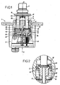
- the figure 1 represents a remote control 1 for public works machinery which comprises, in a manner known per se, a body 2, at least a first pusher 3 which is slidably mounted in the body 2 and a handle 4 which is pivotally mounted relative to this body for control the back and forth movements of the first pusher 3 inside the body 2.
- the first pusher 3 is slidably mounted inside a first cavity 5 which extends between a through end 6 on at least one upper face 7 of the body 2 and a bottom 8 opposite this open end 6.
- the body 2 has a longitudinal axis X-X and the first pusher 3 slides parallel to this axis X-X.
- the handle 4 is pivotally mounted relative to the body 2, facing the upper face 7 of the body to control the reciprocating movements of said first pusher 3.
- This handle 4 has a YY axis and has a transverse skirt 10 which makes it possible to control the at least one first pusher 3.
- the axis YY of the handle 4 forms with the axis of the pusher 3 a variable acute angle which is a function of the position to be given to the pusher.
- the handle 4 When the handle 4 is in the rest position, it extends along the axis XX of the body 2 as shown in FIGS. Figures 1 and 2 .
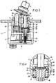
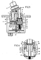
- the positions of the handle shown in figures 3 and 5 allow to control said first pusher 3 respectively to its depressed position, and its extended position.
- said pusher 3 extends between a head 12 and a foot 13.
- the head 12 is mounted to move back and forth at the open end 6 of the body 2 so that the skirt 10 of the handle 4 is in simple support on the head 12.
- the foot 13 of the pusher 3 is housed in the bottom 8 of the cavity 5 to allow the control of at least a first external receiver to the remote control.
- the head 12 of the first pusher 3 comes into abutment under the skirt 10 of the handle 4 and is controlled between its rest position such that represented at Figures 1 and 2 , and its depressed position as shown in Figures 3 and 4 as is well known in the state of the art.
- this first pusher 3 is also movable towards an extended position as shown in FIGS. Figures 5 and 6 , this output position being opposite to the depressed position relative to the rest position.
- the remote control has first elastic return means 15 which are housed in the cavity 5 to urge the first pusher 3 towards its extended position so that the pusher has an upward movement of its own. .
- the handle 4 is tilted so as to disengage the head 12 from the pusher 3 so that the head 12 has an upward movement to follow the skirt 10 under the sole action of the first elastic return means 15.
- the remote control 1 further comprises detection means 17 which detect any position occupied by the first pusher 3 between its output and depressed positions.
- the cavity 5 is stepped and comprises a first shoulder 20 located below the emergent end 6 and which extends substantially transversely to the displacement of the first pusher 3 that is to say, substantially perpendicular to the axis XX.
- the pusher 3 has an intermediate portion 22 which is larger in diameter than the head 12 and the foot 13 of the pusher and which is implanted along the length of said pusher.
- the head 12, the foot 13 and the intermediate portion 22 are integral in motion.
- This intermediate section thus has an upper face 23 which delimits an upper stop and a lower face 24 which delimits a lower stop. The upper face 23 is turned towards the first shoulder 20 while the lower face 24 is turned towards the bottom 8 of the cavity 5.
- the upper abutment 23 is intended to bear against the first shoulder 20 as shown in FIGS. Figures 5 and 6 to define the output position of this pusher 3 while the lower stop 24 is intended to bear against the bottom 8 of this cavity in the depressed position of the pusher as shown in FIGS. Figures 3 and 4 .
- the first return means 15 preferably comprise a collar 26 which is carried by the intermediate section 22, in the vicinity of the upper stop 23, this collar being turned towards the bottom 8 of the cavity 5.
- the first elastic return means 15 also comprise a first compression spring 27 which is interposed between the collar 26 and the bottom 8 of the cavity 5. This compression spring 27 is of a diameter slightly greater than that of the intermediate section 22 so as to be fitted on this section to reach the collar 26.
- the first pusher 3 has an upward movement which is forced by the first compression spring 27 so that when the head 12 of this pusher 3 is disengaged by the skirt 10 of the handle 4, the pusher 3 has an upward movement towards its output position through the compression means 27.
- the remote control 1 has second resilient return means 30 which are housed in the cavity 5 to recall the first pusher 3 from its depressed position as shown in FIGS. Figures 3 and 4 towards its rest position as shown in Figures 1 and 2 .
- the second elastic return means 30 comprise a ring 31 which is concentric with the first pusher 3, a second compression spring 32 which is interposed between the ring 31 and the bottom 8 of the cavity 5, and a peripheral relief 33 which is secured in movement of the first pusher 3 and which is intended to rest on the ring 31.
- the cavity 5 has a second shoulder 35 located at an intermediate level between the first shoulder 20 and the bottom 8 of the cavity 5.
- the second compression spring 32 urges the ring 31 towards the second shoulder 35 so that this ring 31 abuts against this second shoulder when the first pusher 3 is in its rest position as shown in FIGS. Figures 1 and 2 .
- the second shoulder 35 thus defines, as it were, the rest position of the pusher 3.
- the pusher 3 is thus in equilibrium in its rest position between the action exerted by the skirt 10 on the head 12 which tends to drive the pusher 3, and the action of the first compression spring and the second compression spring 27 and 32.
- the ring 31 is in abutment against the second shoulder 35 while the peripheral relief 33 abuts against this ring 31 under the action of the handle 4.
- the skirt 10 of the handle 4 urges the head 12 of the pusher 3 downwards so that the intermediate portion 22 drives the concentric ring 31 in downward movement and compresses the compression springs 27 and 32 until this section intermediate 22 is in low abutment against the bottom 8 of the cavity 5.
- the pusher 12 occupies any position between its depressed position and its extended position.
- the foot 13 of the pusher 3 extends beyond the bottom 8 of the cavity 5 so as to cross the bottom reciprocating between its output and depressed positions.
- the detection means 17 are of the type without mechanical contact and comprise for example a magnet 40 which is integral in movement of the pusher 3 being mounted inside the foot 13 of this pusher, as well as an effect sensor.
- Hall 41 which is mounted in the body 2 of the remote control 1, facing the displacement of the magnet 40 between the depressed and output positions of the first pusher 3. More specifically, the Hall effect sensor 41 is mounted in the body 2, beyond the bottom 8 of the cavity 5.
- this sensor 41 may be embedded in a material such as resin to make it waterproof.
- a second pusher 50 is implanted in the body 2 of the remote control 1 to allow the balance of the handle 4.
- This second pusher 50 is a passive pusher as far as it does not allow to transmit a control signal to a receiver member. It is implanted in a cavity 51 formed in the body 2 opposite the first cavity 5 with respect to the axis of the handle 4.
- This second pusher 50 also has a head 52 bearing under the skirt 10 of the handle 4 and a foot 53.
- This foot 53 abuts in the bottom of the second cavity 51 and has a collar 55 which abuts against the upper portion 56 of the cavity 51.
- This cavity 51 extends parallel to the axis XX and between the levels defined by the bottom 8 of the first cavity 5 and the rest position defined by the second shoulder 35 of the first cavity 5.
- This second pusher 50 is biased by a third compression spring 60 which is interposed between the collar 55 and the bottom of this cavity so as to resiliently urge this second pusher 50 and to cause the operator the same effort on the handle 4 to depress the first pusher 3 or the second pusher 50.
- the first pusher 3 is equipped with means for controlling a receiving member while the second pusher 50 is simply there for the symmetry of the forces to exert on the handle 4.
- the number of component parts is thus reduced so as to minimize the cost price and the risks of technical failure.
- a positive mechanical connection can also be created between the head 12 of the pusher 3 to overcome a possible failure of one of the compression springs or for the case where the pusher 3 remains stuck during its upward movement.
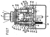
- the remote control 1 for public works machinery comprises, as in the first embodiment, in a manner known per se, a body 2, at least one first pusher 62 which is slidably mounted in the body 2 and a handle 4 which is mounted swinging relative to this body to control the back and forth movements of the first pusher 62 inside the body 2.
- the first pusher 62 is slidably mounted inside a first cavity 63 which extends between a through end 65 on at least one upper face 7 of the body 2 and a bottom 66 opposite this open end 65.
- the cavity 63 comprises a shoulder 64 located below the open end 65 and which extends substantially transversely to the displacement of the first pusher 62, that is to say, substantially perpendicular to the axis XX.
- the bottom of the housing 72 has a central opening 73 of axis XX of diameter substantially equal to the stem of the foot 69 allowing the passage thereof.
- This arrangement ensures that the foot 69 and the head 67 are integral in movement, and can move in translation along the axis XX with respect to the intermediate section 70.
- the head 67 of the first pusher 62 abuts the skirt 10 of the handle 4 and is controlled between its rest position as shown in FIG. figure 7 , and its depressed position as shown in figure 8 as is well known in the state of the art.
- the foot 69 of the pusher 62 is housed in the bottom 66 of the cavity 63 to allow the control of at least a first external receiver on the remote control.
- the head 67 of the first pusher 62 is furthermore movable towards an extended position as represented in FIG. figure 9 , this output position being opposite to the depressed position relative to the rest position.
- the remote control according to the present invention has first elastic return means 74 constituted by a spring 74 housed axially between the bottom of the housing 72 and the bottom 68 of the cap forming the head 67.
- the first elastic return means 74 bias the head 67 of the first pusher 62 towards its extended position so that the head 67 of the pusher 62 has an upward movement of its own. During this upward movement, the handle 4 is tilted so as to disengage the head 67 from the pusher 62 so that the head 67 has an upward movement to follow the skirt 10 under the action of the first elastic return means 74 towards its exit position.
- the intermediate section 70 has an upper face 75 which delimits an upper stop and a lower face 76 which delimits a lower stop.
- the upper face 75 is turned towards the shoulder 64 while the lower face 76 is turned towards the bottom 66 of the cavity 63.
- the upper stop 75 is intended to bear against the shoulder 64 as shown in FIGS. figures 7 and 9 when the pusher is not in the depressed position, while the lower stop 76 is intended to bear against the bottom 66 of this cavity in the 'depressed position of the pusher as shown in FIG. figure 8 .
- the shoulder 64 thus defines, as it were, the rest position of the pusher 3.
- the remote control 1 has second elastic return means 77 which are housed in the cavity 63 to recall the first pusher 62 from its depressed position as shown in FIG. figure 8 towards its rest position as shown in figure 7 .
- the second return means 77 preferably comprise a flange 78 which is carried by the intermediate section 70, in the vicinity of the upper stop 75, this flange being turned towards the bottom 66 of the cavity 63.
- the second resilient return means 77 also comprise a second compression spring 79 which is interposed between the flange 78 and the bottom 66 of the cavity 63. This compression spring 79 is of a diameter slightly greater than that of the intermediate section 70 so as to be fitted on this section to reach the flange 78.
- the remote control 1 comprises detection means 17 which make it possible to detect any position occupied by this first pusher 62 between its output and depressed positions.
- the pusher 62 is in equilibrium in its rest position between the action exerted by the skirt 10 on the head 67 which tends to push the pusher 62, and the action of the first compression spring and the second compression spring 74 and 79.
- the upper stop 75 bears against the shoulder 64 while the head 67 is in axial abutment against the bottom of the housing 72 of the intermediate section 70 under the action of the handle 4.
- the first spring 74 is compressed.
- the skirt 10 of the handle 4 urges the head 67 of the pusher 62 downwards so that the intermediate section 70 compresses the second compression spring 79 until this intermediate portion 70 is in a low abutment against the bottom 66 of the cavity 63.
- the head 67 of the pusher 62 occupies any position between its depressed position and its extended position.
- the foot 69 of the pusher 62 extends beyond the bottom 66 of the cavity 63 so as to cross the bottom reciprocating between its output and depressed positions.
- the detection means 17 are of the type without mechanical contact and comprise for example a magnet 40 which is integral in motion of the foot of the pusher 62 being mounted inside thereof , as well as a Hall effect sensor 41 which is mounted in the body 2 of the remote control 1, facing the displacement of the magnet 40 between the depressed and the first output positions.
- Pusher 62 Specifically, the Hall effect sensor 41 is mounted in the body 2, beyond the bottom 66 of the cavity 63.
- this sensor 41 can be embedded in a material such as resin to make it tight .
- a second pusher 80 is implanted in the body 2 of the remote control 1 to allow the balance of the handle 4.
- This second pusher 80 is a passive pusher in that it does not allow to transmit a control signal to a receiving member. It is implanted in a cavity 82 formed in the body 2 opposite the first cavity 63 with respect to the axis of the handle 4.
- This cavity 82 is symmetrical about the axis of the handle of the first cavity 63. It comprises a shoulder 86 symmetrical with the shoulder 64 of the first cavity. The bottom of this cavity is not pierced like the first cavity 63.
- This second pusher 80 also has a head 83 bearing under the skirt 10 of the handle 4 and a section 84 secured to the head 83.
- the section 84 of the second pusher 80 is identical to the intermediate section 70.
- the first pusher, and the head 83 of the second pusher is identical to the head 67 of the first pusher 62, these two parts being however integral, unlike the first pusher 62.
- This section 84 abuts in the bottom of the second cavity 82 and has a flange 85 which abuts against the shoulder 86 of the cavity 82.
- This cavity 82 extends parallel to the axis XX and between the defined levels. by the bottom 66 of the first cavity 63 and the rest position defined by the shoulder 64 of the first cavity 63.
- this second pusher 80 is biased by a third compression spring 86, identical to the first compression spring 74, which is interposed between the flange 85 and the bottom of this cavity so as to resiliently urge the second pusher 80 and cause for the operator, the same effort on the handle 4 to push the first pusher 62 or the second pusher 80.
- the number of component parts is reduced compared to the first embodiment so as to minimize the cost price and the risk of technical failure.
- the stroke of the first compression spring is decreased compared to the first embodiment.
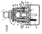
- the second pusher 87 which likewise comprises a head 88 and a section 89.
- the head and the section are not integral, a compression spring 90 being housed between the head 88 and the section 89, similarly to the first pusher.
- the head 88 of the second pusher 87 follows the skirt 10 of the handle 4
- This arrangement makes it possible to reinforce the symmetry of the assembly, thus avoiding assembly errors, and moreover guarantees a torque in the symmetrical handle between the driving and output positions.
Landscapes
- Engineering & Computer Science (AREA)
- Physics & Mathematics (AREA)
- Fluid Mechanics (AREA)
- Mechanical Engineering (AREA)
- General Engineering & Computer Science (AREA)
- Mechanical Control Devices (AREA)
- Percussion Or Vibration Massage (AREA)
- Actuator (AREA)
- Operation Control Of Excavators (AREA)
- Vending Machines For Individual Products (AREA)
- Heat Treatments In General, Especially Conveying And Cooling (AREA)
- Tunnel Furnaces (AREA)
- Servomotors (AREA)
- Fluid-Damping Devices (AREA)
- Catching Or Destruction (AREA)
Claims (19)
- Fernsteuerung (1) fiir Tiefbaumaschinen des Typs, der folgende Bestandteile umfasst:- ein Gehäuse (2), das mindestens einen Hohlraum (5, 63) einschließt, der sich zwischen einem Ende (6, 65), das an mindestens einer Oberseite (7) des Gehäuses (2) mündet, und einem Boden (8, 66) erstreckt, der dem mündenden Ende gegenüber liegt,- mindestens einen ersten Stößel (3, 62), der sich zwischen einem Kopf (12, 67) und einem Fuß (13, 69) erstreckt und der in hin- und hergleitender Bewegung in diesem mindestens einem Hohlraum (5, 63) des Gehäuses (2) montiert ist, und zwar in einer axialen Richtung zwischen einer Ruhestellung und einer abgesenkten Stellung, und der dazu dient, das Steuern mindestens eines ersten Empfängers außerhalb der Fernbedienung zu ermöglichen, und- einen Handgriff (4), der einen transversalen Halsring (10) umfasst und der, bezogen auf das Gehäuse (2), gegenüber der Oberseite (7) dieses Gehäuses (2) kippbar montiert ist, um die Hin- und Herbewegung des ersten Stößels (3, 62) zu steuern, wobei der Halsring (10) in einfacher Auflage auf dem Kopf (12, 67) des Stößels (3, 62) liegt und wobei die Achse (Y-Y) des Handgriffs (4) mit der Achse (X-X) des Stößels (3, 62) einen veränderlichen spitzen Winkel bildet, und wobei sich der Handgriff parallel zur Achse des Stößels (3, 62) erstreckt, wenn sich dieser in Ruhestellung befindet,dadurch gekennzeichnet, dass zumindest der Kopf (12, 67) des ersten Stößels (3, 62) außerdem zu einer ausgefahrenen Stellung beweglich ist, die, bezogen auf die Ruhestellung, der abgesenkten Stellung entgegengesetzt ist,
und dadurch, dass erste elastische Rückholmittel (15, 74) den Kopf (12, 67) des ersten Stößels (3, 62) in Richtung seiner ausgefahrenen Stellung hin vorspannen, so dass mindestens der Kopf (12, 67) des ersten Stößels (3, 62) eine autonome aufsteigende Bewegung macht, um dem Halsring (10) zu folgen, wenn der Handgriff (4) gekippt wird,
und dadurch, dass die Fernsteuerung (1) außerdem Detektionsmittel (17) um fasst, um jede Stellung zu erfassen, die der Kopf des ersten Stößels (3, 62) zwischen seinen ausgefahrenen und seiner abgesenkten Stellung einnimmt. - Fernsteuerung (1) nach Anspruch 1, dadurch gekennzeichnet, dass die Detektionsmittel (17) solche ohne mechanischen Kontakt sind.
- Fernsteuerung (1) nach Anspruch 2, dadurch gekennzeichnet, dass die Detektionsmittel (17) einen Magneten (40) umfassen, der sich fest verbunden mit dem Kopf des Stößels (3, 62) bewegt.
- Fernsteuerung (1) nach einem der Ansprüche 1 bis 3, dadurch gekennzeichnet, dass der Hohlraum (5) gestuft ist und einen ersten Absatz (20) hat, der im wesentlichen quer zur Bewegung des ersten Stößels (3) verläuft, und dadurch, dass dieser Stößel (3) einen Zwischenabschnitt (22) aufweist, der sich fest verbunden mit dem Kopf (12) und dem Fuß (13) des Stößels (3) bewegt und der zwischen dessen Kopf (12) und dessen Fuß (13) liegt, und der einen oberen Anschlag (23) und einen unteren Anschlag (24) abgrenzt, wobei der obere Anschlag (23) in der ausgefahrenen Stellung des Stößels (3) gegen den ersten Absatz (20) zu liegen kommt und der untere Anschlag (24) in der abgesenkten Stellung dieses Stößels (3) gegen den Boden (8) des Hohlraums (5) zu liegen kommt.
- Fernsteuerung (1) nach Anspruch 4, dadurch gekennzeichnet, dass die ersten Rückholmittel (15) im Hohlraum (5) untergebracht sind.
- Fernsteuerung (1) nach einem der Ansprüche 4 und 5, dadurch gekennzeichnet, dass die ersten Rückholmittel (15) einen Kragen (26) umfassen, der auf dem Zwischenabschnitt (22) nahe beim oberen Anschlag (23) sitzt, und eine erste Druckfeder (27), die zwischen dem Kragen (26) und dem Boden (8) des Hohlraums (5) eingesetzt ist.
- Fernsteuerung (1) nach einem der Ansprüche 1 bis 3, dadurch gekennzeichnet, dass der Hohlraum (63) einen Absatz (64) aufweist, der im wesentlichen quer zur Bewegung des ersten Stößels (62) verläuft, und dadurch, dass der Stößel (3) einen Kopf (67) und einen Fuß (69) umfasst, die sich fest verbunden bewegen und die in Translationsbewegung entlang der Achse (X-X) des Stößels (62) beweglich sind, bezogen auf einen Zwischenabschnitt (70), der zwischen dem Kopf (67) und dem Fuß (69) liegt und der einen oberen Anschlag (75) und einen unteren Anschlag (76) abgrenzt, wobei der obere Anschlag (75) gegen den Absatz (64) zu liegen kommt, wenn der Kopf (67) des Stößels (62) sich zwischen seiner Ruhestellung und seiner ausgefahrenen Stellung befindet, und der untere Anschlag (76) in der abgesenkten) Stellung des Stößels (62) gegen den Boden (66) des Hohlraums (63) zu liegen kommt.
- Fernsteuerung (1) nach Anspruch 7, dadurch gekennzeichnet, dass die ersten elastischen Rückholmittel (74) zwischen dem Kopf (67) des Stößels und dem Zwischenabschnitt (70) des Stößels (62) untergebracht sind.
- Fernsteuerung (1) nach einem der Ansprüche 7 und 8, dadurch gekennzeichnet, dass die ersten elastischen Rückholmittel eine erste Druckfeder (74) umfassen, die zwischen dem Kopf (67) des Stößels und dem Zwischenabschnitt (70) des Stößels (62) eingesetzt ist.
- Fernsteuerung (1) nach einem der Ansprüche 1 bis 9, dadurch gekennzeichnet, dass die zweiten elastischen Rückholmittel (30, 77) in dem Hohlraum (5, 63) untergebracht sind, um den ersten Stößel (3, 62) von seiner abgesenkten Stellung in seine Ruhestellung zu holen.
- Fernsteuerung (1) nach Anspruch 10, dadurch gekennzeichnet, dass die zweiten Rückholmittel (30) einen Ring (31) umfassen, der mit dem ersten Stößel (3) konzentrisch ist, eine zweite Druckfeder (32), die zwischen dem Ring (31) und dem Boden (8) des Hohlraums (3) eingesetzt ist, sowie ein peripheres Relief (33), das mit dem ersten Stößel (3) fest verbunden ist und dazu dient, sich auf dem Ring (31) abzustützen, wobei der Hohlraum (5) außerdem einen zweiten Absatz (35) hat, auf dem der Ring (31) in der Ruhestellung des ersten Stößels (3) anliegt.
- Fernsteuerung (1) nach Anspruch 10, dadurch gekennzeichnet, dass die zweiten Rückholmittel (77) einen Kragen (78) umfassen, der am Zwischenabschnitt (70) nahe beim oberen Anschlag (75) sitzt, sowie eine zweite Druckfeder (79), die zwischen dem Kragen (78) und dem Boden (66) des Hohlraums (62) eingesetzt ist.
- Fernsteuerung (1) nach einem der Ansprüche 1 bis 12, dadurch gekennzeichnet, dass ein zweiter Stößel (50, 80, 87) in einem zweiten Hohlraum (51, 82) des Gehäuses (2) montiert ist, wobei der zweite Stößel (50, 80, 87) von einer dritten Druckfeder (60, 86) elastisch so vorgespannt ist, dass die Kraft, die auf den Handgriff (4) ausgeübt werden muss, um einen der ersten (3, 62) und zweiten (50, 80, 87) Stößel hineinzudrücken, im wesentlichen konstant ist.
- Fernsteuerung (1) nach Anspruch 13, dadurch gekennzeichnet, dass der zweite Hohlraum (82) symmetrisch ist zum ersten Hohlraum, bezogen auf die Achse des Handgriffs (4) in Ruhestellung.
- Fernsteuerung nach den Ansprüchen 13 und 14, dadurch gekennzeichnet, dass zumindest der Kopf (88) des zweiten Stößels (87) zu einer ausgefahrenen Stellung hin beweglich ist, die, bezogen auf die Ruhestellung, der abgesenkten Stellung entgegengesetzt ist, und dadurch dass elastische Rückholmittel (90) den Kopf (88) des Stößels (87) in Richtung seiner ausgefahrenen Stellung vorspannen, so dass zumindest der Kopf (88) des zweiten Stößels (87) eine autonome aufsteigende Bewegung macht.
- Fernsteuerung (1) nach einem der Ansprüche 1 bis 15, dadurch gekennzeichnet, dass der Fuß (13, 69) des ersten Stößels (3, 62) den Boden (8, 66) des Hohlraums (5, 63) durchquerend montiert ist und in seinem Innern den Magneten (40) trägt.
- Fernsteuerung (1) nach Anspruch 16, dadurch gekennzeichnet, dass ein Hall-Effekt-Sensor im Gehäuse (2) der Fernbedienung (1) gegenüber der Bewegungsbahn des Magneten (40) zwischen der abgesenkten und der ausgefahrenen Stellung des ersten Stößels (3, 62) montiert ist.
- Fernbedienung (1) nach den Ansprüchen 13 bis 17, dadurch gekennzeichnet, dass der zweite Stößel (50, 80, 87), bezogen auf die Achse des Handgriffs (4), entgegengesetzt zum ersten Stößel (3, 62), eingesetzt ist.
- Fernsteuerung (1) nach den Ansprüchen 17 und 18, dadurch gekennzeichnet, dass der Hall-Effekt-Sensor (41) in Kunstharz eingegossen ist, um sich in einem wasserdichten Bereich zu befinden.
Applications Claiming Priority (3)
| Application Number | Priority Date | Filing Date | Title |
|---|---|---|---|
| FR0308566A FR2857488A1 (fr) | 2003-07-11 | 2003-07-11 | Telecommande pour engins de travaux publics a poussoir suiveur |
| FR0401894A FR2857489B1 (fr) | 2003-07-11 | 2004-02-25 | Telecommande pour engins de travaux publics a poussoir suiveur |
| PCT/FR2004/001601 WO2005015031A1 (fr) | 2003-07-11 | 2004-06-24 | Telecommande pour engins de travaux publics a poussoir suiveur |
Publications (2)
| Publication Number | Publication Date |
|---|---|
| EP1644645A1 EP1644645A1 (de) | 2006-04-12 |
| EP1644645B1 true EP1644645B1 (de) | 2008-02-20 |
Family
ID=33542633
Family Applications (1)
| Application Number | Title | Priority Date | Filing Date |
|---|---|---|---|
| EP04767450A Expired - Lifetime EP1644645B1 (de) | 2003-07-11 | 2004-06-24 | Fernsteuerung für schwere baumaschinen mit kolbenstangenstössel |
Country Status (9)
| Country | Link |
|---|---|
| US (1) | US7467644B2 (de) |
| EP (1) | EP1644645B1 (de) |
| JP (1) | JP2007526970A (de) |
| KR (1) | KR101115555B1 (de) |
| AT (1) | ATE386886T1 (de) |
| DE (1) | DE602004011940T2 (de) |
| DK (1) | DK1644645T3 (de) |
| FR (1) | FR2857489B1 (de) |
| WO (1) | WO2005015031A1 (de) |
Cited By (4)
| Publication number | Priority date | Publication date | Assignee | Title |
|---|---|---|---|---|
| IT202100000875A1 (it) | 2021-01-19 | 2022-07-19 | Walvoil Spa | Dispositivo di comando a leva |
| DE102021205349A1 (de) | 2021-05-26 | 2022-12-01 | Robert Bosch Gesellschaft mit beschränkter Haftung | Joystick |
| DE102021205814A1 (de) | 2021-06-09 | 2022-12-15 | Robert Bosch Gesellschaft mit beschränkter Haftung | Joystick |
| DE102022200968A1 (de) | 2022-01-31 | 2023-08-03 | Robert Bosch Gesellschaft mit beschränkter Haftung | Joystick |
Families Citing this family (14)
| Publication number | Priority date | Publication date | Assignee | Title |
|---|---|---|---|---|
| FR2886035B1 (fr) * | 2005-05-18 | 2007-08-03 | Bosch Rexroth D S I Soc Par Ac | Telecommande d'engin, en particulier d'engin de travaux publics |
| JP4716499B2 (ja) * | 2005-10-17 | 2011-07-06 | 株式会社小松製作所 | レバー位置検出機能付パイロットバルブ |
| KR101138485B1 (ko) | 2006-09-28 | 2012-07-02 | 콸콤 인코포레이티드 | 효율성을 위한 통신 신호들의 번들링 |
| FR2938309B1 (fr) * | 2008-11-12 | 2010-10-29 | Bosch Rexroth Dsi Sas | Dispositif de regulation de pression, notamment du type telecommande hydraulique |
| JP5238739B2 (ja) * | 2010-02-26 | 2013-07-17 | 川崎重工業株式会社 | 操作装置 |
| FR2970350B1 (fr) * | 2011-01-07 | 2013-11-01 | Bosch Rexroth Dsi Sas | Dispositif de regulation de pression avec detection de la position neutre |
| US20150345991A1 (en) * | 2013-10-18 | 2015-12-03 | Komatsu Ltd. | Stroke detection device, stroke detection method, stroke detection system, operation lever unit, and operation lever stroke detection system |
| US11079294B2 (en) * | 2017-02-28 | 2021-08-03 | Komatsu Ltd. | Operation lever |
| US12117862B2 (en) | 2019-04-11 | 2024-10-15 | Walvoil S.P.A | Modular control apparatus for actuating hydraulic valve systems |
| CN109976382B (zh) * | 2019-04-19 | 2024-11-05 | 厦门扬恩科技有限公司 | 新型3d遥控器 |
| FR3096162B1 (fr) | 2019-05-15 | 2021-06-11 | Bosch Gmbh Robert | « Télécommande à manette d’engin de travaux » |
| IT202000023860A1 (it) | 2020-10-09 | 2022-04-09 | Walvoil Spa | Apparecchiatura di comando per l’azionamento di sistemi idraulici valvolari |
| EP3992749A1 (de) | 2020-10-08 | 2022-05-04 | Walvoil S.p.A. | Bedienelement zum steuern von hydraulischen ventilsystemen |
| IT202000023773A1 (it) | 2020-10-08 | 2022-04-08 | Walvoil Spa | Apparecchiatura di comando per l’azionamento di sistemi idraulici valvolari |
Family Cites Families (11)
| Publication number | Priority date | Publication date | Assignee | Title |
|---|---|---|---|---|
| DE2359748A1 (de) * | 1973-11-30 | 1975-06-05 | Lamborghini Oleodinamica | Vorrichtung zur verbesserung von fernbedienten pressoel-servostufenantrieben |
| FR2540959B1 (fr) * | 1983-02-15 | 1986-05-16 | Rexroth Sigma | Dispositif distributeur de fluide, notamment pour telecommande |
| US5010263A (en) * | 1989-02-21 | 1991-04-23 | Mitsubishi Denki Kabushiki Kaisha | Hall effect type sensing device |
| FR2648582B1 (fr) * | 1989-06-16 | 1996-08-09 | Rexroth Sigma | Dispositif de telecommande electrique du type manipulateur ou analogue |
| US5313844A (en) * | 1992-06-10 | 1994-05-24 | Micro Hydraulics Inc. | Flow transducer |
| US5320123A (en) * | 1993-05-24 | 1994-06-14 | Honeywell Inc. | Valve with dynamic function checking capability |
| WO1996015374A1 (en) * | 1994-11-14 | 1996-05-23 | Komatsu Ltd. | Hydraulic pilot valve |
| FR2781845B1 (fr) * | 1998-07-28 | 2002-03-08 | Mannesmann Rexroth Sa | Dispositif distributeur de fluide notamment pour telecommande hydraulique |
| FR2801350B1 (fr) * | 1999-11-23 | 2002-03-29 | Mannesmann Rexroth Sa | Dispositif distributeur de fluide, notamment pour telecommande hydraulique |
| JP2003036121A (ja) * | 2001-07-24 | 2003-02-07 | Hitachi Constr Mach Co Ltd | 電気式操作レバー装置 |
| JP4099749B2 (ja) * | 2002-01-17 | 2008-06-11 | Smc株式会社 | エアサーボバルブ |
-
2004
- 2004-02-25 FR FR0401894A patent/FR2857489B1/fr not_active Expired - Fee Related
- 2004-06-24 KR KR1020067000735A patent/KR101115555B1/ko not_active Expired - Fee Related
- 2004-06-24 US US10/559,930 patent/US7467644B2/en not_active Expired - Fee Related
- 2004-06-24 JP JP2006519948A patent/JP2007526970A/ja active Pending
- 2004-06-24 DE DE200460011940 patent/DE602004011940T2/de not_active Expired - Lifetime
- 2004-06-24 WO PCT/FR2004/001601 patent/WO2005015031A1/fr not_active Ceased
- 2004-06-24 AT AT04767450T patent/ATE386886T1/de not_active IP Right Cessation
- 2004-06-24 DK DK04767450T patent/DK1644645T3/da active
- 2004-06-24 EP EP04767450A patent/EP1644645B1/de not_active Expired - Lifetime
Cited By (4)
| Publication number | Priority date | Publication date | Assignee | Title |
|---|---|---|---|---|
| IT202100000875A1 (it) | 2021-01-19 | 2022-07-19 | Walvoil Spa | Dispositivo di comando a leva |
| DE102021205349A1 (de) | 2021-05-26 | 2022-12-01 | Robert Bosch Gesellschaft mit beschränkter Haftung | Joystick |
| DE102021205814A1 (de) | 2021-06-09 | 2022-12-15 | Robert Bosch Gesellschaft mit beschränkter Haftung | Joystick |
| DE102022200968A1 (de) | 2022-01-31 | 2023-08-03 | Robert Bosch Gesellschaft mit beschränkter Haftung | Joystick |
Also Published As
| Publication number | Publication date |
|---|---|
| KR101115555B1 (ko) | 2012-03-05 |
| US20060169498A1 (en) | 2006-08-03 |
| WO2005015031A1 (fr) | 2005-02-17 |
| KR20060035749A (ko) | 2006-04-26 |
| ATE386886T1 (de) | 2008-03-15 |
| FR2857489B1 (fr) | 2006-06-09 |
| DE602004011940D1 (de) | 2008-04-03 |
| JP2007526970A (ja) | 2007-09-20 |
| US7467644B2 (en) | 2008-12-23 |
| DK1644645T3 (da) | 2008-06-23 |
| EP1644645A1 (de) | 2006-04-12 |
| DE602004011940T2 (de) | 2009-02-26 |
| FR2857489A1 (fr) | 2005-01-14 |
Similar Documents
| Publication | Publication Date | Title |
|---|---|---|
| FR2857489A1 (fr) | Telecommande pour engins de travaux publics a poussoir suiveur | |
| EP2659149B1 (de) | Vorrichtung zum gegenseitigen verriegeln zweier gleitbare montierbarer rohre | |
| EP3451071A1 (de) | Vorrichtung mit drucktaste für uhr | |
| EP0117806A1 (de) | Flüssigkeitsverteiler, insbesondere für Fernsteuerung | |
| FR2638791A1 (fr) | Verrou pour support d'equipement | |
| EP1538050B1 (de) | Bremskraftverstärker mit einem in der Stösselstange integrierten Dekompressionskolben aus einem elastischen Material | |
| FR2982329A1 (fr) | Machine a pistons axiaux | |
| EP3749454A1 (de) | System zum auswurf von spitzen von probenahmepipetten mit verbesserter ergonomie | |
| FR2786423A1 (fr) | Outil emporte-piece hydraulique | |
| FR2724239A1 (fr) | Dispositif de poussoir etanche, notamment pour commander une piece d'horlogerie | |
| EP1906034A2 (de) | Gelenkverbindung zwischen einem Hebel und einer Betätigungsstange | |
| EP2141554A2 (de) | Drücker | |
| FR2857488A1 (fr) | Telecommande pour engins de travaux publics a poussoir suiveur | |
| EP3742235A1 (de) | Druckknopfsystem und dieses umfassende uhr | |
| CH710271A2 (fr) | Organe de commande télescopique. | |
| EP4092490B1 (de) | Steuervorrichtung für ein uhrwerk mit taktiler rückmeldung und uhrwerk, insbesondere armbanduhr, mit einer solchen vorrichtung | |
| EP0154584B1 (de) | Selbsttätige Nachstellvorrichtung für eine Kupplung | |
| EP1056633B1 (de) | Servomotor mit filter kontrollierter dichtheit | |
| FR2739827A1 (fr) | Dispositif de commande pour un frein de bicyclette, comprenant un dispositif destine a limiter la force de freinage | |
| FR2801350A1 (fr) | Dispositif distributeur de fluide, notamment pour telecommande hydraulique | |
| WO2014206830A2 (fr) | Servofrein électromécanique | |
| FR2660679A1 (fr) | Dispositif de commande a bouton-poussoir et came basculante pour mecanisme de chasse d'eau. | |
| EP0236234B1 (de) | Federnde, blockierbare Vorrichtung, die einen Arm variabler Länge bildet | |
| CH716210A2 (fr) | Système de bouton-poussoir, et pièce d'horlogerie le comprenant. | |
| FR2818222A1 (fr) | Dispositif de freinage assiste a valve d'urgence avec saut eleve, et servomoteur pour un tel dispositif |
Legal Events
| Date | Code | Title | Description |
|---|---|---|---|
| PUAI | Public reference made under article 153(3) epc to a published international application that has entered the european phase |
Free format text: ORIGINAL CODE: 0009012 |
|
| 17P | Request for examination filed |
Effective date: 20051129 |
|
| AK | Designated contracting states |
Kind code of ref document: A1 Designated state(s): AT BE BG CH CY CZ DE DK EE ES FI FR GB GR HU IE IT LI LU MC NL PL PT RO SE SI SK TR |
|
| 17Q | First examination report despatched |
Effective date: 20060821 |
|
| DAX | Request for extension of the european patent (deleted) | ||
| GRAP | Despatch of communication of intention to grant a patent |
Free format text: ORIGINAL CODE: EPIDOSNIGR1 |
|
| GRAS | Grant fee paid |
Free format text: ORIGINAL CODE: EPIDOSNIGR3 |
|
| GRAA | (expected) grant |
Free format text: ORIGINAL CODE: 0009210 |
|
| AK | Designated contracting states |
Kind code of ref document: B1 Designated state(s): AT BE BG CH CY CZ DE DK EE ES FI FR GB GR HU IE IT LI LU MC NL PL PT RO SE SI SK TR |
|
| REG | Reference to a national code |
Ref country code: GB Ref legal event code: FG4D Free format text: NOT ENGLISH |
|
| REG | Reference to a national code |
Ref country code: CH Ref legal event code: EP |
|
| REG | Reference to a national code |
Ref country code: IE Ref legal event code: FG4D Free format text: LANGUAGE OF EP DOCUMENT: FRENCH |
|
| REF | Corresponds to: |
Ref document number: 602004011940 Country of ref document: DE Date of ref document: 20080403 Kind code of ref document: P |
|
| GBT | Gb: translation of ep patent filed (gb section 77(6)(a)/1977) |
Effective date: 20080429 |
|
| REG | Reference to a national code |
Ref country code: DK Ref legal event code: T3 |
|
| PG25 | Lapsed in a contracting state [announced via postgrant information from national office to epo] |
Ref country code: ES Free format text: LAPSE BECAUSE OF FAILURE TO SUBMIT A TRANSLATION OF THE DESCRIPTION OR TO PAY THE FEE WITHIN THE PRESCRIBED TIME-LIMIT Effective date: 20080531 Ref country code: FI Free format text: LAPSE BECAUSE OF FAILURE TO SUBMIT A TRANSLATION OF THE DESCRIPTION OR TO PAY THE FEE WITHIN THE PRESCRIBED TIME-LIMIT Effective date: 20080220 |
|
| NLV1 | Nl: lapsed or annulled due to failure to fulfill the requirements of art. 29p and 29m of the patents act | ||
| PG25 | Lapsed in a contracting state [announced via postgrant information from national office to epo] |
Ref country code: AT Free format text: LAPSE BECAUSE OF FAILURE TO SUBMIT A TRANSLATION OF THE DESCRIPTION OR TO PAY THE FEE WITHIN THE PRESCRIBED TIME-LIMIT Effective date: 20080220 |
|
| PG25 | Lapsed in a contracting state [announced via postgrant information from national office to epo] |
Ref country code: SI Free format text: LAPSE BECAUSE OF FAILURE TO SUBMIT A TRANSLATION OF THE DESCRIPTION OR TO PAY THE FEE WITHIN THE PRESCRIBED TIME-LIMIT Effective date: 20080220 Ref country code: PL Free format text: LAPSE BECAUSE OF FAILURE TO SUBMIT A TRANSLATION OF THE DESCRIPTION OR TO PAY THE FEE WITHIN THE PRESCRIBED TIME-LIMIT Effective date: 20080220 |
|
| REG | Reference to a national code |
Ref country code: IE Ref legal event code: FD4D |
|
| PG25 | Lapsed in a contracting state [announced via postgrant information from national office to epo] |
Ref country code: SK Free format text: LAPSE BECAUSE OF FAILURE TO SUBMIT A TRANSLATION OF THE DESCRIPTION OR TO PAY THE FEE WITHIN THE PRESCRIBED TIME-LIMIT Effective date: 20080220 Ref country code: SE Free format text: LAPSE BECAUSE OF FAILURE TO SUBMIT A TRANSLATION OF THE DESCRIPTION OR TO PAY THE FEE WITHIN THE PRESCRIBED TIME-LIMIT Effective date: 20080520 Ref country code: PT Free format text: LAPSE BECAUSE OF FAILURE TO SUBMIT A TRANSLATION OF THE DESCRIPTION OR TO PAY THE FEE WITHIN THE PRESCRIBED TIME-LIMIT Effective date: 20080721 Ref country code: NL Free format text: LAPSE BECAUSE OF FAILURE TO SUBMIT A TRANSLATION OF THE DESCRIPTION OR TO PAY THE FEE WITHIN THE PRESCRIBED TIME-LIMIT Effective date: 20080220 Ref country code: IE Free format text: LAPSE BECAUSE OF FAILURE TO SUBMIT A TRANSLATION OF THE DESCRIPTION OR TO PAY THE FEE WITHIN THE PRESCRIBED TIME-LIMIT Effective date: 20080220 Ref country code: CZ Free format text: LAPSE BECAUSE OF FAILURE TO SUBMIT A TRANSLATION OF THE DESCRIPTION OR TO PAY THE FEE WITHIN THE PRESCRIBED TIME-LIMIT Effective date: 20080220 |
|
| PG25 | Lapsed in a contracting state [announced via postgrant information from national office to epo] |
Ref country code: RO Free format text: LAPSE BECAUSE OF FAILURE TO SUBMIT A TRANSLATION OF THE DESCRIPTION OR TO PAY THE FEE WITHIN THE PRESCRIBED TIME-LIMIT Effective date: 20080220 |
|
| PLBE | No opposition filed within time limit |
Free format text: ORIGINAL CODE: 0009261 |
|
| STAA | Information on the status of an ep patent application or granted ep patent |
Free format text: STATUS: NO OPPOSITION FILED WITHIN TIME LIMIT |
|
| BERE | Be: lapsed |
Owner name: BOSCH REXROTH D.S.I. Effective date: 20080630 |
|
| 26N | No opposition filed |
Effective date: 20081121 |
|
| PG25 | Lapsed in a contracting state [announced via postgrant information from national office to epo] |
Ref country code: MC Free format text: LAPSE BECAUSE OF NON-PAYMENT OF DUE FEES Effective date: 20080630 |
|
| REG | Reference to a national code |
Ref country code: CH Ref legal event code: PL |
|
| PG25 | Lapsed in a contracting state [announced via postgrant information from national office to epo] |
Ref country code: BE Free format text: LAPSE BECAUSE OF NON-PAYMENT OF DUE FEES Effective date: 20080630 |
|
| PG25 | Lapsed in a contracting state [announced via postgrant information from national office to epo] |
Ref country code: EE Free format text: LAPSE BECAUSE OF FAILURE TO SUBMIT A TRANSLATION OF THE DESCRIPTION OR TO PAY THE FEE WITHIN THE PRESCRIBED TIME-LIMIT Effective date: 20080220 Ref country code: BG Free format text: LAPSE BECAUSE OF FAILURE TO SUBMIT A TRANSLATION OF THE DESCRIPTION OR TO PAY THE FEE WITHIN THE PRESCRIBED TIME-LIMIT Effective date: 20080520 |
|
| PG25 | Lapsed in a contracting state [announced via postgrant information from national office to epo] |
Ref country code: CH Free format text: LAPSE BECAUSE OF NON-PAYMENT OF DUE FEES Effective date: 20080630 Ref country code: LI Free format text: LAPSE BECAUSE OF NON-PAYMENT OF DUE FEES Effective date: 20080630 |
|
| PG25 | Lapsed in a contracting state [announced via postgrant information from national office to epo] |
Ref country code: CY Free format text: LAPSE BECAUSE OF FAILURE TO SUBMIT A TRANSLATION OF THE DESCRIPTION OR TO PAY THE FEE WITHIN THE PRESCRIBED TIME-LIMIT Effective date: 20080220 |
|
| PG25 | Lapsed in a contracting state [announced via postgrant information from national office to epo] |
Ref country code: HU Free format text: LAPSE BECAUSE OF FAILURE TO SUBMIT A TRANSLATION OF THE DESCRIPTION OR TO PAY THE FEE WITHIN THE PRESCRIBED TIME-LIMIT Effective date: 20080821 Ref country code: LU Free format text: LAPSE BECAUSE OF NON-PAYMENT OF DUE FEES Effective date: 20080624 |
|
| PG25 | Lapsed in a contracting state [announced via postgrant information from national office to epo] |
Ref country code: TR Free format text: LAPSE BECAUSE OF FAILURE TO SUBMIT A TRANSLATION OF THE DESCRIPTION OR TO PAY THE FEE WITHIN THE PRESCRIBED TIME-LIMIT Effective date: 20080220 |
|
| PG25 | Lapsed in a contracting state [announced via postgrant information from national office to epo] |
Ref country code: GR Free format text: LAPSE BECAUSE OF FAILURE TO SUBMIT A TRANSLATION OF THE DESCRIPTION OR TO PAY THE FEE WITHIN THE PRESCRIBED TIME-LIMIT Effective date: 20080521 |
|
| PGFP | Annual fee paid to national office [announced via postgrant information from national office to epo] |
Ref country code: DK Payment date: 20110517 Year of fee payment: 8 |
|
| REG | Reference to a national code |
Ref country code: DK Ref legal event code: EBP |
|
| PG25 | Lapsed in a contracting state [announced via postgrant information from national office to epo] |
Ref country code: DK Free format text: LAPSE BECAUSE OF NON-PAYMENT OF DUE FEES Effective date: 20120702 |
|
| REG | Reference to a national code |
Ref country code: FR Ref legal event code: PLFP Year of fee payment: 13 |
|
| PGFP | Annual fee paid to national office [announced via postgrant information from national office to epo] |
Ref country code: DE Payment date: 20160428 Year of fee payment: 13 |
|
| PGFP | Annual fee paid to national office [announced via postgrant information from national office to epo] |
Ref country code: IT Payment date: 20160616 Year of fee payment: 13 |
|
| REG | Reference to a national code |
Ref country code: FR Ref legal event code: PLFP Year of fee payment: 14 |
|
| REG | Reference to a national code |
Ref country code: DE Ref legal event code: R119 Ref document number: 602004011940 Country of ref document: DE |
|
| REG | Reference to a national code |
Ref country code: FR Ref legal event code: PLFP Year of fee payment: 15 |
|
| PG25 | Lapsed in a contracting state [announced via postgrant information from national office to epo] |
Ref country code: DE Free format text: LAPSE BECAUSE OF NON-PAYMENT OF DUE FEES Effective date: 20180103 |
|
| PG25 | Lapsed in a contracting state [announced via postgrant information from national office to epo] |
Ref country code: IT Free format text: LAPSE BECAUSE OF NON-PAYMENT OF DUE FEES Effective date: 20170624 |
|
| PGFP | Annual fee paid to national office [announced via postgrant information from national office to epo] |
Ref country code: FR Payment date: 20180420 Year of fee payment: 15 |
|
| PGFP | Annual fee paid to national office [announced via postgrant information from national office to epo] |
Ref country code: GB Payment date: 20190418 Year of fee payment: 16 |
|
| PG25 | Lapsed in a contracting state [announced via postgrant information from national office to epo] |
Ref country code: FR Free format text: LAPSE BECAUSE OF NON-PAYMENT OF DUE FEES Effective date: 20190630 |
|
| GBPC | Gb: european patent ceased through non-payment of renewal fee |
Effective date: 20200624 |
|
| PG25 | Lapsed in a contracting state [announced via postgrant information from national office to epo] |
Ref country code: GB Free format text: LAPSE BECAUSE OF NON-PAYMENT OF DUE FEES Effective date: 20200624 |