EP1643092A1 - Véhicule entraîné par un moteur diesel comprenant un système d'épuration de gaz d'échappement à régénération discontinue par l'injection des vapeurs de carburant - Google Patents
Véhicule entraîné par un moteur diesel comprenant un système d'épuration de gaz d'échappement à régénération discontinue par l'injection des vapeurs de carburant Download PDFInfo
- Publication number
- EP1643092A1 EP1643092A1 EP05028734A EP05028734A EP1643092A1 EP 1643092 A1 EP1643092 A1 EP 1643092A1 EP 05028734 A EP05028734 A EP 05028734A EP 05028734 A EP05028734 A EP 05028734A EP 1643092 A1 EP1643092 A1 EP 1643092A1
- Authority
- EP
- European Patent Office
- Prior art keywords
- fuel
- motor vehicle
- vehicle according
- exhaust gas
- unit
- Prior art date
- Legal status (The legal status is an assumption and is not a legal conclusion. Google has not performed a legal analysis and makes no representation as to the accuracy of the status listed.)
- Granted
Links
Images
Classifications
-
- F—MECHANICAL ENGINEERING; LIGHTING; HEATING; WEAPONS; BLASTING
- F01—MACHINES OR ENGINES IN GENERAL; ENGINE PLANTS IN GENERAL; STEAM ENGINES
- F01N—GAS-FLOW SILENCERS OR EXHAUST APPARATUS FOR MACHINES OR ENGINES IN GENERAL; GAS-FLOW SILENCERS OR EXHAUST APPARATUS FOR INTERNAL COMBUSTION ENGINES
- F01N9/00—Electrical control of exhaust gas treating apparatus
- F01N9/002—Electrical control of exhaust gas treating apparatus of filter regeneration, e.g. detection of clogging
-
- F—MECHANICAL ENGINEERING; LIGHTING; HEATING; WEAPONS; BLASTING
- F01—MACHINES OR ENGINES IN GENERAL; ENGINE PLANTS IN GENERAL; STEAM ENGINES
- F01N—GAS-FLOW SILENCERS OR EXHAUST APPARATUS FOR MACHINES OR ENGINES IN GENERAL; GAS-FLOW SILENCERS OR EXHAUST APPARATUS FOR INTERNAL COMBUSTION ENGINES
- F01N13/00—Exhaust or silencing apparatus characterised by constructional features ; Exhaust or silencing apparatus, or parts thereof, having pertinent characteristics not provided for in, or of interest apart from, groups F01N1/00 - F01N5/00, F01N9/00, F01N11/00
- F01N13/009—Exhaust or silencing apparatus characterised by constructional features ; Exhaust or silencing apparatus, or parts thereof, having pertinent characteristics not provided for in, or of interest apart from, groups F01N1/00 - F01N5/00, F01N9/00, F01N11/00 having two or more separate purifying devices arranged in series
- F01N13/0097—Exhaust or silencing apparatus characterised by constructional features ; Exhaust or silencing apparatus, or parts thereof, having pertinent characteristics not provided for in, or of interest apart from, groups F01N1/00 - F01N5/00, F01N9/00, F01N11/00 having two or more separate purifying devices arranged in series the purifying devices are arranged in a single housing
-
- F—MECHANICAL ENGINEERING; LIGHTING; HEATING; WEAPONS; BLASTING
- F01—MACHINES OR ENGINES IN GENERAL; ENGINE PLANTS IN GENERAL; STEAM ENGINES
- F01N—GAS-FLOW SILENCERS OR EXHAUST APPARATUS FOR MACHINES OR ENGINES IN GENERAL; GAS-FLOW SILENCERS OR EXHAUST APPARATUS FOR INTERNAL COMBUSTION ENGINES
- F01N3/00—Exhaust or silencing apparatus having means for purifying, rendering innocuous, or otherwise treating exhaust
- F01N3/02—Exhaust or silencing apparatus having means for purifying, rendering innocuous, or otherwise treating exhaust for cooling, or for removing solid constituents of, exhaust
- F01N3/021—Exhaust or silencing apparatus having means for purifying, rendering innocuous, or otherwise treating exhaust for cooling, or for removing solid constituents of, exhaust by means of filters
- F01N3/023—Exhaust or silencing apparatus having means for purifying, rendering innocuous, or otherwise treating exhaust for cooling, or for removing solid constituents of, exhaust by means of filters using means for regenerating the filters, e.g. by burning trapped particles
- F01N3/025—Exhaust or silencing apparatus having means for purifying, rendering innocuous, or otherwise treating exhaust for cooling, or for removing solid constituents of, exhaust by means of filters using means for regenerating the filters, e.g. by burning trapped particles using fuel burner or by adding fuel to exhaust
- F01N3/0253—Exhaust or silencing apparatus having means for purifying, rendering innocuous, or otherwise treating exhaust for cooling, or for removing solid constituents of, exhaust by means of filters using means for regenerating the filters, e.g. by burning trapped particles using fuel burner or by adding fuel to exhaust adding fuel to exhaust gases
-
- F—MECHANICAL ENGINEERING; LIGHTING; HEATING; WEAPONS; BLASTING
- F01—MACHINES OR ENGINES IN GENERAL; ENGINE PLANTS IN GENERAL; STEAM ENGINES
- F01N—GAS-FLOW SILENCERS OR EXHAUST APPARATUS FOR MACHINES OR ENGINES IN GENERAL; GAS-FLOW SILENCERS OR EXHAUST APPARATUS FOR INTERNAL COMBUSTION ENGINES
- F01N3/00—Exhaust or silencing apparatus having means for purifying, rendering innocuous, or otherwise treating exhaust
- F01N3/02—Exhaust or silencing apparatus having means for purifying, rendering innocuous, or otherwise treating exhaust for cooling, or for removing solid constituents of, exhaust
- F01N3/021—Exhaust or silencing apparatus having means for purifying, rendering innocuous, or otherwise treating exhaust for cooling, or for removing solid constituents of, exhaust by means of filters
- F01N3/033—Exhaust or silencing apparatus having means for purifying, rendering innocuous, or otherwise treating exhaust for cooling, or for removing solid constituents of, exhaust by means of filters in combination with other devices
- F01N3/035—Exhaust or silencing apparatus having means for purifying, rendering innocuous, or otherwise treating exhaust for cooling, or for removing solid constituents of, exhaust by means of filters in combination with other devices with catalytic reactors, e.g. catalysed diesel particulate filters
-
- F—MECHANICAL ENGINEERING; LIGHTING; HEATING; WEAPONS; BLASTING
- F01—MACHINES OR ENGINES IN GENERAL; ENGINE PLANTS IN GENERAL; STEAM ENGINES
- F01N—GAS-FLOW SILENCERS OR EXHAUST APPARATUS FOR MACHINES OR ENGINES IN GENERAL; GAS-FLOW SILENCERS OR EXHAUST APPARATUS FOR INTERNAL COMBUSTION ENGINES
- F01N3/00—Exhaust or silencing apparatus having means for purifying, rendering innocuous, or otherwise treating exhaust
- F01N3/08—Exhaust or silencing apparatus having means for purifying, rendering innocuous, or otherwise treating exhaust for rendering innocuous
- F01N3/0807—Exhaust or silencing apparatus having means for purifying, rendering innocuous, or otherwise treating exhaust for rendering innocuous by using absorbents or adsorbents
- F01N3/0814—Exhaust or silencing apparatus having means for purifying, rendering innocuous, or otherwise treating exhaust for rendering innocuous by using absorbents or adsorbents combined with catalytic converters, e.g. NOx absorption/storage reduction catalysts
-
- F—MECHANICAL ENGINEERING; LIGHTING; HEATING; WEAPONS; BLASTING
- F01—MACHINES OR ENGINES IN GENERAL; ENGINE PLANTS IN GENERAL; STEAM ENGINES
- F01N—GAS-FLOW SILENCERS OR EXHAUST APPARATUS FOR MACHINES OR ENGINES IN GENERAL; GAS-FLOW SILENCERS OR EXHAUST APPARATUS FOR INTERNAL COMBUSTION ENGINES
- F01N3/00—Exhaust or silencing apparatus having means for purifying, rendering innocuous, or otherwise treating exhaust
- F01N3/08—Exhaust or silencing apparatus having means for purifying, rendering innocuous, or otherwise treating exhaust for rendering innocuous
- F01N3/0807—Exhaust or silencing apparatus having means for purifying, rendering innocuous, or otherwise treating exhaust for rendering innocuous by using absorbents or adsorbents
- F01N3/0828—Exhaust or silencing apparatus having means for purifying, rendering innocuous, or otherwise treating exhaust for rendering innocuous by using absorbents or adsorbents characterised by the absorbed or adsorbed substances
- F01N3/0842—Nitrogen oxides
-
- F—MECHANICAL ENGINEERING; LIGHTING; HEATING; WEAPONS; BLASTING
- F01—MACHINES OR ENGINES IN GENERAL; ENGINE PLANTS IN GENERAL; STEAM ENGINES
- F01N—GAS-FLOW SILENCERS OR EXHAUST APPARATUS FOR MACHINES OR ENGINES IN GENERAL; GAS-FLOW SILENCERS OR EXHAUST APPARATUS FOR INTERNAL COMBUSTION ENGINES
- F01N3/00—Exhaust or silencing apparatus having means for purifying, rendering innocuous, or otherwise treating exhaust
- F01N3/08—Exhaust or silencing apparatus having means for purifying, rendering innocuous, or otherwise treating exhaust for rendering innocuous
- F01N3/0807—Exhaust or silencing apparatus having means for purifying, rendering innocuous, or otherwise treating exhaust for rendering innocuous by using absorbents or adsorbents
- F01N3/0871—Regulation of absorbents or adsorbents, e.g. purging
-
- F—MECHANICAL ENGINEERING; LIGHTING; HEATING; WEAPONS; BLASTING
- F01—MACHINES OR ENGINES IN GENERAL; ENGINE PLANTS IN GENERAL; STEAM ENGINES
- F01N—GAS-FLOW SILENCERS OR EXHAUST APPARATUS FOR MACHINES OR ENGINES IN GENERAL; GAS-FLOW SILENCERS OR EXHAUST APPARATUS FOR INTERNAL COMBUSTION ENGINES
- F01N3/00—Exhaust or silencing apparatus having means for purifying, rendering innocuous, or otherwise treating exhaust
- F01N3/08—Exhaust or silencing apparatus having means for purifying, rendering innocuous, or otherwise treating exhaust for rendering innocuous
- F01N3/10—Exhaust or silencing apparatus having means for purifying, rendering innocuous, or otherwise treating exhaust for rendering innocuous by thermal or catalytic conversion of noxious components of exhaust
- F01N3/105—General auxiliary catalysts, e.g. upstream or downstream of the main catalyst
- F01N3/106—Auxiliary oxidation catalysts
-
- F—MECHANICAL ENGINEERING; LIGHTING; HEATING; WEAPONS; BLASTING
- F01—MACHINES OR ENGINES IN GENERAL; ENGINE PLANTS IN GENERAL; STEAM ENGINES
- F01N—GAS-FLOW SILENCERS OR EXHAUST APPARATUS FOR MACHINES OR ENGINES IN GENERAL; GAS-FLOW SILENCERS OR EXHAUST APPARATUS FOR INTERNAL COMBUSTION ENGINES
- F01N2240/00—Combination or association of two or more different exhaust treating devices, or of at least one such device with an auxiliary device, not covered by indexing codes F01N2230/00 or F01N2250/00, one of the devices being
- F01N2240/16—Combination or association of two or more different exhaust treating devices, or of at least one such device with an auxiliary device, not covered by indexing codes F01N2230/00 or F01N2250/00, one of the devices being an electric heater, i.e. a resistance heater
-
- F—MECHANICAL ENGINEERING; LIGHTING; HEATING; WEAPONS; BLASTING
- F01—MACHINES OR ENGINES IN GENERAL; ENGINE PLANTS IN GENERAL; STEAM ENGINES
- F01N—GAS-FLOW SILENCERS OR EXHAUST APPARATUS FOR MACHINES OR ENGINES IN GENERAL; GAS-FLOW SILENCERS OR EXHAUST APPARATUS FOR INTERNAL COMBUSTION ENGINES
- F01N2470/00—Structure or shape of gas passages, pipes or tubes
- F01N2470/30—Tubes with restrictions, i.e. venturi or the like, e.g. for sucking air or measuring mass flow
-
- F—MECHANICAL ENGINEERING; LIGHTING; HEATING; WEAPONS; BLASTING
- F01—MACHINES OR ENGINES IN GENERAL; ENGINE PLANTS IN GENERAL; STEAM ENGINES
- F01N—GAS-FLOW SILENCERS OR EXHAUST APPARATUS FOR MACHINES OR ENGINES IN GENERAL; GAS-FLOW SILENCERS OR EXHAUST APPARATUS FOR INTERNAL COMBUSTION ENGINES
- F01N2570/00—Exhaust treating apparatus eliminating, absorbing or adsorbing specific elements or compounds
- F01N2570/14—Nitrogen oxides
-
- F—MECHANICAL ENGINEERING; LIGHTING; HEATING; WEAPONS; BLASTING
- F01—MACHINES OR ENGINES IN GENERAL; ENGINE PLANTS IN GENERAL; STEAM ENGINES
- F01N—GAS-FLOW SILENCERS OR EXHAUST APPARATUS FOR MACHINES OR ENGINES IN GENERAL; GAS-FLOW SILENCERS OR EXHAUST APPARATUS FOR INTERNAL COMBUSTION ENGINES
- F01N2610/00—Adding substances to exhaust gases
- F01N2610/03—Adding substances to exhaust gases the substance being hydrocarbons, e.g. engine fuel
-
- F—MECHANICAL ENGINEERING; LIGHTING; HEATING; WEAPONS; BLASTING
- F01—MACHINES OR ENGINES IN GENERAL; ENGINE PLANTS IN GENERAL; STEAM ENGINES
- F01N—GAS-FLOW SILENCERS OR EXHAUST APPARATUS FOR MACHINES OR ENGINES IN GENERAL; GAS-FLOW SILENCERS OR EXHAUST APPARATUS FOR INTERNAL COMBUSTION ENGINES
- F01N2610/00—Adding substances to exhaust gases
- F01N2610/10—Adding substances to exhaust gases the substance being heated, e.g. by heating tank or supply line of the added substance
- F01N2610/107—Adding substances to exhaust gases the substance being heated, e.g. by heating tank or supply line of the added substance using glow plug heating elements
-
- Y—GENERAL TAGGING OF NEW TECHNOLOGICAL DEVELOPMENTS; GENERAL TAGGING OF CROSS-SECTIONAL TECHNOLOGIES SPANNING OVER SEVERAL SECTIONS OF THE IPC; TECHNICAL SUBJECTS COVERED BY FORMER USPC CROSS-REFERENCE ART COLLECTIONS [XRACs] AND DIGESTS
- Y02—TECHNOLOGIES OR APPLICATIONS FOR MITIGATION OR ADAPTATION AGAINST CLIMATE CHANGE
- Y02A—TECHNOLOGIES FOR ADAPTATION TO CLIMATE CHANGE
- Y02A50/00—TECHNOLOGIES FOR ADAPTATION TO CLIMATE CHANGE in human health protection, e.g. against extreme weather
- Y02A50/20—Air quality improvement or preservation, e.g. vehicle emission control or emission reduction by using catalytic converters
-
- Y—GENERAL TAGGING OF NEW TECHNOLOGICAL DEVELOPMENTS; GENERAL TAGGING OF CROSS-SECTIONAL TECHNOLOGIES SPANNING OVER SEVERAL SECTIONS OF THE IPC; TECHNICAL SUBJECTS COVERED BY FORMER USPC CROSS-REFERENCE ART COLLECTIONS [XRACs] AND DIGESTS
- Y02—TECHNOLOGIES OR APPLICATIONS FOR MITIGATION OR ADAPTATION AGAINST CLIMATE CHANGE
- Y02T—CLIMATE CHANGE MITIGATION TECHNOLOGIES RELATED TO TRANSPORTATION
- Y02T10/00—Road transport of goods or passengers
- Y02T10/10—Internal combustion engine [ICE] based vehicles
- Y02T10/40—Engine management systems
Definitions
- the present invention relates to a motor vehicle with a diesel drive motor, the exhaust system comprising a discontinuously regenerable exhaust gas purification system comprising a diesel fuel catalytically burning catalyst unit.
- Discontinuously regenerable exhaust gas purification systems in this sense may include, in particular, diesel particulate filters and NO x storage catalysts.
- suitable particulate filters are used to reduce the particulate emissions of the exhaust gases from motor vehicles powered by a diesel engine.
- Such particulate filters must be regenerated from time to time by burning off the particulates accumulated on the filter surface.
- DE 3139565 A1 from which a motor vehicle of the generic type can be derived, describes the injection of diesel fuel via atomizer nozzles in or directly in front of a catalytically coated region of a particulate filter, in order in this way catalytic oxidation of the fuel to raise the exhaust gas temperature.
- an electric heating element is embedded in the catalytically coated region of the particle filter.
- NO x storage catalysts are increasingly being used. To regenerate these, an enrichment of the exhaust gas is required. While this is unproblematic in gasoline engines, it requires special measures in diesel engines, which are operated with excess air and thus the exhaust gas thus regularly also has an excess of air.
- the present invention is based on the object a to create an exhaust system with a discontinuously regenerable emission control system exhibiting motor vehicle of the type specified, in which the necessary for the regeneration of the emission control system units are technically simple and inexpensive, take only a small additional installation space, require low maintenance and work reliably.
- An essential feature of the motor vehicle according to the invention which contributes in a special way to the solution of the problem in combination with the other characteristic features of the present invention, is the arrangement of an electric heating element comprehensive fuel evaporation unit in spatial separation to exhaust gas leading components.
- the physical separation of the fuel vaporization unit from exhaust gas carrying components and the feeding of the fuel vapor provided by the fuel vaporization unit into the exhaust conduit upstream of the catalyst unit via a fuel vapor injection port prevents the fuel vaporization unit from being exposed to significantly fluctuating exhaust gas temperatures during operation of the vehicle.
- the environmental conditions under which the fuel vaporization unit has to provide fuel vapor can be better controlled and evened.
- the fuel evaporation unit comprising an electric heating element to be optimized in function so as to be suitable for evaporating diesel fuel with a consistently good result.
- the supply of the fuel vapor provided by the fuel vaporization unit into the exhaust conduit via a fuel vapor injection passage has the effect of less affecting the flow conditions within the exhaust conduit than conventional burners and providing a significantly increased degree of flexibility in terms of space the fuel evaporation unit is composed; The latter is particularly advantageous in modern vehicles, which sometimes have extremely cramped installation conditions for the exhaust system.
- the above-explained, implemented in motor vehicles according to the invention system can be used both for the regeneration of a particulate filter as well as for the regeneration of a NO x storage catalytic converter or the regeneration of a combined exhaust gas purification device deploy.
- the entire fuel vapor generated in the fuel evaporation unit is supplied to the exhaust stream upstream of the oxidation filter upstream of the soot filter, wherein, depending on the respective operating point of the engine such an amount of fuel evaporated and then catalytically burned in the oxidation catalyst that the temperature of Exhaust gas behind the oxidation catalyst is sufficient for the regeneration of the downstream particulate filter.
- the exhaust gas supplied to the NO x storage catalytic converter is enriched with the fuel vapor generated in the fuel vaporisation unit.
- the generation of the fuel vapor to an electric heating element as doing the additional advantage that the resulting free carbon monoxide has a favorable effect on the regeneration of the NO x storage catalytic converter.
- a first preferred development of the invention is characterized in that the fuel vapor injection channel opens into a cross-sectional constriction of the relevant exhaust gas-carrying component designed as a Venturi nozzle.
- the resulting pressure reduction in the fuel vapor injection channel and the fuel evaporation unit favors the evaporation of the diesel fuel and contributes by reducing the boiling range to a reduction in the electrical energy required for evaporation.
- the fuel evaporation unit a standing arranged glow plug comprises, which is surrounded by a tubular casing in compliance with an annular gap, in which open the fuel line and the Kraftstoffdampfeinspeiskanal.
- the vertical arrangement of the glow plug promotes particularly homogeneous vaporization of the diesel fuel fed into the annular space defined between the glow plug and the jacket tube.
- a particularly good evaporation behavior results when the clear width of said annular gap is between 0.6 mm and 2 mm.
- Yet another development of the invention is characterized in that the jacket tube is surrounded by an insulator.
- the ratio of the cross section of the fuel vapor injection duct to the cross section of the exhaust gas carrying component is particularly preferably in the region of the opening of the fuel vapor injection duct between 0.006 and 0.015. This ratio proves to be particularly favorable with regard to a sufficiently good mixing of the fuel vapor fed into the exhaust gas flow without affecting the flow conditions in the exhaust gas line outside of the regeneration operation.
- the amount of fuel vapor required for the regeneration operation depends on the conditions existing in the individual case. Is due to appropriate structural conditions for initiating the regeneration of the particulate filter or the NO x storage by the fuel evaporation unit within a short time Time to provide a particularly large amount of fuel vapor, it may prove - especially with regard to the performance of the electrical system of the vehicle in question - beneficial to the fuel evaporation unit upstream of a preheating, in which the fuel is preheated.
- such a preheating stage may comprise a buffer in which, for example, the amount of fuel required for a single regeneration of the particulate filter is stored and preheated to a temperature level slightly below the boiling temperature via a suitable preheating element, in particular in the form of an electrical resistance heating element.
- a suitable preheating element in particular in the form of an electrical resistance heating element.
- the preheating stage may also comprise a heat exchanger arranged in the exhaust gas flow, in which the fuel to be evaporated later in the fuel evaporation unit is heated by utilizing the heat of the exhaust gas.
- the fuel evaporation unit expediently comprises a pressure vessel with a heating device arranged therein.
- the fuel vapor flowing out of the pressure vessel during the regeneration can, in particular, increase its homogenization and / or further heating, if necessary still be passed through a reheater.
- the oxidation catalyst unit and the particulate filter are housed in separate housings.
- This allows a particularly high reaction density in the (specifically designed for this function in terms of their construction) Oxidationskatalysatorü resulting in a rapid response and consequently a rapid initiation of the regeneration of the particulate filter and low fuel consumption.
- Oxidationskatalysatorü can be ensured in this case by appropriate structural measures a more homogeneous temperature distribution of the heated exhaust gas when entering the particulate filter.
- accommodating the oxidation catalyst unit and the particulate filter in separate housings within the scope of the present invention is by no means mandatory.
- the oxidation catalytic converter unit and the particle filter are accommodated in a common housing, namely by the oxidation catalytic converter unit being formed by a catalytically coated region of the particle filter.
- a temperature sensor is arranged between the oxidation catalytic converter unit and the particle filter and is connected to a control unit which controls the regeneration operation of the delivery rate of a fuel pump feeding the fuel vaporization unit as a function of the determined exhaust gas temperature upstream of the particle filter.
- the corresponding engine operating point and the dependence of the exhaust gas temperature of this can be considered by appropriate automatic variation of the fuel evaporation unit through the fuel pump with the result that the exhaust gas temperature before the particulate filter to one for the regeneration by appropriate adjustment of the evaporated fuel quantity of the respective filter optimum temperature (eg 650 ° C) can adjust.
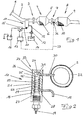
- FIG. 1 The detail of an exhaust system shown in Fig. 1 comprises a connectable via a flange 1 to a manifold 2, a connected via a flange 3 to the front pipe 2 catalyst assembly 4 with an accommodated in a catalyst housing 5 oxidation catalyst unit 6 and via a flange 7 to the catalyst assembly 4 connected filter assembly 8 with a housed in a particulate filter housing 9 particulate filter 10.
- the Vorrohr 2 is relatively close to the flange 3 a fuel evaporation unit 11 assigned, which feeds evaporated diesel fuel in the exhaust pipe 2 flowing through the exhaust stream.
- the fuel evaporation unit 11 communicates with the fuel tank 14 of the vehicle. Furthermore, the fuel evaporation unit 11 is connected via a switch 15 to the power supply 16 of the vehicle.
- the switch 15 is controlled by a constructed in such a known manner control unit 17, which initiates regeneration by evaluating various input variables, in particular of the pressure gradient existing on the particulate filter by the switch 15 closed and - with a defined time delay - the pump 13 is put into operation.
- the fuel evaporation unit 11 comprises an electric heating element in the form of a glow plug 18 in standing Arrangement.
- the electrical connection cable 20 (see Fig. 1) is connected to the electrical connection 19.
- the cylindrical glow plug 21 of the glow plug 18 is surrounded by a jacket tube 23 while maintaining an annular gap 22 having a clear width of 1 mm.
- the jacket tube is sealed at the end by a cover 24, wherein a vapor extraction space 26 is formed by a corresponding distance of the lid 24 to the tip 25 of the glow plug 21.
- To the base 27 of the glow plug 18 through the jacket tube 23 is sealed on the socket 28.
- a helical guide member 29 is housed, which surrounds the glow plug 21 helically.
- the fuel line 12 opens into the jacket tube 23 adjacent to the base 27 of the glow plug 18th
- the end of the fuel vapor injection duct 30 assigned to the front pipe 2 projects into the front pipe 2, specifically in the narrowest cross section of a venturi insert 32 inserted into the front pipe 2.
- the fuel evaporation unit 11 comprises a jacket tube 23 surrounding the insulator 33, which comprises a cladding tube 34 and an existing between the casing tube 23 and the cladding tube 34 space filling insulation 35.
- a temperature sensor 36 is arranged between the oxidation catalyst unit 6 and the particle filter 10. This detects the temperature of the exhaust gas in front of the particle filter; it is connected via a signal line 37 to the control unit 17, which in the regeneration mode controls the delivery rate of the fuel pump 13 feeding the fuel evaporation unit 11 as a function of the determined exhaust gas temperature upstream of the particle filter 10.
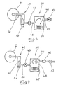
- FIG. 3 illustrates a possibility of connecting a preheating stage 38 to the fuel evaporation unit 11.
- the preheating stage 38 comprises a buffer 39 whose capacity is designed for the required for a single regeneration of the particulate filter amount of fuel.
- the pump 13 fuel is conveyed from the fuel tank of the vehicle into the buffer 39.
- a preheating element 40 is arranged in the form of an electrical resistance heating element. With this, the fuel taken up in the buffer is gradually heated so that its temperature at initiation of regeneration is slightly below the boiling point.
- a valve 42 is arranged, which - as well as the pump 13 - is controlled in accordance with a control unit to initiate the regeneration or end.
- the buffer 39 of the fuel supply nozzle 43 and the fuel outlet nozzle are arranged such that during the regeneration of the particulate filter as little mixing of nachgeSmartten in the buffer fuel with the already preheated fuel, so that it reaches the fuel evaporation unit 11 at the highest possible temperature level.
- the device illustrated in FIG. 4 is suitable for producing and retrievably providing the entire fuel vapor required for the regeneration of the particulate filter "in stock".
- the fuel evaporation unit 11 comprises a pressure vessel 44 with an electrical heater 45 disposed therein. Fuel taken from the fuel tank of the vehicle is supplied to the pressure vessel by means of the pump 13 and via a valve 46. Another valve 47 is connected downstream of the pressure vessel 44. By appropriate action on the heating device 45, the fuel fed into the pressure vessel 44 is gradually evaporated. The resulting vapor 48 is stored in the pressure vessel 44 until initiation of regeneration.
- valve 47 If the valve 47 is opened to initiate the regeneration of the particulate filter, the previously treated fuel vapor 48 flows via the fuel vapor injection channel 30 into the delivery pipe 2.
- a reheater 49 is integrated into the fuel vapor injection channel. This comprises a glow plug 51 inserted in a jacket tube 50, on the surface of the fuel vapor 48 is homogenized and reheated before it enters the exhaust gas stream.
Applications Claiming Priority (3)
| Application Number | Priority Date | Filing Date | Title |
|---|---|---|---|
| DE10225273A DE10225273B4 (de) | 2002-06-07 | 2002-06-07 | Kraftfahrzeug mit einem Diesel-Antriebsmotor |
| DE20218811U DE20218811U1 (de) | 2002-06-07 | 2002-12-05 | Kraftfahrzeug mit einem Diesel-Antriebsmotor |
| EP03011990A EP1369557B1 (fr) | 2002-06-07 | 2003-05-28 | Véhicule entrainé par un moteur diesel comprenant un système d'épuration de gaz d'échappement à régénération discontinue par l'injection des vapeurs de carburant |
Related Parent Applications (1)
| Application Number | Title | Priority Date | Filing Date |
|---|---|---|---|
| EP03011990A Division EP1369557B1 (fr) | 2002-06-07 | 2003-05-28 | Véhicule entrainé par un moteur diesel comprenant un système d'épuration de gaz d'échappement à régénération discontinue par l'injection des vapeurs de carburant |
Publications (2)
| Publication Number | Publication Date |
|---|---|
| EP1643092A1 true EP1643092A1 (fr) | 2006-04-05 |
| EP1643092B1 EP1643092B1 (fr) | 2010-02-10 |
Family
ID=7714634
Family Applications (1)
| Application Number | Title | Priority Date | Filing Date |
|---|---|---|---|
| EP05028734A Expired - Lifetime EP1643092B1 (fr) | 2002-06-07 | 2003-05-28 | Véhicule entraîné par un moteur diesel comprenant un système d'épuration de gaz d'échappement à régénération discontinue par l'injection des vapeurs de carburant |
Country Status (2)
| Country | Link |
|---|---|
| EP (1) | EP1643092B1 (fr) |
| DE (3) | DE10225273B4 (fr) |
Cited By (7)
| Publication number | Priority date | Publication date | Assignee | Title |
|---|---|---|---|---|
| WO2007079832A1 (fr) | 2005-12-29 | 2007-07-19 | Emcon Technologies Germany (Augsburg) Gmbh | Installation de gaz d'echappement de vehicule a moteur et procede pour regenerer un filtre a particules dans une installation de gaz d'echappement de vehicule a moteur |
| WO2008012453A1 (fr) * | 2006-07-26 | 2008-01-31 | Renault S.A.S. | Dispositif de vaporisation de carburant dans une ligne d'echappement |
| FR2908818A1 (fr) * | 2006-11-20 | 2008-05-23 | Renault Sas | Ligne d'echappement de moteur adaptee a homogeneiser la richesse en carburant dans les gaz d'echappement a l'entree des moyens de depollution et de filtrage |
| FR2921438A1 (fr) | 2007-09-25 | 2009-03-27 | Renault Sas | Dispositif de vaporisation de carburant |
| FR2924750A1 (fr) * | 2007-12-05 | 2009-06-12 | Renault Sas | Ligne d'echappement d'un moteur a combustion apte a ameliorer l'homogeneisation du melange des gaz d'echappement . |
| EP2093396A1 (fr) | 2008-02-22 | 2009-08-26 | Ford Global Technologies, LLC | Système d'échappement et procédé pour un tel système |
| EP2302181A4 (fr) * | 2008-05-13 | 2015-05-06 | Isuzu Motors Ltd | Système de purification des gaz d'échappement, et procédé de gestion correspondant |
Families Citing this family (8)
| Publication number | Priority date | Publication date | Assignee | Title |
|---|---|---|---|---|
| US7082753B2 (en) * | 2001-12-03 | 2006-08-01 | Catalytica Energy Systems, Inc. | System and methods for improved emission control of internal combustion engines using pulsed fuel flow |
| WO2004046514A1 (fr) | 2002-11-15 | 2004-06-03 | Catalytica Energy Systems, Inc. | Dispositifs et procedes pour reduire les emissions de nox de moteurs a melange pauvre |
| US8006484B2 (en) | 2005-02-14 | 2011-08-30 | Eaton Corporation | Systems and methods for reducing emissions of internal combustion engines using a fuel processor bypass |
| DE102007025419A1 (de) * | 2007-05-31 | 2008-12-04 | Emitec Gesellschaft Für Emissionstechnologie Mbh | Verfahren zum Betrieb eines Kraftfahrzeuges mit einer Abgas-Heizvorrichtung |
| DE102008026477A1 (de) | 2008-06-03 | 2009-12-10 | Deutz Ag | Abgasnachbehandlungssystem für eine selbstzündende Brennkraftmaschine |
| DE102008051168A1 (de) * | 2008-10-10 | 2010-04-15 | Emitec Gesellschaft Für Emissionstechnologie Mbh | Verfahren zum Betreiben einer Verdampfungseinheit zur Erzeugung gasförmigen Ammoniaks |
| EP2722503B1 (fr) * | 2012-10-19 | 2021-10-13 | Dinex Finland Oy | Amplificateur thermique de gaz d'échappement |
| FR3006709B1 (fr) * | 2013-06-11 | 2015-06-19 | Peugeot Citroen Automobiles Sa | Procede de limitation du vieillissement d' un catalyseur dans une ligne d' echappement de vehicule automobile |
Citations (10)
| Publication number | Priority date | Publication date | Assignee | Title |
|---|---|---|---|---|
| DE2234601A1 (de) * | 1971-07-19 | 1973-02-01 | Ford Werke Ag | Abgasanlage fuer verbrennungskraftmaschinen |
| DE3139565A1 (de) * | 1980-10-06 | 1982-08-05 | Texaco Development Corp., 10650 White Plains, N.Y. | "verfahren zur behandlung eines heissen abgasstromes einer verbrennungskraftmaschine" |
| US4449362A (en) * | 1981-12-02 | 1984-05-22 | Robertshaw Controls Company | Exhaust system for an internal combustion engine, burn-off unit and methods therefor |
| EP0132166A1 (fr) * | 1983-06-16 | 1985-01-23 | Regie Nationale Des Usines Renault | Régénération des filtres à particules notamment pour moteurs Diesel |
| JPH06117224A (ja) * | 1992-09-30 | 1994-04-26 | Mitsubishi Motors Corp | 排気ガス浄化装置 |
| JPH07269329A (ja) * | 1994-03-28 | 1995-10-17 | Mitsubishi Heavy Ind Ltd | 内燃機関の脱硝装置 |
| DE19717544A1 (de) * | 1997-04-25 | 1998-10-29 | Eberspaecher J Gmbh & Co | Verdampferbrenner für ein Heizgerät oder eine thermische Regeneration eines Abgas-Partikelfilters |
| EP0971102A2 (fr) * | 1998-07-10 | 2000-01-12 | Mitsubishi Jidosha Kogyo Kabushiki Kaisha | Système de réduction de NOx pour les gaz d' échappement de combustion |
| DE19855385A1 (de) * | 1998-12-01 | 2000-06-08 | Bosch Gmbh Robert | Vorrichtung zum Nachbehandeln von Abgasen einer Brennkraftmaschine |
| WO2001034950A1 (fr) * | 1999-11-10 | 2001-05-17 | Engelhard Corporation | Procede et appareil pour fournir un reducteur de no¿x? |
Family Cites Families (2)
| Publication number | Priority date | Publication date | Assignee | Title |
|---|---|---|---|---|
| DE19533355A1 (de) * | 1995-09-08 | 1997-03-13 | Wilfried Faerber | Verfahren und Vorrichtung zur Behandlung von Abgasen |
| DE10018792C1 (de) * | 2000-04-15 | 2001-09-13 | Daimler Chrysler Ag | Verfahren und Vorrichtung zur Schadstoffreduktion von Abgasen von Verbrennungsmotoren |
-
2002
- 2002-06-07 DE DE10225273A patent/DE10225273B4/de not_active Expired - Fee Related
- 2002-12-05 DE DE20218811U patent/DE20218811U1/de not_active Expired - Lifetime
-
2003
- 2003-05-28 EP EP05028734A patent/EP1643092B1/fr not_active Expired - Lifetime
- 2003-05-28 DE DE50312417T patent/DE50312417D1/de not_active Expired - Lifetime
Patent Citations (10)
| Publication number | Priority date | Publication date | Assignee | Title |
|---|---|---|---|---|
| DE2234601A1 (de) * | 1971-07-19 | 1973-02-01 | Ford Werke Ag | Abgasanlage fuer verbrennungskraftmaschinen |
| DE3139565A1 (de) * | 1980-10-06 | 1982-08-05 | Texaco Development Corp., 10650 White Plains, N.Y. | "verfahren zur behandlung eines heissen abgasstromes einer verbrennungskraftmaschine" |
| US4449362A (en) * | 1981-12-02 | 1984-05-22 | Robertshaw Controls Company | Exhaust system for an internal combustion engine, burn-off unit and methods therefor |
| EP0132166A1 (fr) * | 1983-06-16 | 1985-01-23 | Regie Nationale Des Usines Renault | Régénération des filtres à particules notamment pour moteurs Diesel |
| JPH06117224A (ja) * | 1992-09-30 | 1994-04-26 | Mitsubishi Motors Corp | 排気ガス浄化装置 |
| JPH07269329A (ja) * | 1994-03-28 | 1995-10-17 | Mitsubishi Heavy Ind Ltd | 内燃機関の脱硝装置 |
| DE19717544A1 (de) * | 1997-04-25 | 1998-10-29 | Eberspaecher J Gmbh & Co | Verdampferbrenner für ein Heizgerät oder eine thermische Regeneration eines Abgas-Partikelfilters |
| EP0971102A2 (fr) * | 1998-07-10 | 2000-01-12 | Mitsubishi Jidosha Kogyo Kabushiki Kaisha | Système de réduction de NOx pour les gaz d' échappement de combustion |
| DE19855385A1 (de) * | 1998-12-01 | 2000-06-08 | Bosch Gmbh Robert | Vorrichtung zum Nachbehandeln von Abgasen einer Brennkraftmaschine |
| WO2001034950A1 (fr) * | 1999-11-10 | 2001-05-17 | Engelhard Corporation | Procede et appareil pour fournir un reducteur de no¿x? |
Non-Patent Citations (2)
| Title |
|---|
| PATENT ABSTRACTS OF JAPAN vol. 018, no. 408 (M - 1647) 29 July 1994 (1994-07-29) * |
| PATENT ABSTRACTS OF JAPAN vol. 1996, no. 02 29 February 1996 (1996-02-29) * |
Cited By (9)
| Publication number | Priority date | Publication date | Assignee | Title |
|---|---|---|---|---|
| WO2007079832A1 (fr) | 2005-12-29 | 2007-07-19 | Emcon Technologies Germany (Augsburg) Gmbh | Installation de gaz d'echappement de vehicule a moteur et procede pour regenerer un filtre a particules dans une installation de gaz d'echappement de vehicule a moteur |
| WO2008012453A1 (fr) * | 2006-07-26 | 2008-01-31 | Renault S.A.S. | Dispositif de vaporisation de carburant dans une ligne d'echappement |
| FR2904362A1 (fr) * | 2006-07-26 | 2008-02-01 | Renault Sas | Dispositif de vaporisation de carburant dans une ligne d'echappement du vehicule |
| FR2904361A1 (fr) * | 2006-07-26 | 2008-02-01 | Renault Sas | Dispositif de vaporisation de carburant dans une ligne d'echappement de moteur thermique |
| FR2908818A1 (fr) * | 2006-11-20 | 2008-05-23 | Renault Sas | Ligne d'echappement de moteur adaptee a homogeneiser la richesse en carburant dans les gaz d'echappement a l'entree des moyens de depollution et de filtrage |
| FR2921438A1 (fr) | 2007-09-25 | 2009-03-27 | Renault Sas | Dispositif de vaporisation de carburant |
| FR2924750A1 (fr) * | 2007-12-05 | 2009-06-12 | Renault Sas | Ligne d'echappement d'un moteur a combustion apte a ameliorer l'homogeneisation du melange des gaz d'echappement . |
| EP2093396A1 (fr) | 2008-02-22 | 2009-08-26 | Ford Global Technologies, LLC | Système d'échappement et procédé pour un tel système |
| EP2302181A4 (fr) * | 2008-05-13 | 2015-05-06 | Isuzu Motors Ltd | Système de purification des gaz d'échappement, et procédé de gestion correspondant |
Also Published As
| Publication number | Publication date |
|---|---|
| EP1643092B1 (fr) | 2010-02-10 |
| DE20218811U1 (de) | 2003-03-06 |
| DE10225273B4 (de) | 2006-06-14 |
| DE10225273A1 (de) | 2004-01-08 |
| DE50312417D1 (de) | 2010-03-25 |
Similar Documents
| Publication | Publication Date | Title |
|---|---|---|
| DE10256769B4 (de) | Kraftfahrzeug mit einem Diesel-Antriebsmotor | |
| EP1369557B1 (fr) | Véhicule entrainé par un moteur diesel comprenant un système d'épuration de gaz d'échappement à régénération discontinue par l'injection des vapeurs de carburant | |
| DE102010052534B4 (de) | Luftunterstützter Fluidinjektor sowie Injektionssystem und Verbrennungsmotor mit Abgasbehandlungssystem, die diesen enthalten | |
| EP1244512B1 (fr) | Dispositif et procede de traitement subsequent de gaz d'echappement | |
| EP1643092B1 (fr) | Véhicule entraîné par un moteur diesel comprenant un système d'épuration de gaz d'échappement à régénération discontinue par l'injection des vapeurs de carburant | |
| EP3660287B1 (fr) | Système de post-traitement des gaz d'échappement ainsi que procédé de post-traitement des gaz d'échappement d'un moteur à combustion interne | |
| DE102008026477A1 (de) | Abgasnachbehandlungssystem für eine selbstzündende Brennkraftmaschine | |
| DE102018100240A1 (de) | Abgasnachbehandlungssystem und Verfahren zur Abgasnachbehandlung eines Verbrennungsmotors | |
| DE102012024260A1 (de) | Verfahren und Vorrichtung zur Anhebung der Abgastemperatur im Abgastrakt einer turboaufgeladenen Brennkraftmaschine | |
| DE102005062398A1 (de) | Regenerieren eines Partikelfilters mit einer oxidationskatalytischen Beschichtung | |
| WO2006125525A1 (fr) | Systeme d'echappement d'un moteur a combustion interne | |
| WO2007025803A1 (fr) | Systeme d'injection de carburant a emissions polluantes reduites | |
| EP0806553A2 (fr) | Méthode de purification de gaz d'échappement de moteurs diesel | |
| WO2019170388A1 (fr) | Procédé servant à faire fonctionner un filtre à particules d'un véhicule, et filtre à particules pour un moteur à combustion interne d'un véhicule | |
| DE102017222235A1 (de) | Verfahren und Vorrichtung zur Aufheizung einer Abgasreinigungsanlage einer Brennkraftmaschine | |
| DE60210631T2 (de) | Verfahren zur Regenerierung einer Abgasfiltervorrichtung für Dieselmotoren und Vorrichtung dafür | |
| DE10120973B4 (de) | Abgasreinigungsanlage mit Partikelfiltermitteln und Regenerationsverfahren für Partikelfiltermittel | |
| DE102004062208A1 (de) | Abgasanlage für ein Kraftfahrzeug mit wenigstens einem Abgasreinigungssystem und Verfahren zur Regeneration eines solchen | |
| EP3770386A1 (fr) | Système de post-traitement des gaz d'échappement et procédé de post-traitement des gaz d'échappement d'un moteur à combustion interne | |
| DE10361220B4 (de) | Verfahren zum Regenerieren eines Partikelfilters | |
| DE112008001111T5 (de) | Regenerationsvorrichtung, die eine luftunterstützte Treibstoffdüse aufweist | |
| EP1026380B1 (fr) | Moteur à combustion avec un dispositif d'alimentation d'un moyen de combustion | |
| DE102019008964A1 (de) | Abgasanlage für eine Verbrennungskraftmaschine eines Kraftfahrzeugs, insbesondere eines Kraftwagens | |
| DE102019212883A1 (de) | Mischvorrichtung | |
| DE102019006494B4 (de) | Abgasanlage für eine Verbrennungskraftmaschine eines Kraftfahrzeugs, Antriebseinrichtung für ein Kraftfahrzeug sowie Kraftfahrzeug |
Legal Events
| Date | Code | Title | Description |
|---|---|---|---|
| PUAI | Public reference made under article 153(3) epc to a published international application that has entered the european phase |
Free format text: ORIGINAL CODE: 0009012 |
|
| AC | Divisional application: reference to earlier application |
Ref document number: 1369557 Country of ref document: EP Kind code of ref document: P |
|
| AK | Designated contracting states |
Kind code of ref document: A1 Designated state(s): DE FR IT |
|
| 17P | Request for examination filed |
Effective date: 20060907 |
|
| 17Q | First examination report despatched |
Effective date: 20061010 |
|
| AKX | Designation fees paid |
Designated state(s): DE FR IT |
|
| 18D | Application deemed to be withdrawn |
Effective date: 20070421 |
|
| D18D | Application deemed to be withdrawn (deleted) | ||
| RAP1 | Party data changed (applicant data changed or rights of an application transferred) |
Owner name: EMCON TECHNOLOGIES GERMANY (AUGSBURG) GMBH |
|
| GRAP | Despatch of communication of intention to grant a patent |
Free format text: ORIGINAL CODE: EPIDOSNIGR1 |
|
| GRAS | Grant fee paid |
Free format text: ORIGINAL CODE: EPIDOSNIGR3 |
|
| GRAA | (expected) grant |
Free format text: ORIGINAL CODE: 0009210 |
|
| AC | Divisional application: reference to earlier application |
Ref document number: 1369557 Country of ref document: EP Kind code of ref document: P |
|
| AK | Designated contracting states |
Kind code of ref document: B1 Designated state(s): DE FR IT |
|
| REF | Corresponds to: |
Ref document number: 50312417 Country of ref document: DE Date of ref document: 20100325 Kind code of ref document: P |
|
| PLBE | No opposition filed within time limit |
Free format text: ORIGINAL CODE: 0009261 |
|
| STAA | Information on the status of an ep patent application or granted ep patent |
Free format text: STATUS: NO OPPOSITION FILED WITHIN TIME LIMIT |
|
| 26N | No opposition filed |
Effective date: 20101111 |
|
| PG25 | Lapsed in a contracting state [announced via postgrant information from national office to epo] |
Ref country code: IT Free format text: LAPSE BECAUSE OF FAILURE TO SUBMIT A TRANSLATION OF THE DESCRIPTION OR TO PAY THE FEE WITHIN THE PRESCRIBED TIME-LIMIT Effective date: 20100210 |
|
| REG | Reference to a national code |
Ref country code: FR Ref legal event code: PLFP Year of fee payment: 14 |
|
| REG | Reference to a national code |
Ref country code: FR Ref legal event code: PLFP Year of fee payment: 15 |
|
| REG | Reference to a national code |
Ref country code: FR Ref legal event code: PLFP Year of fee payment: 16 |
|
| PGFP | Annual fee paid to national office [announced via postgrant information from national office to epo] |
Ref country code: DE Payment date: 20210421 Year of fee payment: 19 Ref country code: FR Payment date: 20210421 Year of fee payment: 19 |
|
| REG | Reference to a national code |
Ref country code: DE Ref legal event code: R119 Ref document number: 50312417 Country of ref document: DE |
|
| PG25 | Lapsed in a contracting state [announced via postgrant information from national office to epo] |
Ref country code: FR Free format text: LAPSE BECAUSE OF NON-PAYMENT OF DUE FEES Effective date: 20220531 |
|
| PG25 | Lapsed in a contracting state [announced via postgrant information from national office to epo] |
Ref country code: DE Free format text: LAPSE BECAUSE OF NON-PAYMENT OF DUE FEES Effective date: 20221201 |