EP1642631A1 - Druckfilter für Aquarien und Teiche mit Bürstenelemente zum Reinigen des Filterelements - Google Patents
Druckfilter für Aquarien und Teiche mit Bürstenelemente zum Reinigen des Filterelements Download PDFInfo
- Publication number
- EP1642631A1 EP1642631A1 EP04425734A EP04425734A EP1642631A1 EP 1642631 A1 EP1642631 A1 EP 1642631A1 EP 04425734 A EP04425734 A EP 04425734A EP 04425734 A EP04425734 A EP 04425734A EP 1642631 A1 EP1642631 A1 EP 1642631A1
- Authority
- EP
- European Patent Office
- Prior art keywords
- filter according
- brushing
- brushing element
- exposed surface
- container
- Prior art date
- Legal status (The legal status is an assumption and is not a legal conclusion. Google has not performed a legal analysis and makes no representation as to the accuracy of the status listed.)
- Granted
Links
- 230000001680 brushing effect Effects 0.000 title claims abstract description 45
- 238000001914 filtration Methods 0.000 title claims abstract description 25
- 238000004140 cleaning Methods 0.000 title description 5
- 239000012535 impurity Substances 0.000 claims abstract description 11
- 239000007788 liquid Substances 0.000 claims abstract description 11
- 230000000717 retained effect Effects 0.000 claims abstract description 4
- 239000000463 material Substances 0.000 claims description 5
- 229920003023 plastic Polymers 0.000 claims description 3
- 239000004033 plastic Substances 0.000 claims description 3
- 229920002635 polyurethane Polymers 0.000 claims description 3
- 239000004814 polyurethane Substances 0.000 claims description 3
- 230000004913 activation Effects 0.000 claims 1
- XLYOFNOQVPJJNP-UHFFFAOYSA-N water Substances O XLYOFNOQVPJJNP-UHFFFAOYSA-N 0.000 abstract description 6
- 230000003213 activating effect Effects 0.000 description 1
- 230000000694 effects Effects 0.000 description 1
- 239000012530 fluid Substances 0.000 description 1
- 230000010354 integration Effects 0.000 description 1
- 239000002245 particle Substances 0.000 description 1
- 239000011236 particulate material Substances 0.000 description 1
- 230000000750 progressive effect Effects 0.000 description 1
- 230000009467 reduction Effects 0.000 description 1
Images


Classifications
-
- B—PERFORMING OPERATIONS; TRANSPORTING
- B01—PHYSICAL OR CHEMICAL PROCESSES OR APPARATUS IN GENERAL
- B01D—SEPARATION
- B01D29/00—Filters with filtering elements stationary during filtration, e.g. pressure or suction filters, not covered by groups B01D24/00 - B01D27/00; Filtering elements therefor
- B01D29/11—Filters with filtering elements stationary during filtration, e.g. pressure or suction filters, not covered by groups B01D24/00 - B01D27/00; Filtering elements therefor with bag, cage, hose, tube, sleeve or like filtering elements
- B01D29/13—Supported filter elements
- B01D29/15—Supported filter elements arranged for inward flow filtration
-
- A—HUMAN NECESSITIES
- A01—AGRICULTURE; FORESTRY; ANIMAL HUSBANDRY; HUNTING; TRAPPING; FISHING
- A01K—ANIMAL HUSBANDRY; CARE OF BIRDS, FISHES, INSECTS; FISHING; REARING OR BREEDING ANIMALS, NOT OTHERWISE PROVIDED FOR; NEW BREEDS OF ANIMALS
- A01K63/00—Receptacles for live fish, e.g. aquaria; Terraria
- A01K63/04—Arrangements for treating water specially adapted to receptacles for live fish
- A01K63/045—Filters for aquaria
-
- B—PERFORMING OPERATIONS; TRANSPORTING
- B01—PHYSICAL OR CHEMICAL PROCESSES OR APPARATUS IN GENERAL
- B01D—SEPARATION
- B01D29/00—Filters with filtering elements stationary during filtration, e.g. pressure or suction filters, not covered by groups B01D24/00 - B01D27/00; Filtering elements therefor
- B01D29/50—Filters with filtering elements stationary during filtration, e.g. pressure or suction filters, not covered by groups B01D24/00 - B01D27/00; Filtering elements therefor with multiple filtering elements, characterised by their mutual disposition
- B01D29/52—Filters with filtering elements stationary during filtration, e.g. pressure or suction filters, not covered by groups B01D24/00 - B01D27/00; Filtering elements therefor with multiple filtering elements, characterised by their mutual disposition in parallel connection
- B01D29/54—Filters with filtering elements stationary during filtration, e.g. pressure or suction filters, not covered by groups B01D24/00 - B01D27/00; Filtering elements therefor with multiple filtering elements, characterised by their mutual disposition in parallel connection arranged concentrically or coaxially
-
- B—PERFORMING OPERATIONS; TRANSPORTING
- B01—PHYSICAL OR CHEMICAL PROCESSES OR APPARATUS IN GENERAL
- B01D—SEPARATION
- B01D29/00—Filters with filtering elements stationary during filtration, e.g. pressure or suction filters, not covered by groups B01D24/00 - B01D27/00; Filtering elements therefor
- B01D29/62—Regenerating the filter material in the filter
- B01D29/64—Regenerating the filter material in the filter by scrapers, brushes, nozzles, or the like, acting on the cake side of the filtering element
- B01D29/6407—Regenerating the filter material in the filter by scrapers, brushes, nozzles, or the like, acting on the cake side of the filtering element brushes
- B01D29/6423—Regenerating the filter material in the filter by scrapers, brushes, nozzles, or the like, acting on the cake side of the filtering element brushes with a translational movement with respect to the filtering element
Definitions
- the present invention relates, in its more general aspect, to a pressure filter for aquariology, for retaining impurities of a liquid intended for ponds, aquaria and the like.
- the filter is of the type comprising a substantially glass-like container closed by means of a cover, a liquid path extended in the container between an inlet opening and an outlet opening, and a filtering body arranged along the liquid path and having a surface exposed to the liquid whereon the impurities are retained.
- the pressure filter according to the invention is provided with means for cleaning the filtering body, which comprise a brushing element mounted in the container in a guided way with to and from movement along the exposed surface.
- brushing element generally means an element able to scrape or scratch the exposed surface thanks to a continuous and alternated movement.
- the pressure filters of the above mentioned type mainly perform the function of mechanically filtering the water, by removing the impurities such as the suspended material, the particulate and the filth particles. Normally this function is performed by a series of sponges, realised with expanded plastic material with communicating cells, preferably with polyurethane.
- the technical problem underlying the present invention is that of devising a pressure filter having such structural and functional characteristics as to overcome the above-cited drawback.
- 10 globally and schematically indicates a pressure filter for aquariology realised according to the present invention for retaining impurities of the water intended for aquaria or ponds.
- the filter 10 is thus intended for uses, which provide the filtration of the water liquid, but nothing forbids that such filter can be used with other typologies of liquids.
- the filter 10 comprises a container 12, of prefixed axis X and having substantially glass-like shape closed by means of a cover 14.
- the filter 10 further comprises a fluid path, schematically indicated with the reference number 15, which is extended in the container 12 between an inlet opening 16 and an outlet opening 17.
- the container 12 comprises an adduction fitting and, respectively, a feed fitting, of the known type and not shown in the drawings, for the connection with a pond, in case of use with re-circulation, or with a dump.
- the filter 10 also comprises a filtering body 18 placed along the path 15 and having a surface 19 exposed to the liquid whereon the impurities of the water are retained.
- the container 12 centrally comprises a grilled tube 20 in communication with the outlet opening 17 through a central conduit 21.
- the filtering body is housed which, in the here described example embodiment comprises a plurality of sponges 18 realised for example with polyurethane with open cell.
- the sponges 18 are circularly ring-like shaped and stacked one on the other around the grilled tube 20 to fill the container 12 and form an annular chamber 22 put in communication with the inlet opening 16.
- the above mentioned liquid path 15 extends, starting from the inlet opening 16, with a substantially radial direction from the annular chamber 22 towards the grilled tube 20 crossing the whole circular surface 19 of the sponges 18.
- the filter 10 also comprises brushing means mounted guided inside the container 12 along the exposed surface with a to and from linear movement along an axis Y, and respectively Y', substantially parallel to the exposed surface.
- the brushing means comprise, in the specific case, two brushing elements 31, which can be housed in the annular chamber 22 on diametrically opposite parts with respect to the sponges 18.
- Each brushing elements 31 is preferably shaped in the form of a semi-ring (figures 3 And 4) and it comprises on a side 33 facing the surface 19 a plurality of tabs 34, flanked one with the other along the inside of the whole semi-ring 31.
- they are two independent semi-rings 31 which coaxially surround the sponges 18, and substantially form a ring, which closes these latter.
- each semi-ring 31 is angularly mobile against the surface 19.
- each semi-ring 31 is angularly mobile exactly around the above-mentioned same axis Y, and respectively Y', along which, as it has been said, it is guided with to and from movement.
- the filter 10 comprises a pair of control rods 36 each of which is arranged swivelling around the axis Y and, respectively Y'.
- control rods 36 are mounted passing through respective calibrated holes 38, equipped with tight washer, which are made in the cover 14 of the filter 10.
- a first end of the rod 36 is integrally fixed, substantially orthogonal, to the respective semi-ring 31.
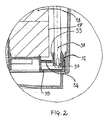
- a pin 37 (figure 2) is for example provided.
- a second end, opposite with respect to the first one, is placed outside the container 12 and it is associated with a grip handle 40.
- each semi-ring 31 is thus mobile from a first position in correspondence with a bottom wall 35 of the container 12 and a second position near the cover 14, and at the same time it can be angularly moved around the axis Y and, respectively Y', for pressing against the exposed surface 19.
- the inner diameter of the two semi-rings 31 is smaller than the outer diameter of the sponges 18, and this allows to improve the brushing action against the surface 19.
- the tabs 34 are also realised with plastic material and with the thickness of some tens of mm, so as to be flexible and to adapt both to the above to and from movement, and to the movement of the semi-ring 31 against the surface 19.
- each control rod 36 is also preferably fixed in a substantially mean and central area of the respective semi-ring 31, for dividing this latter in two portions 31a and 31b.
- the two semi-rings 31 rotate around the respective axes Y, Y' towards the surface 19 and they press now with the one, now with the other portion 31a and, respectively, 31b against the surface 19.
- the main advantage of the filter according to the present invention stays in that it can adjust the position and the distance of the brushing element against the exposed surface maintaining it in constant pressing contact.
- the filtering body is made of sponges or similar porous elements, which, exactly for the properties of the material they are realised with, are subject to wear mainly due to the effect of time, of the water action, and of the pressures the container undergoes. As a consequence, with the passage of time these sponges undergo a remarkable dimension decrease.
- the shown solution also offers the advantage that a user, simply acting on the handles, can easily perform the angular shift.
- the rotation of the control rods can be also performed simultaneously to the linear to and from movement, and this allows combining the brushing action along the surface with the shift of the brushing elements against it.
- the two semi-rings also offer the advantage of brushing a whole circular surface of the sponges, as if it were a single ring.
- a further advantage stays in the mean position of each rod with respect to the corresponding semi-ring. This allows, by rotating the rods now in a sense, now in the other, to approach to the exposed surface substantially the semi-ring inside and to obtain an almost complete brushing of the surface of the sponges.
- control rod is fixed in an eccentric position with respect to the semi-ring in correspondence with one of the terminal portions of the brushing element.
- the brushing element is angularly shifted by means of rotation in a single rotation sense against the surface of the filtering body.
- Spring means can be provided for maintaining the brushing element in an angularly shifted position.
Priority Applications (4)
| Application Number | Priority Date | Filing Date | Title |
|---|---|---|---|
| EP04425734A EP1642631B1 (de) | 2004-09-30 | 2004-09-30 | Druckfilter für Aquarien und Teiche mit Bürstenelemente zum Reinigen des Filterelements |
| DE602004022050T DE602004022050D1 (de) | 2004-09-30 | 2004-09-30 | Druckfilter für Aquarien und Teiche mit Bürstenelemente zum Reinigen des Filterelements |
| CA002521387A CA2521387A1 (en) | 2004-09-30 | 2005-09-28 | Pressure filter for aquariology |
| US11/237,518 US7399407B2 (en) | 2004-09-30 | 2005-09-28 | Pressure filter for aquariology |
Applications Claiming Priority (1)
| Application Number | Priority Date | Filing Date | Title |
|---|---|---|---|
| EP04425734A EP1642631B1 (de) | 2004-09-30 | 2004-09-30 | Druckfilter für Aquarien und Teiche mit Bürstenelemente zum Reinigen des Filterelements |
Publications (2)
| Publication Number | Publication Date |
|---|---|
| EP1642631A1 true EP1642631A1 (de) | 2006-04-05 |
| EP1642631B1 EP1642631B1 (de) | 2009-07-15 |
Family
ID=34932797
Family Applications (1)
| Application Number | Title | Priority Date | Filing Date |
|---|---|---|---|
| EP04425734A Active EP1642631B1 (de) | 2004-09-30 | 2004-09-30 | Druckfilter für Aquarien und Teiche mit Bürstenelemente zum Reinigen des Filterelements |
Country Status (4)
| Country | Link |
|---|---|
| US (1) | US7399407B2 (de) |
| EP (1) | EP1642631B1 (de) |
| CA (1) | CA2521387A1 (de) |
| DE (1) | DE602004022050D1 (de) |
Cited By (2)
| Publication number | Priority date | Publication date | Assignee | Title |
|---|---|---|---|---|
| US7276169B2 (en) * | 2004-04-05 | 2007-10-02 | Askoll Holding S.R.L. | Method for filtering water in an aquarium, a water cultivation tank and similar water bonds, and corresponding filtering system |
| CN105582725A (zh) * | 2016-03-10 | 2016-05-18 | 中国农业科学院农田灌溉研究所 | 一种漂浮式微灌过滤系统 |
Families Citing this family (6)
| Publication number | Priority date | Publication date | Assignee | Title |
|---|---|---|---|---|
| US20110079562A1 (en) * | 2009-10-02 | 2011-04-07 | James Alexander Stark | Liquid separation using relative motion and fluid effects |
| PL234666B1 (pl) * | 2018-04-26 | 2020-03-31 | Aquael Janusz Jankiewicz Spolka Z Ograniczona Odpowiedzialnoscia | Filtr wody do akwarium |
| CN109220980A (zh) * | 2018-10-15 | 2019-01-18 | 合肥亿翔智能制造有限公司 | 一种鱼塘清理系统及控制系统 |
| CN113041672A (zh) * | 2019-12-29 | 2021-06-29 | 广西国宏智鸿环保科技集团有限公司 | 一种净水设备使用的pp棉过滤器 |
| CN114275402B (zh) * | 2021-11-22 | 2022-10-28 | 浙江微盾环保科技股份有限公司 | 一种医疗废物处理的水循环装置 |
| CN114377472B (zh) * | 2022-01-13 | 2023-12-22 | 粒软(江苏)科技有限公司 | 一种水族馆过滤用联动机构及水族馆过滤器装置 |
Citations (5)
| Publication number | Priority date | Publication date | Assignee | Title |
|---|---|---|---|---|
| CH394124A (de) | 1961-11-13 | 1965-06-30 | Katadyn Ges Mbh Deutsche | Vorrichtung zum Reinigen stehend angeordneter Filterkerzen |
| FR2234913A1 (en) * | 1973-06-30 | 1975-01-24 | Bamag Verfahrenstechnik Gmbh | Cleaning a cartridge filter - using a plate which moves scrapers over the cartridge surfaces |
| GB2007104A (en) * | 1977-11-05 | 1979-05-16 | Krause W | Device for cleaning filter pores of an outer wall of a cylindrical drainage filter |
| DE4307472A1 (de) * | 1993-03-10 | 1994-11-17 | Knecht Filterwerke Gmbh | Filter für Flüssigkeiten, Pasten oder andere hochviskose Medien |
| DE19630652A1 (de) * | 1996-07-30 | 1998-02-05 | Knecht Filterwerke Gmbh | Filter für Flüssigkeiten, Pasten oder andere hochviskose Medien |
Family Cites Families (3)
| Publication number | Priority date | Publication date | Assignee | Title |
|---|---|---|---|---|
| US1548160A (en) * | 1922-04-20 | 1925-08-04 | Wm B Scaife & Sons Company | Apparatus for filtering and softening water |
| DE394124C (de) * | 1922-08-30 | 1924-04-14 | Waggonfabrik L Steinfurt G M B | Achsenanordnung fuer vierachsige Eisenbahnwagen |
| US4883587A (en) * | 1988-10-13 | 1989-11-28 | Leveen Harry H | Polyurethane iodine sponge swimming pool filter |
-
2004
- 2004-09-30 DE DE602004022050T patent/DE602004022050D1/de active Active
- 2004-09-30 EP EP04425734A patent/EP1642631B1/de active Active
-
2005
- 2005-09-28 CA CA002521387A patent/CA2521387A1/en not_active Abandoned
- 2005-09-28 US US11/237,518 patent/US7399407B2/en active Active
Patent Citations (5)
| Publication number | Priority date | Publication date | Assignee | Title |
|---|---|---|---|---|
| CH394124A (de) | 1961-11-13 | 1965-06-30 | Katadyn Ges Mbh Deutsche | Vorrichtung zum Reinigen stehend angeordneter Filterkerzen |
| FR2234913A1 (en) * | 1973-06-30 | 1975-01-24 | Bamag Verfahrenstechnik Gmbh | Cleaning a cartridge filter - using a plate which moves scrapers over the cartridge surfaces |
| GB2007104A (en) * | 1977-11-05 | 1979-05-16 | Krause W | Device for cleaning filter pores of an outer wall of a cylindrical drainage filter |
| DE4307472A1 (de) * | 1993-03-10 | 1994-11-17 | Knecht Filterwerke Gmbh | Filter für Flüssigkeiten, Pasten oder andere hochviskose Medien |
| DE19630652A1 (de) * | 1996-07-30 | 1998-02-05 | Knecht Filterwerke Gmbh | Filter für Flüssigkeiten, Pasten oder andere hochviskose Medien |
Cited By (3)
| Publication number | Priority date | Publication date | Assignee | Title |
|---|---|---|---|---|
| US7276169B2 (en) * | 2004-04-05 | 2007-10-02 | Askoll Holding S.R.L. | Method for filtering water in an aquarium, a water cultivation tank and similar water bonds, and corresponding filtering system |
| CN105582725A (zh) * | 2016-03-10 | 2016-05-18 | 中国农业科学院农田灌溉研究所 | 一种漂浮式微灌过滤系统 |
| CN105582725B (zh) * | 2016-03-10 | 2018-01-12 | 中国农业科学院农田灌溉研究所 | 一种漂浮式微灌过滤系统 |
Also Published As
| Publication number | Publication date |
|---|---|
| US20060157395A1 (en) | 2006-07-20 |
| CA2521387A1 (en) | 2006-03-30 |
| US7399407B2 (en) | 2008-07-15 |
| DE602004022050D1 (de) | 2009-08-27 |
| EP1642631B1 (de) | 2009-07-15 |
Similar Documents
| Publication | Publication Date | Title |
|---|---|---|
| US7399407B2 (en) | Pressure filter for aquariology | |
| US8828228B2 (en) | In-line strainer | |
| US4277333A (en) | Portable water filtration system | |
| EP0482134A1 (de) | Verfahren und Vorrichtung zur Filtration von Fluiden | |
| CN105709492B (zh) | 滤芯和具有其的水处理装置 | |
| US3527351A (en) | Fluid filtering apparatus | |
| EP2311317B1 (de) | Wasserrohrreinigungsvorrichtung für wassertankfilter | |
| DE3716765A1 (de) | Membran mit magnet | |
| WO2004039474A3 (en) | Biological fluid filter | |
| KR200191317Y1 (ko) | 휴대용 정수기 | |
| US7560021B2 (en) | Selector valve of a pressure filter for aquariums or ponds | |
| CN208829399U (zh) | 一种饮用水净化器集成滤芯 | |
| CN110744849A (zh) | 一种生物制剂的提取设备 | |
| CN108815905A (zh) | 一种自动挤压污水处理装置 | |
| KR100367233B1 (ko) | 정수기 | |
| WO2007055483A1 (en) | Pore size controllable filter | |
| CN219248948U (zh) | 一种底排组件 | |
| CN208049718U (zh) | 一种自清洁式管式陶瓷膜 | |
| CN207569328U (zh) | 一种带过滤装置的单孔面盆龙头 | |
| JP4471587B2 (ja) | 流路切り替え装置 | |
| RU77558U1 (ru) | Фильтрующий элемент | |
| CN215310571U (zh) | 一种多级复合式精密过滤器 | |
| CN214699286U (zh) | 一种龙头净水器 | |
| SU1643050A1 (ru) | Самоочищающийс фильтр | |
| KR102642484B1 (ko) | 양방향 스트레이너 |
Legal Events
| Date | Code | Title | Description |
|---|---|---|---|
| PUAI | Public reference made under article 153(3) epc to a published international application that has entered the european phase |
Free format text: ORIGINAL CODE: 0009012 |
|
| AK | Designated contracting states |
Kind code of ref document: A1 Designated state(s): AT BE BG CH CY CZ DE DK EE ES FI FR GB GR HU IE IT LI LU MC NL PL PT RO SE SI SK TR |
|
| AX | Request for extension of the european patent |
Extension state: AL HR LT LV MK |
|
| 17P | Request for examination filed |
Effective date: 20061004 |
|
| AKX | Designation fees paid |
Designated state(s): AT BE BG CH CY CZ DE DK EE ES FI FR GB GR HU IE IT LI LU MC NL PL PT RO SE SI SK TR |
|
| 17Q | First examination report despatched |
Effective date: 20070919 |
|
| GRAP | Despatch of communication of intention to grant a patent |
Free format text: ORIGINAL CODE: EPIDOSNIGR1 |
|
| GRAS | Grant fee paid |
Free format text: ORIGINAL CODE: EPIDOSNIGR3 |
|
| GRAA | (expected) grant |
Free format text: ORIGINAL CODE: 0009210 |
|
| AK | Designated contracting states |
Kind code of ref document: B1 Designated state(s): AT BE BG CH CY CZ DE DK EE ES FI FR GB GR HU IE IT LI LU MC NL PL PT RO SE SI SK TR |
|
| REG | Reference to a national code |
Ref country code: CH Ref legal event code: EP Ref country code: GB Ref legal event code: FG4D |
|
| REG | Reference to a national code |
Ref country code: IE Ref legal event code: FG4D |
|
| REF | Corresponds to: |
Ref document number: 602004022050 Country of ref document: DE Date of ref document: 20090827 Kind code of ref document: P |
|
| NLV1 | Nl: lapsed or annulled due to failure to fulfill the requirements of art. 29p and 29m of the patents act | ||
| PG25 | Lapsed in a contracting state [announced via postgrant information from national office to epo] |
Ref country code: FI Free format text: LAPSE BECAUSE OF FAILURE TO SUBMIT A TRANSLATION OF THE DESCRIPTION OR TO PAY THE FEE WITHIN THE PRESCRIBED TIME-LIMIT Effective date: 20090715 Ref country code: AT Free format text: LAPSE BECAUSE OF FAILURE TO SUBMIT A TRANSLATION OF THE DESCRIPTION OR TO PAY THE FEE WITHIN THE PRESCRIBED TIME-LIMIT Effective date: 20090715 Ref country code: SE Free format text: LAPSE BECAUSE OF FAILURE TO SUBMIT A TRANSLATION OF THE DESCRIPTION OR TO PAY THE FEE WITHIN THE PRESCRIBED TIME-LIMIT Effective date: 20090715 Ref country code: ES Free format text: LAPSE BECAUSE OF FAILURE TO SUBMIT A TRANSLATION OF THE DESCRIPTION OR TO PAY THE FEE WITHIN THE PRESCRIBED TIME-LIMIT Effective date: 20091026 |
|
| PG25 | Lapsed in a contracting state [announced via postgrant information from national office to epo] |
Ref country code: SI Free format text: LAPSE BECAUSE OF FAILURE TO SUBMIT A TRANSLATION OF THE DESCRIPTION OR TO PAY THE FEE WITHIN THE PRESCRIBED TIME-LIMIT Effective date: 20090715 Ref country code: NL Free format text: LAPSE BECAUSE OF FAILURE TO SUBMIT A TRANSLATION OF THE DESCRIPTION OR TO PAY THE FEE WITHIN THE PRESCRIBED TIME-LIMIT Effective date: 20090715 Ref country code: PL Free format text: LAPSE BECAUSE OF FAILURE TO SUBMIT A TRANSLATION OF THE DESCRIPTION OR TO PAY THE FEE WITHIN THE PRESCRIBED TIME-LIMIT Effective date: 20090715 |
|
| PG25 | Lapsed in a contracting state [announced via postgrant information from national office to epo] |
Ref country code: BG Free format text: LAPSE BECAUSE OF FAILURE TO SUBMIT A TRANSLATION OF THE DESCRIPTION OR TO PAY THE FEE WITHIN THE PRESCRIBED TIME-LIMIT Effective date: 20091015 Ref country code: PT Free format text: LAPSE BECAUSE OF FAILURE TO SUBMIT A TRANSLATION OF THE DESCRIPTION OR TO PAY THE FEE WITHIN THE PRESCRIBED TIME-LIMIT Effective date: 20091115 |
|
| PG25 | Lapsed in a contracting state [announced via postgrant information from national office to epo] |
Ref country code: CZ Free format text: LAPSE BECAUSE OF FAILURE TO SUBMIT A TRANSLATION OF THE DESCRIPTION OR TO PAY THE FEE WITHIN THE PRESCRIBED TIME-LIMIT Effective date: 20090715 Ref country code: MC Free format text: LAPSE BECAUSE OF NON-PAYMENT OF DUE FEES Effective date: 20090930 Ref country code: DK Free format text: LAPSE BECAUSE OF FAILURE TO SUBMIT A TRANSLATION OF THE DESCRIPTION OR TO PAY THE FEE WITHIN THE PRESCRIBED TIME-LIMIT Effective date: 20090715 Ref country code: RO Free format text: LAPSE BECAUSE OF FAILURE TO SUBMIT A TRANSLATION OF THE DESCRIPTION OR TO PAY THE FEE WITHIN THE PRESCRIBED TIME-LIMIT Effective date: 20090715 Ref country code: EE Free format text: LAPSE BECAUSE OF FAILURE TO SUBMIT A TRANSLATION OF THE DESCRIPTION OR TO PAY THE FEE WITHIN THE PRESCRIBED TIME-LIMIT Effective date: 20090715 |
|
| REG | Reference to a national code |
Ref country code: CH Ref legal event code: PL |
|
| PLBE | No opposition filed within time limit |
Free format text: ORIGINAL CODE: 0009261 |
|
| STAA | Information on the status of an ep patent application or granted ep patent |
Free format text: STATUS: NO OPPOSITION FILED WITHIN TIME LIMIT |
|
| PG25 | Lapsed in a contracting state [announced via postgrant information from national office to epo] |
Ref country code: SK Free format text: LAPSE BECAUSE OF FAILURE TO SUBMIT A TRANSLATION OF THE DESCRIPTION OR TO PAY THE FEE WITHIN THE PRESCRIBED TIME-LIMIT Effective date: 20090715 Ref country code: BE Free format text: LAPSE BECAUSE OF FAILURE TO SUBMIT A TRANSLATION OF THE DESCRIPTION OR TO PAY THE FEE WITHIN THE PRESCRIBED TIME-LIMIT Effective date: 20090715 |
|
| 26N | No opposition filed |
Effective date: 20100416 |
|
| PG25 | Lapsed in a contracting state [announced via postgrant information from national office to epo] |
Ref country code: IE Free format text: LAPSE BECAUSE OF NON-PAYMENT OF DUE FEES Effective date: 20090930 |
|
| PG25 | Lapsed in a contracting state [announced via postgrant information from national office to epo] |
Ref country code: GR Free format text: LAPSE BECAUSE OF FAILURE TO SUBMIT A TRANSLATION OF THE DESCRIPTION OR TO PAY THE FEE WITHIN THE PRESCRIBED TIME-LIMIT Effective date: 20091016 Ref country code: LI Free format text: LAPSE BECAUSE OF NON-PAYMENT OF DUE FEES Effective date: 20090930 Ref country code: CH Free format text: LAPSE BECAUSE OF NON-PAYMENT OF DUE FEES Effective date: 20090930 |
|
| PG25 | Lapsed in a contracting state [announced via postgrant information from national office to epo] |
Ref country code: IT Free format text: LAPSE BECAUSE OF FAILURE TO SUBMIT A TRANSLATION OF THE DESCRIPTION OR TO PAY THE FEE WITHIN THE PRESCRIBED TIME-LIMIT Effective date: 20090715 |
|
| PG25 | Lapsed in a contracting state [announced via postgrant information from national office to epo] |
Ref country code: LU Free format text: LAPSE BECAUSE OF NON-PAYMENT OF DUE FEES Effective date: 20090930 |
|
| PG25 | Lapsed in a contracting state [announced via postgrant information from national office to epo] |
Ref country code: HU Free format text: LAPSE BECAUSE OF FAILURE TO SUBMIT A TRANSLATION OF THE DESCRIPTION OR TO PAY THE FEE WITHIN THE PRESCRIBED TIME-LIMIT Effective date: 20100116 |
|
| PG25 | Lapsed in a contracting state [announced via postgrant information from national office to epo] |
Ref country code: TR Free format text: LAPSE BECAUSE OF FAILURE TO SUBMIT A TRANSLATION OF THE DESCRIPTION OR TO PAY THE FEE WITHIN THE PRESCRIBED TIME-LIMIT Effective date: 20090715 |
|
| PG25 | Lapsed in a contracting state [announced via postgrant information from national office to epo] |
Ref country code: CY Free format text: LAPSE BECAUSE OF FAILURE TO SUBMIT A TRANSLATION OF THE DESCRIPTION OR TO PAY THE FEE WITHIN THE PRESCRIBED TIME-LIMIT Effective date: 20090715 |
|
| REG | Reference to a national code |
Ref country code: FR Ref legal event code: PLFP Year of fee payment: 13 |
|
| REG | Reference to a national code |
Ref country code: FR Ref legal event code: PLFP Year of fee payment: 14 |
|
| REG | Reference to a national code |
Ref country code: FR Ref legal event code: PLFP Year of fee payment: 15 |
|
| PGFP | Annual fee paid to national office [announced via postgrant information from national office to epo] |
Ref country code: GB Payment date: 20230823 Year of fee payment: 20 |
|
| PGFP | Annual fee paid to national office [announced via postgrant information from national office to epo] |
Ref country code: FR Payment date: 20230822 Year of fee payment: 20 Ref country code: DE Payment date: 20230822 Year of fee payment: 20 |