EP1639611B1 - Method for manufacturing a transformer winding - Google Patents
Method for manufacturing a transformer winding Download PDFInfo
- Publication number
- EP1639611B1 EP1639611B1 EP04777117.5A EP04777117A EP1639611B1 EP 1639611 B1 EP1639611 B1 EP 1639611B1 EP 04777117 A EP04777117 A EP 04777117A EP 1639611 B1 EP1639611 B1 EP 1639611B1
- Authority
- EP
- European Patent Office
- Prior art keywords
- electrical conductor
- transformer winding
- current
- winding
- rated current
- Prior art date
- Legal status (The legal status is an assumption and is not a legal conclusion. Google has not performed a legal analysis and makes no representation as to the accuracy of the status listed.)
- Expired - Lifetime
Links
- 238000004804 winding Methods 0.000 title claims description 149
- 238000000034 method Methods 0.000 title claims description 41
- 238000004519 manufacturing process Methods 0.000 title claims description 12
- 239000004020 conductor Substances 0.000 claims description 85
- 239000000853 adhesive Substances 0.000 claims description 28
- 230000001070 adhesive effect Effects 0.000 claims description 28
- 238000010438 heat treatment Methods 0.000 claims description 8
- 238000002844 melting Methods 0.000 claims description 8
- 230000008018 melting Effects 0.000 claims description 8
- 239000012777 electrically insulating material Substances 0.000 claims description 5
- 239000004593 Epoxy Substances 0.000 claims description 4
- 239000002655 kraft paper Substances 0.000 claims description 4
- 229910003460 diamond Inorganic materials 0.000 claims description 3
- 239000010432 diamond Substances 0.000 claims description 3
- 229920006332 epoxy adhesive Polymers 0.000 claims description 3
- 230000008878 coupling Effects 0.000 claims 3
- 238000010168 coupling process Methods 0.000 claims 3
- 238000005859 coupling reaction Methods 0.000 claims 3
- 238000009413 insulation Methods 0.000 description 21
- 239000000123 paper Substances 0.000 description 9
- 239000011810 insulating material Substances 0.000 description 8
- 230000004907 flux Effects 0.000 description 3
- RYGMFSIKBFXOCR-UHFFFAOYSA-N Copper Chemical compound [Cu] RYGMFSIKBFXOCR-UHFFFAOYSA-N 0.000 description 2
- XAGFODPZIPBFFR-UHFFFAOYSA-N aluminium Chemical compound [Al] XAGFODPZIPBFFR-UHFFFAOYSA-N 0.000 description 2
- 229910052782 aluminium Inorganic materials 0.000 description 2
- 230000001419 dependent effect Effects 0.000 description 2
- 238000005259 measurement Methods 0.000 description 2
- 229910000976 Electrical steel Inorganic materials 0.000 description 1
- 229910000808 amorphous metal alloy Inorganic materials 0.000 description 1
- 238000009529 body temperature measurement Methods 0.000 description 1
- 238000004364 calculation method Methods 0.000 description 1
- 238000007796 conventional method Methods 0.000 description 1
- 229910052802 copper Inorganic materials 0.000 description 1
- 239000010949 copper Substances 0.000 description 1
- 230000003247 decreasing effect Effects 0.000 description 1
- 238000001035 drying Methods 0.000 description 1
- 238000005516 engineering process Methods 0.000 description 1
- 239000003822 epoxy resin Substances 0.000 description 1
- 239000000696 magnetic material Substances 0.000 description 1
- 229920000647 polyepoxide Polymers 0.000 description 1
- 230000002250 progressing effect Effects 0.000 description 1
- 230000009467 reduction Effects 0.000 description 1
- 230000009466 transformation Effects 0.000 description 1
- 230000007704 transition Effects 0.000 description 1
Images


Classifications
-
- H—ELECTRICITY
- H01—ELECTRIC ELEMENTS
- H01F—MAGNETS; INDUCTANCES; TRANSFORMERS; SELECTION OF MATERIALS FOR THEIR MAGNETIC PROPERTIES
- H01F41/00—Apparatus or processes specially adapted for manufacturing or assembling magnets, inductances or transformers; Apparatus or processes specially adapted for manufacturing materials characterised by their magnetic properties
- H01F41/02—Apparatus or processes specially adapted for manufacturing or assembling magnets, inductances or transformers; Apparatus or processes specially adapted for manufacturing materials characterised by their magnetic properties for manufacturing cores, coils, or magnets
- H01F41/04—Apparatus or processes specially adapted for manufacturing or assembling magnets, inductances or transformers; Apparatus or processes specially adapted for manufacturing materials characterised by their magnetic properties for manufacturing cores, coils, or magnets for manufacturing coils
- H01F41/06—Coil winding
-
- H—ELECTRICITY
- H01—ELECTRIC ELEMENTS
- H01F—MAGNETS; INDUCTANCES; TRANSFORMERS; SELECTION OF MATERIALS FOR THEIR MAGNETIC PROPERTIES
- H01F41/00—Apparatus or processes specially adapted for manufacturing or assembling magnets, inductances or transformers; Apparatus or processes specially adapted for manufacturing materials characterised by their magnetic properties
- H01F41/02—Apparatus or processes specially adapted for manufacturing or assembling magnets, inductances or transformers; Apparatus or processes specially adapted for manufacturing materials characterised by their magnetic properties for manufacturing cores, coils, or magnets
- H01F41/04—Apparatus or processes specially adapted for manufacturing or assembling magnets, inductances or transformers; Apparatus or processes specially adapted for manufacturing materials characterised by their magnetic properties for manufacturing cores, coils, or magnets for manufacturing coils
- H01F41/12—Insulating of windings
- H01F41/122—Insulating between turns or between winding layers
-
- H—ELECTRICITY
- H01—ELECTRIC ELEMENTS
- H01F—MAGNETS; INDUCTANCES; TRANSFORMERS; SELECTION OF MATERIALS FOR THEIR MAGNETIC PROPERTIES
- H01F27/00—Details of transformers or inductances, in general
- H01F27/28—Coils; Windings; Conductive connections
- H01F27/32—Insulating of coils, windings, or parts thereof
- H01F27/323—Insulation between winding turns, between winding layers
-
- Y—GENERAL TAGGING OF NEW TECHNOLOGICAL DEVELOPMENTS; GENERAL TAGGING OF CROSS-SECTIONAL TECHNOLOGIES SPANNING OVER SEVERAL SECTIONS OF THE IPC; TECHNICAL SUBJECTS COVERED BY FORMER USPC CROSS-REFERENCE ART COLLECTIONS [XRACs] AND DIGESTS
- Y10—TECHNICAL SUBJECTS COVERED BY FORMER USPC
- Y10T—TECHNICAL SUBJECTS COVERED BY FORMER US CLASSIFICATION
- Y10T29/00—Metal working
- Y10T29/49—Method of mechanical manufacture
- Y10T29/49002—Electrical device making
- Y10T29/4902—Electromagnet, transformer or inductor
- Y10T29/49071—Electromagnet, transformer or inductor by winding or coiling
-
- Y—GENERAL TAGGING OF NEW TECHNOLOGICAL DEVELOPMENTS; GENERAL TAGGING OF CROSS-SECTIONAL TECHNOLOGIES SPANNING OVER SEVERAL SECTIONS OF THE IPC; TECHNICAL SUBJECTS COVERED BY FORMER USPC CROSS-REFERENCE ART COLLECTIONS [XRACs] AND DIGESTS
- Y10—TECHNICAL SUBJECTS COVERED BY FORMER USPC
- Y10T—TECHNICAL SUBJECTS COVERED BY FORMER US CLASSIFICATION
- Y10T29/00—Metal working
- Y10T29/49—Method of mechanical manufacture
- Y10T29/49002—Electrical device making
- Y10T29/4902—Electromagnet, transformer or inductor
- Y10T29/49073—Electromagnet, transformer or inductor by assembling coil and core
-
- Y—GENERAL TAGGING OF NEW TECHNOLOGICAL DEVELOPMENTS; GENERAL TAGGING OF CROSS-SECTIONAL TECHNOLOGIES SPANNING OVER SEVERAL SECTIONS OF THE IPC; TECHNICAL SUBJECTS COVERED BY FORMER USPC CROSS-REFERENCE ART COLLECTIONS [XRACs] AND DIGESTS
- Y10—TECHNICAL SUBJECTS COVERED BY FORMER USPC
- Y10T—TECHNICAL SUBJECTS COVERED BY FORMER US CLASSIFICATION
- Y10T29/00—Metal working
- Y10T29/49—Method of mechanical manufacture
- Y10T29/49002—Electrical device making
- Y10T29/4902—Electromagnet, transformer or inductor
- Y10T29/49075—Electromagnet, transformer or inductor including permanent magnet or core
- Y10T29/49076—From comminuted material
Definitions
- the present invention relates generally to transformers used for voltage transformation. More particularly, the invention relates to a method for manufacturing a transformer winding.
- Transformer windings are typically formed by winding an electrical conductor, such as copper or aluminum wire, on a continuous basis.
- the electrical conductor can be wound around a mandrel, or a directly onto a winding leg of the transformer.
- the electrical conductor is wound into a plurality of turns in side by side relationship to form a first layer of turns.
- a first layer of insulating material is subsequently placed around the first layer of turns.
- the electrical conductor is wound into a second plurality of turns over the first layer of insulating material, thereby forming a second layer of turns.
- a second layer of insulating material is subsequently placed over the second layer of turns.
- the electrical conductor is then wound into a third plurality of turns over the second layer of insulation, thereby forming a third layer or turns. The above procedure can be repeated until a predetermined number of turn layers have been formed.
- Heat-curable epoxy diamond pattern coated kraft paper (commonly referred to as "DPP paper") is commonly used as the insulating material in transformer windings.
- a transformer winding comprising DPP paper is typically heated after being wound in the above-described manner. The heating is necessary to melt and cure the epoxy adhesive on the DPP paper and thereby bond the DPP paper to the adjacent layer or layers of the electrical conductor.
- the transformer winding can be heated by placing the transformer winding in a hot-air convection oven (or other suitable heating device) for a predetermined period of time.
- Transferring the transformer winding to a hot-air convection, and the subsequent heating process can increase the cycle time associated with the manufacture of the transformer winding.
- the energy requirements of the hot-air convection oven can increase the overall manufacturing cost of the transformer winding.
- Patent US3,200,357 discloses a pre-formed coil structure for electrical transformers, which is heat to press the coil to the desired shape, the coil is heat by means of the resistance heating of the coil itself.
- a method for manufacturing a transformer winding comprising: winding an electrical conductor into a first plurality of turns; placing an electrically insulating material having adhesive thereon over the first plurality of turns; winding the electrical conductor into a second plurality of turns over the electrically insulating material; and melting and curing the adhesive by energizing the electrical conductor so that a current greater than a rated current of the transformer winding flows through the electrical conductor.
- Melting and curing the adhesive by energizing the electrical conductor so that a current greater than a rated current of the transformer winding flows through the electrical conductor comprises energizing the electrical conductor so that the current greater than a rated current of the transformer winding is initially approximately three times to approximately five times the rated current of the transformer winding.
- the method further comprises incrementally reducing the current greater than a rated current of the transformer winding from an initial value until a temperature of the electrical conductor stabilizes within a predetermined range.
- a preferred method for manufacturing a transformer winding is described herein.
- the preferred method is described in connection with a cylindrical transformer winding.
- the preferred method can also be applied to windings formed in other shapes, such as round, rectangular with curved sides, oval, etc.
- the preferred method can be used to manufacture the transformer windings of a three-phase transformer 100 depicted in Figure 1 .
- the transformer 100 comprises a conventional laminated core 102.
- the core 102 is formed from a suitable magnetic material such as textured silicon steel or an amorphous alloy.
- the core 102 comprises a first winding leg 104, a second winding leg 106, and a third winding leg 108.
- the core 102 also comprises an upper yoke 110 and a lower yoke 112. Opposing ends of each of the first, second, and third winding legs 104, 106, 108 are fixedly coupled to the upper and lower yokes 110, 112 using, for example, a suitable adhesive.
- Primary windings 10a, 10b, 10c are positioned around the respective first, second, and third winding legs 104, 106, 108. Secondary windings 11a, 11b, 11 c are likewise positioned around the respective first, second, and third winding legs 104, 106, 108.
- the primary windings 10a, 10b, 10c are substantially identical.
- the secondary windings 11a, 11b, 11c are also substantially identical.
- the primary windings 10a, 10b, 10c can be electrically connected in a "Delta” configuration, as is commonly known among those skilled in the art of transformer design and manufacture.
- the secondary windings 11a, 11b, 11c can be electrically connected in a "Delta” or a “Wye” configuration, depending on the voltage requirements of the transformer 100. (The electrical connections between the primary windings 10a, 10b, 10c and the secondary windings 11a, 11b, 11c are not shown in Figure 1 , for clarity.)
- the primary windings 10a, 10b, 10c can be electrically coupled to a three-phase, alternating current (AC) power source (not shown) when the transformer 100 is in use.
- the secondary windings 11a, 11b, 11c can be electrically coupled to a load (also not shown).
- the primary windings 10a, 10b, 10c are inductively coupled to the secondary windings 10a, 10b, 10c via the core 102 when the primary windings 10a, 10b, 10c are energized by the load. More particularly, the AC voltage across the primary windings 10a, 10b, 10c sets up an alternating magnetic flux in the core 102. The magnetic flux induces an AC voltage across the secondary windings 11a, 11b, 11c (and the load connected thereto).
- transformer 100 Descriptions of additional structural elements and functional details of the transformer 100 are not necessary to an understanding of the present invention, and therefore are not presented herein. Moreover, the above description of the transformer 100 is presented for exemplary purposes only. The preferred method can be performed on the windings of virtually any type of transformer, including single-phase transformers and transformers having concentric windings.
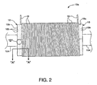
- the primary winding 10a comprises an electrical conductor 16 wound around the first winding leg 104 on a continuous basis (see Figure 2 ).
- the electrical conductor 16 can be, for example, rectangular, round, or flattened-round aluminum or copper wire.
- the primary winding 10a also comprises face-width sheet layer insulation. More particularly, the primary winding 10a comprises sheets of insulation 18 (see Figures 2-4 ).
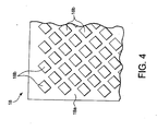
- the sheets of insulation 18 can be formed, for example, from heat-curable epoxy diamond pattern coated kraft paper (commonly referred to as "DPP paper").
- Each insulating sheet 18 comprises a base paper 18a (see Figure 4 ).
- Each insulating sheet 18 also comprises a plurality of relatively small diamond-shaped areas, or dots, of "B" stage epoxy adhesive 18b deposited on the base paper 18a as shown in Figure 4 .
- the adhesive 18b is located on both sides of the base paper 18a.
- the preferred method can also be practiced using insulating sheets having adhesive deposited on only one side of the base paper thereof. Moreover, the preferred method can be practiced using other types of insulation such as heat-curable epoxy fully coated kraft paper.
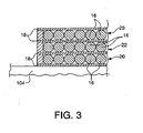
- the primary winding 10a comprises overlapping layers of turns of the electrical conductor 16. A respective one of the sheets of insulation 18 is positioned between each of the overlapping layers of turns (see Figure 3 ). The turns in each layer advance progressively across the width of the primary winding 10a.
- each overlapping layer of the primary winding 10a is formed by winding the electrical conductor 16 in a plurality of turns arranged in a side by side relationship across the width of the primary winding 10a.
- the primary winding 10a is formed by placing one of the sheets of insulation 18 on an outer surface of the first winding leg 104 so that the sheet of insulation 18 covers a portion of the outer surface.
- a first layer of turns 20 is subsequently wound onto the first winding leg 104. More particularly, the electrical conductor 16 is wound around the winding leg 104 and over the sheet of insulation 18, until a predetermined number of adjacent (side by side) turns have been formed.
- the winding operation can be performed manually, or using a conventional automated winding machine such as a model AM 3175 layer winding machine available from BR Technologies GmbH.
- the second layer of turns 22 is formed after the first layer of turns 20 has been formed in the above-described manner.
- another of the sheets of insulation 18 is placed over the first layer of turns 20 so that an edge of the sheet of insulation 18 extends across the first layer of turns 20 (see Figure 2 ).
- the sheet of insulation 18 can be cut so that opposing ends of the sheet of insulation 18 meet as shown in Figure 2 .
- the electrical conductor 16 is subsequently wound over the first layer of turns 20 and the overlying sheet of insulation 18 to form the second layer of turns 22, in the manner described above in relation to the first layer of turns 20 (see Figure 3 ).
- the second layer of turns 22 is formed by winding the electrical conductor 16 into a series of adjacent turns progressing back across the first layer of turns 20, until a predetermined turns count is reached.
- a continuous strip of insulating material can be used in lieu of the sheets of insulation 18.
- the continuous strip of insulating material can be continuously wound ahead of the electrical conductor 16 to provide substantially the same insulating properties as the sheets of insulation 18.
- the insulating strip can be positioned around a particular layer of the electrical conductor 16, and then cut to an appropriate length at the end of the layer using conventional techniques commonly known to those skilled in the art of transformer design and manufacture.
- the primary winding 10a can be wound on a mandrel and subsequently installed on the first winding leg 104, in lieu of winding the primary winding 10a directly onto the first winding leg 104.
- the secondary winding 11a can subsequently be wound on the first winding leg 104 in the manner described above in connection with the primary winding 10a.
- the number of turns of the electrical conductor 16 in each layer of the primary and secondary windings 10a, 11a differs.
- the primary and secondary windings 10a, 11a are otherwise substantially identical.
- the primary windings 10b, 10c and the secondary windings 11b, 11c can be wound in the above-described manner on a simultaneous or sequential basis with the primary and secondary winding 10a, 11a.
- the upper yoke 100 can be secured to the first, second, and third winding legs 104, 106, 108 after the primary windings 10a, 10b, 10c and the secondary windings 11a, 11b, 11c have been wound.
- the adhesive on the sheets of insulation 18 of the primary winding 10a can subsequently be melted and cured as follows.
- Opposing ends of the electrical conductor 16 of the primary winding 10a can be electrically coupled to a conventional DC power supply 120 (the DC power supply 120 and the primary winding 10a are depicted schematically in Figure 5 ).
- the DC power supply 120 should be capable of providing a DC current in the primary winding 10a greater the rated current of the primary winding 10a.
- the DC power supply 120 is electrically coupled to a variable power regulator 121 to facilitate control of the current supplied to the electrical conductor 16 by the DC power supply 120. (The variable power regulator 121 may or may not be part of the DC power supply 120.)
- variable power regulator 121 should be adjusted so that a DC current greater than the rated current of the primary winding 10a initially flows through the electrical conductor 16.
- the resistance of the electrical conductor 16 to the flow of current therethrough causes the temperature of the electrical conductor 16 to rise within each individual layer thereof.
- the layers of the electrical conductor 16 in turn, heat the adjacent sheets of insulation 18 (including the adhesive 18b).
- variable power regulator 121 is adjusted so that the DC current through the electrical conductor 16 is initially three times to five times the rated current of the primary winding 10a. Subjecting the electrical conductor 16 to a current of this magnitude is believed to be necessary to facilitate a relatively quick transition through the range of temperatures (approximately 60° C to approximately 100° C) at which the adhesive 18b begins to melt.
- the desired curing temperature of the adhesive 18b is approximately 130° C ⁇ approximately 15° C.
- the temperature of the primary winding 10a should be monitored, and the DC current through the primary winding 10a should be adjusted incrementally until the temperature of the primary winding 10a stabilizes within the desired range. More particularly, the DC current through the primary winding 10a should be maintained at its initial level until the temperature of the primary winding 10a is approximately equal to the target value of 130° C. The DC current can subsequently be decreased in increments of approximately 1° C until the temperature of the primary winding 10a stabilizes within the desired range.
- melting and curing temperatures for the adhesive 18b are application-dependent and supplier-dependent, and specific values for these parameters are included for exemplary purposes only.
- the temperature of the primary winding 10a should subsequently be monitored, and the variable power regulator 121 should be adjusted as necessary to maintain the temperature of the primary winding 10a within the range required to adequately cure the adhesive 18b.
- the resistance R d can be calculated by dividing the voltage across the electrical conductor 16 by the current therethrough.
- a conventional voltmeter 122 and a conventional ammeter 124 capable of providing the noted voltage and current measurements are depicted schematically in Figure 5 ).
- the initial temperature T o of the electrical conductor 16 can be estimated based on the ambient temperature, or by measurements obtained using a conventional temperature-measurement device such as an RTD.
- the initial resistance R o of the electrical conductor can be calculated by dividing the initial voltage across the electrical conductor 16 by the initial current therethrough.
- the predetermined period can be, for example, twenty to ninety minutes, depending on the size of the primary winding 10a.
- the flow of current though the electrical conductor 16 can be interrupted upon reaching the end of the predetermined period, and the electrical conductor 16 can be disconnected from the DC power supply 120 and the variable power regulator 121.
- the adhesive 18b can thus be melted and cured without placing the primary winding 10a in a hot-air convection oven. Hence, the time associated with transferring the primary winding 10a to and from the hot-air convection oven can be eliminated though the use of the preferred method.
- the cycle time required to melt and cure the adhesive 18b is substantially lower when using the preferred method in lieu of a hot-air convection oven.
- the electrical conductor 10 as a heat source, it is believed, heats the primary winding 10a more quickly, and in a more uniform manner than a hot-air convection oven.
- the temperature of the primary winding 10a can thus be stabilized at a desired value more quickly than is possible using a hot-air convection oven.
- substantial reductions the cycle time associated with the manufacture of the primary winding 10a can potentially be achieved through the use of the preferred method.
- the more uniform heating achieved using the electrical conductor 16 as a heat source can result in stronger mechanical bonds between the sheets of insulation 18 and the adjacent layers of the electrical conductor 16.
- the improved bonding can be particularly significant in the innermost layers of the primary winding 10, which can be difficult to heat using a hot-air convection oven.
- the energy required to heat the primary winding 10a by flowing electrical current through the electrical conductor 16 is substantially less than that required to heat the primary winding 10a using a hot-air convection oven. Hence, cost savings attributable to lower energy use can be potentially achieved through the use of the preferred method.
- the adhesive 18b in the primary windings 10b, 10c and the secondary windings 11a, 11b, 11c can subsequently be melted and cured in the manner described above in relation to the primary winding 10a.
- the primary windings 10a, 10b, 10c and the secondary windings 11a, 11b, 11c can be electrically coupled to the DC power supply 120 and the variable power regulator 121 in series, and the adhesive 18b in each of the primary windings 10a, 10b, 10c and the secondary windings 11a, 11b, 11c can be melted and cured on a substantially simultaneous basis.
- alternating current can be used in the alternative.
- Alternating current if used, should be of relatively low frequency, or should be used in combination with direct current to facilitate calculation of the temperature of the electrical conductor 16 in the above-described manner.
Landscapes
- Engineering & Computer Science (AREA)
- Power Engineering (AREA)
- Manufacturing & Machinery (AREA)
- Insulating Of Coils (AREA)
- Coils Of Transformers For General Uses (AREA)
Priority Applications (1)
| Application Number | Priority Date | Filing Date | Title |
|---|---|---|---|
| PL04777117T PL1639611T3 (pl) | 2003-06-27 | 2004-06-25 | Sposób wytwarzania uzwojenia transformatora |
Applications Claiming Priority (2)
| Application Number | Priority Date | Filing Date | Title |
|---|---|---|---|
| US10/608,353 US7398589B2 (en) | 2003-06-27 | 2003-06-27 | Method for manufacturing a transformer winding |
| PCT/US2004/020463 WO2005001854A2 (en) | 2003-06-27 | 2004-06-25 | Method for manufacturing a transformer winding |
Publications (3)
| Publication Number | Publication Date |
|---|---|
| EP1639611A2 EP1639611A2 (en) | 2006-03-29 |
| EP1639611A4 EP1639611A4 (en) | 2010-11-10 |
| EP1639611B1 true EP1639611B1 (en) | 2014-04-23 |
Family
ID=33540566
Family Applications (1)
| Application Number | Title | Priority Date | Filing Date |
|---|---|---|---|
| EP04777117.5A Expired - Lifetime EP1639611B1 (en) | 2003-06-27 | 2004-06-25 | Method for manufacturing a transformer winding |
Country Status (10)
| Country | Link |
|---|---|
| US (1) | US7398589B2 (pl) |
| EP (1) | EP1639611B1 (pl) |
| JP (1) | JP2007525009A (pl) |
| KR (1) | KR101123229B1 (pl) |
| CN (1) | CN100552836C (pl) |
| BR (1) | BRPI0411838B1 (pl) |
| CA (1) | CA2528582C (pl) |
| ES (1) | ES2478003T3 (pl) |
| PL (1) | PL1639611T3 (pl) |
| WO (1) | WO2005001854A2 (pl) |
Families Citing this family (17)
| Publication number | Priority date | Publication date | Assignee | Title |
|---|---|---|---|---|
| US7667441B2 (en) * | 2007-04-25 | 2010-02-23 | Texas Instruments Incorporated | Inductive element for a multi-phase interleaved power supply and apparatus and method using the same |
| DE102007053685A1 (de) * | 2007-11-10 | 2009-05-14 | Abb Technology Ag | Herstellungsverfahren für eine mehrlagige Transformatorwicklung mit Isolationsschicht |
| KR100927685B1 (ko) * | 2008-09-01 | 2009-11-20 | 제룡산업 주식회사 | 지중 매설형 고형 절연 변압기의 제조방법 |
| KR100920181B1 (ko) * | 2008-11-28 | 2009-10-06 | 주식회사 상용조명 | 다등용 안정기 및 그의 제조 방법 |
| JP5522658B2 (ja) * | 2009-10-08 | 2014-06-18 | トクデン株式会社 | 静止型誘導機器 |
| CN102545497A (zh) * | 2012-02-13 | 2012-07-04 | 浙江省金华市电机实业有限公司 | 一种定子散嵌绕组浸漆烘干方法 |
| JP5991467B2 (ja) * | 2012-06-08 | 2016-09-14 | Tdk株式会社 | コイル部品 |
| US9520224B2 (en) * | 2012-08-14 | 2016-12-13 | Siemens Energy, Inc. | Use of alumina paper for strain relief and electrical insulation in high-temperature coil windings |
| US10163562B2 (en) * | 2012-12-05 | 2018-12-25 | Futurewei Technologies, Inc. | Coupled inductor structure |
| KR101468821B1 (ko) * | 2012-12-19 | 2014-12-03 | 티디케이가부시기가이샤 | 커먼 모드 필터 |
| DE102013022430B4 (de) | 2012-12-19 | 2025-02-06 | Tdk Corporation | Gleichtaktfilter |
| US9640315B2 (en) * | 2013-05-13 | 2017-05-02 | General Electric Company | Low stray-loss transformers and methods of assembling the same |
| CN103471738A (zh) * | 2013-09-25 | 2013-12-25 | 哈尔滨工业大学 | 等离子体霍尔效应推力器励磁绕组温度在线监测方法 |
| JP6149750B2 (ja) * | 2014-02-07 | 2017-06-21 | トヨタ自動車株式会社 | リアクトルの固定方法 |
| US10872843B2 (en) | 2017-05-02 | 2020-12-22 | Micron Technology, Inc. | Semiconductor devices with back-side coils for wireless signal and power coupling |
| US20180323369A1 (en) * | 2017-05-02 | 2018-11-08 | Micron Technology, Inc. | Inductors with through-substrate via cores |
| KR102100495B1 (ko) | 2020-01-29 | 2020-05-26 | 제룡전기 주식회사 | 친환경 하이브리드 에폭시 수지 조성물을 적용한 몰드 변압기 권선의 구조 및 이의 제조방법 |
Family Cites Families (42)
| Publication number | Priority date | Publication date | Assignee | Title |
|---|---|---|---|---|
| US3200357A (en) * | 1962-08-23 | 1965-08-10 | Porter Co Inc H K | Transformer coil construction |
| US3675174A (en) * | 1970-11-09 | 1972-07-04 | Electronic Associates | Electrical coil and method of manufacturing same |
| US3774298A (en) * | 1972-06-29 | 1973-11-27 | Westinghouse Electric Corp | Method of constructing a transformer winding assembly |
| US3904785A (en) * | 1974-01-11 | 1975-09-09 | Gen Electric | Method for insulating electric armature windings |
| US4051809A (en) * | 1976-09-22 | 1977-10-04 | Westinghouse Electric Corporation | Apparatus for cleaning and coating an elongated metallic member |
| US4204087A (en) * | 1976-11-22 | 1980-05-20 | Westinghouse Electric Corp. | Adhesive coated electrical conductors |
| US4521956A (en) | 1983-07-11 | 1985-06-11 | General Electric Company | Method for making a transformer having improved space factor |
| US4554730A (en) * | 1984-01-09 | 1985-11-26 | Westinghouse Electric Corp. | Method of making a void-free non-cellulose electrical winding |
| US4741947A (en) * | 1986-04-24 | 1988-05-03 | Westinghouse Electric Corp. | Water-based epoxy patterned porous insulation |
| US4741974A (en) * | 1986-05-20 | 1988-05-03 | The Perkin-Elmer Corporation | Composite wire for wear resistant coatings |
| JPH0735372Y2 (ja) * | 1987-04-24 | 1995-08-09 | 日新電機株式会社 | ガス絶縁電圧変成器 |
| US5194181A (en) * | 1988-07-15 | 1993-03-16 | The United States Of America As Represented By The Secretary Of The Navy | Process for shaping articles from electrosetting compositions |
| JPH03129808A (ja) * | 1989-10-16 | 1991-06-03 | Toshiba Corp | 電気機器用モールドコイルの硬化方法及びその硬化装置 |
| JPH04119609A (ja) * | 1990-09-10 | 1992-04-21 | Toshiba Corp | モールドコイルの製造方法 |
| US5357015A (en) * | 1991-05-29 | 1994-10-18 | Board Of Regents, The University Of Texas | Electric field curing of polymers |
| US5474799A (en) * | 1992-10-13 | 1995-12-12 | Reliance Electric Industrial Company | Apparatus and method for coating an electromagnetic coil |
| US5589129A (en) * | 1993-02-19 | 1996-12-31 | Kabushiki Kaisha Toshiba | Method of manufacturing a molding using a filler or an additive concentrated on an arbitrary portion or distributed at a gradient concentration |
| US5461772A (en) * | 1993-03-17 | 1995-10-31 | Square D Company | Method of manufacturing a strip wound coil to reinforce edge layer insulation |
| US5367760A (en) * | 1993-04-26 | 1994-11-29 | Terlop; William E. | Method of making a narrow profile transformer |
| JPH07326525A (ja) * | 1994-05-31 | 1995-12-12 | Sumitomo 3M Ltd | 絶縁性粘着テープ及びそれを用いたトランス |
| US5648137A (en) * | 1994-08-08 | 1997-07-15 | Blackmore; Richard | Advanced cured resin composite parts and method of forming such parts |
| US5861791A (en) * | 1995-06-21 | 1999-01-19 | Brunswick Corporation | Ignition coil with non-filtering/non-segregating secondary winding separators |
| JP3741817B2 (ja) * | 1996-06-03 | 2006-02-01 | 財団法人鉄道総合技術研究所 | 反応射出成形方法 |
| ES2281085T3 (es) * | 1996-09-04 | 2007-09-16 | Schneider Electric Industries Sas | Bobinaje de alta tension de tipo seco. |
| US5710535A (en) * | 1996-12-06 | 1998-01-20 | Caterpillar Inc. | Coil assembly for a solenoid valve |
| SE510925C2 (sv) * | 1997-11-26 | 1999-07-12 | Asea Brown Boveri | Elektromagnetisk anordning |
| JPH11176660A (ja) * | 1997-12-08 | 1999-07-02 | Sanken Electric Co Ltd | コイルを含む電気回路装置 |
| JPH11224821A (ja) * | 1998-02-05 | 1999-08-17 | Matsushita Electric Ind Co Ltd | 電磁コイル |
| US6160464A (en) * | 1998-02-06 | 2000-12-12 | Dynapower Corporation | Solid cast resin coil for high voltage transformer, high voltage transformer using same, and method of producing same |
| JP3613994B2 (ja) * | 1998-02-12 | 2005-01-26 | トヨタ自動車株式会社 | 平角線コイル製造装置および平角線コイル製造方法 |
| US6411188B1 (en) * | 1998-03-27 | 2002-06-25 | Honeywell International Inc. | Amorphous metal transformer having a generally rectangular coil |
| JP4093435B2 (ja) * | 1998-09-07 | 2008-06-04 | 日本板硝子株式会社 | 光モジュールの製造方法 |
| US6359062B1 (en) * | 1999-03-02 | 2002-03-19 | The Valspar Corporation | Coating compositions |
| US6248279B1 (en) * | 1999-05-25 | 2001-06-19 | Panzer Tool Works, Inc. | Method and apparatus for encapsulating a ring-shaped member |
| US6256865B1 (en) * | 1999-06-07 | 2001-07-10 | General Electric Company | Continuous winding process and apparatus for electrical transformers |
| US6223421B1 (en) * | 1999-09-27 | 2001-05-01 | Abb Power T&D Company Inc. | Method of manufacturing a transformer coil with a disposable mandrel and mold |
| US6221297B1 (en) * | 1999-09-27 | 2001-04-24 | Abb Power T&D Company Inc. | Method of manufacturing a transformer coil with a disposable wrap and band mold and integrated winding mandrel |
| US6368530B1 (en) * | 1999-12-16 | 2002-04-09 | Square D Company | Method of forming cooling ducts in cast resin coils |
| DE10132718A1 (de) * | 2001-07-05 | 2003-02-13 | Abb T & D Tech Ltd | Verfahren zum Bewickeln eines Dreiphasen-Kabeltransformators mit Koaxialkabel und Wickelvorrichtung hierzu |
| US6624734B2 (en) * | 2001-09-21 | 2003-09-23 | Abb Technology Ag | DC voltage/current heating/gelling/curing of resin encapsulated distribution transformer coils |
| US20040003492A1 (en) * | 2002-07-02 | 2004-01-08 | Chi-Chih Wu | Method for winding transformers |
| US7260883B2 (en) * | 2003-06-19 | 2007-08-28 | Abb Technology Ag | Method for forming a winding for a three-phase transformer |
-
2003
- 2003-06-27 US US10/608,353 patent/US7398589B2/en not_active Expired - Lifetime
-
2004
- 2004-06-25 JP JP2006517676A patent/JP2007525009A/ja active Pending
- 2004-06-25 BR BRPI0411838A patent/BRPI0411838B1/pt not_active IP Right Cessation
- 2004-06-25 CA CA2528582A patent/CA2528582C/en not_active Expired - Fee Related
- 2004-06-25 ES ES04777117.5T patent/ES2478003T3/es not_active Expired - Lifetime
- 2004-06-25 PL PL04777117T patent/PL1639611T3/pl unknown
- 2004-06-25 EP EP04777117.5A patent/EP1639611B1/en not_active Expired - Lifetime
- 2004-06-25 WO PCT/US2004/020463 patent/WO2005001854A2/en not_active Ceased
- 2004-06-25 KR KR1020057024590A patent/KR101123229B1/ko not_active Expired - Fee Related
- 2004-06-25 CN CNB2004800181463A patent/CN100552836C/zh not_active Expired - Fee Related
Also Published As
| Publication number | Publication date |
|---|---|
| JP2007525009A (ja) | 2007-08-30 |
| EP1639611A2 (en) | 2006-03-29 |
| KR20060015657A (ko) | 2006-02-17 |
| WO2005001854A3 (en) | 2005-09-15 |
| ES2478003T3 (es) | 2014-07-18 |
| CN1813321A (zh) | 2006-08-02 |
| BRPI0411838A2 (pt) | 2019-04-24 |
| EP1639611A4 (en) | 2010-11-10 |
| CN100552836C (zh) | 2009-10-21 |
| WO2005001854A2 (en) | 2005-01-06 |
| CA2528582C (en) | 2012-12-04 |
| US20040261252A1 (en) | 2004-12-30 |
| CA2528582A1 (en) | 2005-01-06 |
| KR101123229B1 (ko) | 2012-03-20 |
| BRPI0411838B1 (pt) | 2019-12-31 |
| US7398589B2 (en) | 2008-07-15 |
| PL1639611T3 (pl) | 2014-11-28 |
Similar Documents
| Publication | Publication Date | Title |
|---|---|---|
| EP1639611B1 (en) | Method for manufacturing a transformer winding | |
| US11075032B2 (en) | Power transformers and methods of manufacturing transformers and windings | |
| AU768932B2 (en) | Method for producing a magnetically excitable core comprising a core winding for an electric machine | |
| US4376904A (en) | Insulated electromagnetic coil | |
| US4355221A (en) | Method of field annealing an amorphous metal core by means of induction heating | |
| RU2237306C2 (ru) | Трехфазный трансформатор | |
| US7260883B2 (en) | Method for forming a winding for a three-phase transformer | |
| US10058950B1 (en) | Systems and methods for use in induction welding | |
| EP0310813A1 (en) | Butt-lap-step core joint | |
| US6663039B2 (en) | Process for manufacturing an electrical-power transformer having phase windings formed from insulated conductive cabling | |
| JP2000215972A (ja) | 誘導加熱コイルおよびその製造方法 | |
| US20150364239A1 (en) | Forming amorphous metal transformer cores | |
| US20150380148A1 (en) | Methods and systems for forming amorphous metal transformer cores | |
| TWI328511B (en) | Magnetic implement using magnetic metal ribbon coated with insulator | |
| CA2096725C (en) | Dual surface heaters | |
| JP2007330093A (ja) | 粉末被覆された発電機回転子コイルを硬化するためのジュール加熱装置 | |
| Das et al. | Optimal design and experimental validation of a novel line-frequency zig-zag transformer employed in a unified ac-dc system | |
| US20050034296A1 (en) | Method of forming a transformer winding with rectangular copper wire | |
| Vologdin et al. | Simulation of induction system for brazing of squirrel cage rotor | |
| Cook et al. | Transformer design and load matching | |
| Wilson et al. | Bondable insulation systems | |
| JPS6237514B2 (pl) | ||
| US20170345544A1 (en) | Methods and systems for forming amorphous metal transformer cores | |
| JPS61179519A (ja) | 鉄心の製造方法 |
Legal Events
| Date | Code | Title | Description |
|---|---|---|---|
| PUAI | Public reference made under article 153(3) epc to a published international application that has entered the european phase |
Free format text: ORIGINAL CODE: 0009012 |
|
| 17P | Request for examination filed |
Effective date: 20051213 |
|
| AK | Designated contracting states |
Kind code of ref document: A2 Designated state(s): AT BE BG CH CY CZ DE DK EE ES FI FR GB GR HU IE IT LI LU MC NL PL PT RO SE SI SK TR |
|
| AX | Request for extension of the european patent |
Extension state: AL HR LT LV MK |
|
| DAX | Request for extension of the european patent (deleted) | ||
| A4 | Supplementary search report drawn up and despatched |
Effective date: 20101007 |
|
| 17Q | First examination report despatched |
Effective date: 20110125 |
|
| REG | Reference to a national code |
Ref country code: DE Ref legal event code: R079 Ref document number: 602004044910 Country of ref document: DE Free format text: PREVIOUS MAIN CLASS: H01F0007060000 Ipc: H01F0041120000 |
|
| RIC1 | Information provided on ipc code assigned before grant |
Ipc: H01F 27/32 20060101ALI20130906BHEP Ipc: H01F 41/12 20060101AFI20130906BHEP |
|
| GRAP | Despatch of communication of intention to grant a patent |
Free format text: ORIGINAL CODE: EPIDOSNIGR1 |
|
| INTG | Intention to grant announced |
Effective date: 20131114 |
|
| GRAS | Grant fee paid |
Free format text: ORIGINAL CODE: EPIDOSNIGR3 |
|
| GRAA | (expected) grant |
Free format text: ORIGINAL CODE: 0009210 |
|
| AK | Designated contracting states |
Kind code of ref document: B1 Designated state(s): AT BE BG CH CY CZ DE DK EE ES FI FR GB GR HU IE IT LI LU MC NL PL PT RO SE SI SK TR |
|
| REG | Reference to a national code |
Ref country code: GB Ref legal event code: FG4D Ref country code: DE Ref legal event code: R081 Ref document number: 602004044910 Country of ref document: DE Owner name: ABB SCHWEIZ AG, CH Free format text: FORMER OWNER: ABB TECHNOLOGY AG, ZUERICH, CH |
|
| REG | Reference to a national code |
Ref country code: CH Ref legal event code: EP |
|
| REG | Reference to a national code |
Ref country code: AT Ref legal event code: REF Ref document number: 664255 Country of ref document: AT Kind code of ref document: T Effective date: 20140515 |
|
| REG | Reference to a national code |
Ref country code: IE Ref legal event code: FG4D |
|
| REG | Reference to a national code |
Ref country code: DE Ref legal event code: R096 Ref document number: 602004044910 Country of ref document: DE Effective date: 20140528 |
|
| REG | Reference to a national code |
Ref country code: ES Ref legal event code: FG2A Ref document number: 2478003 Country of ref document: ES Kind code of ref document: T3 Effective date: 20140718 |
|
| REG | Reference to a national code |
Ref country code: AT Ref legal event code: MK05 Ref document number: 664255 Country of ref document: AT Kind code of ref document: T Effective date: 20140423 |
|
| REG | Reference to a national code |
Ref country code: NL Ref legal event code: VDEP Effective date: 20140423 |
|
| PG25 | Lapsed in a contracting state [announced via postgrant information from national office to epo] |
Ref country code: BG Free format text: LAPSE BECAUSE OF FAILURE TO SUBMIT A TRANSLATION OF THE DESCRIPTION OR TO PAY THE FEE WITHIN THE PRESCRIBED TIME-LIMIT Effective date: 20140723 Ref country code: NL Free format text: LAPSE BECAUSE OF FAILURE TO SUBMIT A TRANSLATION OF THE DESCRIPTION OR TO PAY THE FEE WITHIN THE PRESCRIBED TIME-LIMIT Effective date: 20140423 Ref country code: CY Free format text: LAPSE BECAUSE OF FAILURE TO SUBMIT A TRANSLATION OF THE DESCRIPTION OR TO PAY THE FEE WITHIN THE PRESCRIBED TIME-LIMIT Effective date: 20140423 Ref country code: GR Free format text: LAPSE BECAUSE OF FAILURE TO SUBMIT A TRANSLATION OF THE DESCRIPTION OR TO PAY THE FEE WITHIN THE PRESCRIBED TIME-LIMIT Effective date: 20140724 |
|
| PG25 | Lapsed in a contracting state [announced via postgrant information from national office to epo] |
Ref country code: SE Free format text: LAPSE BECAUSE OF FAILURE TO SUBMIT A TRANSLATION OF THE DESCRIPTION OR TO PAY THE FEE WITHIN THE PRESCRIBED TIME-LIMIT Effective date: 20140423 Ref country code: AT Free format text: LAPSE BECAUSE OF FAILURE TO SUBMIT A TRANSLATION OF THE DESCRIPTION OR TO PAY THE FEE WITHIN THE PRESCRIBED TIME-LIMIT Effective date: 20140423 |
|
| REG | Reference to a national code |
Ref country code: PL Ref legal event code: T3 |
|
| PG25 | Lapsed in a contracting state [announced via postgrant information from national office to epo] |
Ref country code: PT Free format text: LAPSE BECAUSE OF FAILURE TO SUBMIT A TRANSLATION OF THE DESCRIPTION OR TO PAY THE FEE WITHIN THE PRESCRIBED TIME-LIMIT Effective date: 20140825 |
|
| REG | Reference to a national code |
Ref country code: DE Ref legal event code: R097 Ref document number: 602004044910 Country of ref document: DE |
|
| PG25 | Lapsed in a contracting state [announced via postgrant information from national office to epo] |
Ref country code: RO Free format text: LAPSE BECAUSE OF FAILURE TO SUBMIT A TRANSLATION OF THE DESCRIPTION OR TO PAY THE FEE WITHIN THE PRESCRIBED TIME-LIMIT Effective date: 20140423 Ref country code: MC Free format text: LAPSE BECAUSE OF FAILURE TO SUBMIT A TRANSLATION OF THE DESCRIPTION OR TO PAY THE FEE WITHIN THE PRESCRIBED TIME-LIMIT Effective date: 20140423 Ref country code: BE Free format text: LAPSE BECAUSE OF FAILURE TO SUBMIT A TRANSLATION OF THE DESCRIPTION OR TO PAY THE FEE WITHIN THE PRESCRIBED TIME-LIMIT Effective date: 20140423 Ref country code: LU Free format text: LAPSE BECAUSE OF FAILURE TO SUBMIT A TRANSLATION OF THE DESCRIPTION OR TO PAY THE FEE WITHIN THE PRESCRIBED TIME-LIMIT Effective date: 20140625 Ref country code: CZ Free format text: LAPSE BECAUSE OF FAILURE TO SUBMIT A TRANSLATION OF THE DESCRIPTION OR TO PAY THE FEE WITHIN THE PRESCRIBED TIME-LIMIT Effective date: 20140423 Ref country code: EE Free format text: LAPSE BECAUSE OF FAILURE TO SUBMIT A TRANSLATION OF THE DESCRIPTION OR TO PAY THE FEE WITHIN THE PRESCRIBED TIME-LIMIT Effective date: 20140423 Ref country code: DK Free format text: LAPSE BECAUSE OF FAILURE TO SUBMIT A TRANSLATION OF THE DESCRIPTION OR TO PAY THE FEE WITHIN THE PRESCRIBED TIME-LIMIT Effective date: 20140423 Ref country code: SK Free format text: LAPSE BECAUSE OF FAILURE TO SUBMIT A TRANSLATION OF THE DESCRIPTION OR TO PAY THE FEE WITHIN THE PRESCRIBED TIME-LIMIT Effective date: 20140423 |
|
| REG | Reference to a national code |
Ref country code: CH Ref legal event code: PL |
|
| PLBE | No opposition filed within time limit |
Free format text: ORIGINAL CODE: 0009261 |
|
| STAA | Information on the status of an ep patent application or granted ep patent |
Free format text: STATUS: NO OPPOSITION FILED WITHIN TIME LIMIT |
|
| GBPC | Gb: european patent ceased through non-payment of renewal fee |
Effective date: 20140723 |
|
| REG | Reference to a national code |
Ref country code: IE Ref legal event code: MM4A |
|
| PG25 | Lapsed in a contracting state [announced via postgrant information from national office to epo] |
Ref country code: IT Free format text: LAPSE BECAUSE OF FAILURE TO SUBMIT A TRANSLATION OF THE DESCRIPTION OR TO PAY THE FEE WITHIN THE PRESCRIBED TIME-LIMIT Effective date: 20140423 |
|
| 26N | No opposition filed |
Effective date: 20150126 |
|
| PG25 | Lapsed in a contracting state [announced via postgrant information from national office to epo] |
Ref country code: CH Free format text: LAPSE BECAUSE OF NON-PAYMENT OF DUE FEES Effective date: 20140630 Ref country code: IE Free format text: LAPSE BECAUSE OF NON-PAYMENT OF DUE FEES Effective date: 20140625 Ref country code: LI Free format text: LAPSE BECAUSE OF NON-PAYMENT OF DUE FEES Effective date: 20140630 |
|
| REG | Reference to a national code |
Ref country code: DE Ref legal event code: R097 Ref document number: 602004044910 Country of ref document: DE Effective date: 20150126 |
|
| PG25 | Lapsed in a contracting state [announced via postgrant information from national office to epo] |
Ref country code: GB Free format text: LAPSE BECAUSE OF NON-PAYMENT OF DUE FEES Effective date: 20140723 |
|
| PG25 | Lapsed in a contracting state [announced via postgrant information from national office to epo] |
Ref country code: SI Free format text: LAPSE BECAUSE OF FAILURE TO SUBMIT A TRANSLATION OF THE DESCRIPTION OR TO PAY THE FEE WITHIN THE PRESCRIBED TIME-LIMIT Effective date: 20140423 |
|
| REG | Reference to a national code |
Ref country code: FR Ref legal event code: PLFP Year of fee payment: 13 |
|
| PG25 | Lapsed in a contracting state [announced via postgrant information from national office to epo] |
Ref country code: HU Free format text: LAPSE BECAUSE OF FAILURE TO SUBMIT A TRANSLATION OF THE DESCRIPTION OR TO PAY THE FEE WITHIN THE PRESCRIBED TIME-LIMIT; INVALID AB INITIO Effective date: 20040625 |
|
| REG | Reference to a national code |
Ref country code: DE Ref legal event code: R081 Ref document number: 602004044910 Country of ref document: DE Owner name: ABB SCHWEIZ AG, CH Free format text: FORMER OWNER: ABB TECHNOLOGY AG, ZUERICH, CH Ref country code: DE Ref legal event code: R081 Ref document number: 602004044910 Country of ref document: DE Owner name: ABB POWER GRIDS SWITZERLAND AG, CH Free format text: FORMER OWNER: ABB TECHNOLOGY AG, ZUERICH, CH Ref country code: DE Ref legal event code: R082 Ref document number: 602004044910 Country of ref document: DE Representative=s name: DENNEMEYER & ASSOCIATES S.A., DE Ref country code: DE Ref legal event code: R082 Ref document number: 602004044910 Country of ref document: DE Representative=s name: KUHNEN & WACKER PATENT- UND RECHTSANWALTSBUERO, DE |
|
| REG | Reference to a national code |
Ref country code: FR Ref legal event code: PLFP Year of fee payment: 14 |
|
| REG | Reference to a national code |
Ref country code: ES Ref legal event code: PC2A Owner name: ABB SCHWEIZ AG Effective date: 20171213 |
|
| REG | Reference to a national code |
Ref country code: FR Ref legal event code: PLFP Year of fee payment: 15 |
|
| REG | Reference to a national code |
Ref country code: FR Ref legal event code: TP Owner name: ABB SCHWEIZ AG, CH Effective date: 20180912 |
|
| REG | Reference to a national code |
Ref country code: FI Ref legal event code: PCE Owner name: ABB POWER GRIDS SWITZERLAND AG |
|
| REG | Reference to a national code |
Ref country code: DE Ref legal event code: R082 Ref document number: 602004044910 Country of ref document: DE Representative=s name: DENNEMEYER & ASSOCIATES S.A., DE Ref country code: DE Ref legal event code: R081 Ref document number: 602004044910 Country of ref document: DE Owner name: ABB POWER GRIDS SWITZERLAND AG, CH Free format text: FORMER OWNER: ABB SCHWEIZ AG, BADEN, CH |
|
| REG | Reference to a national code |
Ref country code: ES Ref legal event code: PC2A Owner name: ABB POWER GRIDS SWITZERLAND AG Effective date: 20210525 |
|
| PGFP | Annual fee paid to national office [announced via postgrant information from national office to epo] |
Ref country code: FR Payment date: 20210622 Year of fee payment: 18 Ref country code: FI Payment date: 20210621 Year of fee payment: 18 Ref country code: DE Payment date: 20210618 Year of fee payment: 18 |
|
| PGFP | Annual fee paid to national office [announced via postgrant information from national office to epo] |
Ref country code: TR Payment date: 20210623 Year of fee payment: 18 Ref country code: PL Payment date: 20210617 Year of fee payment: 18 |
|
| PGFP | Annual fee paid to national office [announced via postgrant information from national office to epo] |
Ref country code: ES Payment date: 20210825 Year of fee payment: 18 |
|
| REG | Reference to a national code |
Ref country code: FI Ref legal event code: PCE Owner name: HITACHI ENERGY SWITZERLAND AG |
|
| REG | Reference to a national code |
Ref country code: ES Ref legal event code: PC2A Owner name: HITACHI ENERGY SWITZERLAND AG Effective date: 20220526 |
|
| REG | Reference to a national code |
Ref country code: DE Ref legal event code: R119 Ref document number: 602004044910 Country of ref document: DE |
|
| REG | Reference to a national code |
Ref country code: FI Ref legal event code: MAE |
|
| PG25 | Lapsed in a contracting state [announced via postgrant information from national office to epo] |
Ref country code: FI Free format text: LAPSE BECAUSE OF NON-PAYMENT OF DUE FEES Effective date: 20220625 |
|
| PG25 | Lapsed in a contracting state [announced via postgrant information from national office to epo] |
Ref country code: FR Free format text: LAPSE BECAUSE OF NON-PAYMENT OF DUE FEES Effective date: 20220630 |
|
| PG25 | Lapsed in a contracting state [announced via postgrant information from national office to epo] |
Ref country code: DE Free format text: LAPSE BECAUSE OF NON-PAYMENT OF DUE FEES Effective date: 20230103 |
|
| REG | Reference to a national code |
Ref country code: ES Ref legal event code: FD2A Effective date: 20230801 |
|
| PG25 | Lapsed in a contracting state [announced via postgrant information from national office to epo] |
Ref country code: PL Free format text: LAPSE BECAUSE OF NON-PAYMENT OF DUE FEES Effective date: 20220625 |
|
| PG25 | Lapsed in a contracting state [announced via postgrant information from national office to epo] |
Ref country code: ES Free format text: LAPSE BECAUSE OF NON-PAYMENT OF DUE FEES Effective date: 20220626 |
|
| PG25 | Lapsed in a contracting state [announced via postgrant information from national office to epo] |
Ref country code: TR Free format text: LAPSE BECAUSE OF NON-PAYMENT OF DUE FEES Effective date: 20220625 |