EP1637793A1 - Hydraulischer Aktuator mit Schwingungsdämpfer - Google Patents
Hydraulischer Aktuator mit Schwingungsdämpfer Download PDFInfo
- Publication number
- EP1637793A1 EP1637793A1 EP05020335A EP05020335A EP1637793A1 EP 1637793 A1 EP1637793 A1 EP 1637793A1 EP 05020335 A EP05020335 A EP 05020335A EP 05020335 A EP05020335 A EP 05020335A EP 1637793 A1 EP1637793 A1 EP 1637793A1
- Authority
- EP
- European Patent Office
- Prior art keywords
- master cylinder
- membrane
- vibration damping
- closure cap
- bore
- Prior art date
- Legal status (The legal status is an assumption and is not a legal conclusion. Google has not performed a legal analysis and makes no representation as to the accuracy of the status listed.)
- Granted
Links
- 239000006096 absorbing agent Substances 0.000 title 1
- 239000012528 membrane Substances 0.000 claims abstract description 18
- 239000012530 fluid Substances 0.000 claims abstract description 14
- 238000013016 damping Methods 0.000 claims description 33
- 238000013022 venting Methods 0.000 claims description 3
- 210000004379 membrane Anatomy 0.000 description 11
- 239000007788 liquid Substances 0.000 description 5
- 230000005540 biological transmission Effects 0.000 description 1
- 230000000881 depressing effect Effects 0.000 description 1
- 230000010355 oscillation Effects 0.000 description 1
Images
Classifications
-
- F—MECHANICAL ENGINEERING; LIGHTING; HEATING; WEAPONS; BLASTING
- F16—ENGINEERING ELEMENTS AND UNITS; GENERAL MEASURES FOR PRODUCING AND MAINTAINING EFFECTIVE FUNCTIONING OF MACHINES OR INSTALLATIONS; THERMAL INSULATION IN GENERAL
- F16L—PIPES; JOINTS OR FITTINGS FOR PIPES; SUPPORTS FOR PIPES, CABLES OR PROTECTIVE TUBING; MEANS FOR THERMAL INSULATION IN GENERAL
- F16L55/00—Devices or appurtenances for use in, or in connection with, pipes or pipe systems
- F16L55/04—Devices damping pulsations or vibrations in fluids
- F16L55/041—Devices damping pulsations or vibrations in fluids specially adapted for preventing vibrations
-
- F—MECHANICAL ENGINEERING; LIGHTING; HEATING; WEAPONS; BLASTING
- F16—ENGINEERING ELEMENTS AND UNITS; GENERAL MEASURES FOR PRODUCING AND MAINTAINING EFFECTIVE FUNCTIONING OF MACHINES OR INSTALLATIONS; THERMAL INSULATION IN GENERAL
- F16D—COUPLINGS FOR TRANSMITTING ROTATION; CLUTCHES; BRAKES
- F16D25/00—Fluid-actuated clutches
- F16D25/12—Details not specific to one of the before-mentioned types
-
- F—MECHANICAL ENGINEERING; LIGHTING; HEATING; WEAPONS; BLASTING
- F16—ENGINEERING ELEMENTS AND UNITS; GENERAL MEASURES FOR PRODUCING AND MAINTAINING EFFECTIVE FUNCTIONING OF MACHINES OR INSTALLATIONS; THERMAL INSULATION IN GENERAL
- F16D—COUPLINGS FOR TRANSMITTING ROTATION; CLUTCHES; BRAKES
- F16D48/00—External control of clutches
- F16D48/02—Control by fluid pressure
-
- F—MECHANICAL ENGINEERING; LIGHTING; HEATING; WEAPONS; BLASTING
- F16—ENGINEERING ELEMENTS AND UNITS; GENERAL MEASURES FOR PRODUCING AND MAINTAINING EFFECTIVE FUNCTIONING OF MACHINES OR INSTALLATIONS; THERMAL INSULATION IN GENERAL
- F16D—COUPLINGS FOR TRANSMITTING ROTATION; CLUTCHES; BRAKES
- F16D48/00—External control of clutches
- F16D48/02—Control by fluid pressure
- F16D2048/0215—Control by fluid pressure for damping of pulsations within the fluid system
Definitions
- the invention relates to hydraulic actuators, and more particularly, but not exclusively, to hydraulic actuators used as master or slave cylinders in a hydraulic system for actuating a vehicle clutch.
- One of the problems with such systems is to dampen vibrations generated by the associated clutch and vehicle drive in the pressurized fluid of the system to prevent the transmission of unpleasant noises or mechanical vibrations via the clutch pedal to the vehicle operator ,
- the object of the present invention is to provide an improved arrangement for incorporating such vibration dampers in a hydraulic system that is particularly suitable for use in a clutch actuation system.
- a master cylinder which has a cylinder body in which a working piston can slide in a bore, and before the piston defines a pressure chamber in which a working fluid is pressurized, wherein in the master cylinder body a two-stage vibration damper is housed consisting of a chamber of variable volume, which is connected for damping the vibrations in the working fluid via a throttle means with the pressure chamber.
- a second damping stage is achieved by the movement of the working fluid through the throttle element, and a second damping step by the expansion of the variable volume chamber.
- variable volume chamber is within the bore.
- variable volume chamber may be formed, for example, by a flexible diaphragm which is placed in a cavity formed between two parts of a vibration damping body located in the bore, between the outer surface of the membrane and the cavity, in which the membrane can dodge, for damping the vibrations in the working fluid one or more air cushion are.
- the damping cavity receiving the diaphragm may be conveniently provided between a main vibration damping body and a surrounding closure cap surrounding the diaphragm and secured to the main vibration damping body.
- the diaphragm may be fixedly installed between the main vibration damping body and the closure cap, the diaphragm having an annular flange surrounding an open end of the diaphragm and enclosed between opposing annular edges of the closure cap and the main vibration damping body.
- a portion of the main vibration damping body may protrude through the open end of the diaphragm and include a plurality of holes / grooves for venting the master cylinder, so that no air is trapped between the protruding part of the damping body and the inside of the surrounding diaphragm.
- the outside of the anti-vibration cap may also be provided with slots so that no air can be trapped between the cap and the bore in which the cap is enclosed.
- a master cylinder 10 has a base body 11 with a bore 12 in which a piston 13 can slide back and forth under the action of a piston rod 14 which is connected to a corresponding (not shown) clutch pedal.
- the main body 11 has an inlet port 15 which is connected to a (not shown) liquid container, and an outlet opening 16 which is connected via a (not shown) line with a clutch slave cylinder.
- Fig. 1 is located from the piston 13 seen on the left side of a pressure chamber 17, from which by a working movement of the piston 13, a pressurized liquid after the left side shown in Fig. 1 is displaced.
- a two-stage fluid vibration damper 18 is housed in the bore 12 at the left end.
- the vibration damper 18 comprises a generally cylindrical main vibration damping body 19 which is sealed to the bore 12 by an O-ring (or other suitable seal), and a through-bore 21, further comprising an annular slender portion 22 and a radial bore 23 which defines the slender Part 22 connects to the through hole 21.
- the slender part 22 is aligned with the outlet opening 16 so that the liquid is displaced from the pressure chamber 17 via the through-hole 21, the radial bore 23 and the slender part 22 to the outlet opening 16.
- a closure cap 24 is attached, which encloses a hat-shaped flexible membrane 25.
- the membrane 25 has an annular flange portion 26 which surrounds an opening 27 in the membrane 25 and is firmly enclosed between the opposing annular edges 28 and 29 of the main vibration damping body 19 and the closure cap 24, respectively.
- the closure cap 24 is provided with an internal groove 30 which forms an air cushion around the membrane 25. Between the closure cap 24 and the base part 33 of the membrane 25 there is another air cushion 32.
- the grooves 36 are interconnected by axial slots 36a. These ribs, grooves, slots and holes prevent air from being trapped between the end portion 34 of the main vibration damping body and the inner surface of the surrounding diaphragm 25. This is particularly important when venting the hydraulic system for the first time to remove trapped air.
- the outer surface of the closure cap 24 is also provided with a series of slots 38 and grooves 39 which prevent air from being trapped between the closure cap 24 and the surrounding bore 12. In this way, the entire outer surface of the closure cap 24 is surrounded by pressurized liquid, so that the total voltage acting on the closure cap 24 is reduced.
- the cap 24 and the main vibration damping body 19 are pressed against the end of the bore 12 by a piston return spring 13a acting between the piston 13 and the main vibration damping body 19.
- the above-described vibration damper 18 operates as follows.
- the master cylinder 10 is operated by depressing the clutch pedal, which moves the piston rod 14 to the left in the manner described above.
- the piston 13 is displaced to the left, wherein the pressurized fluid is displaced via the through hole 21, the radial bore 23 and the slender part 22 to the outlet opening 16 out.
- the vibrations transmitted to the working fluid of the system for example from the associated slave cylinder associated with the outlet port 16, reach the slender portion 22 of the main vibration damping body 19.
Landscapes
- Engineering & Computer Science (AREA)
- General Engineering & Computer Science (AREA)
- Mechanical Engineering (AREA)
- Physics & Mathematics (AREA)
- Fluid Mechanics (AREA)
- Hydraulic Clutches, Magnetic Clutches, Fluid Clutches, And Fluid Joints (AREA)
- Valve Device For Special Equipments (AREA)
- Fluid-Pressure Circuits (AREA)
- Lubricants (AREA)
Abstract
Description
- Die Erfindung betrifft hydraulische Aktuatoren und insbesondere, aber nicht ausschließlich, hydraulische Aktuatoren, die als Geber- oder Nehmerzylinder in einem Hydrauliksystem zum Betätigen einer Fahrzeugkupplung verwendet werden.
- Eines der Probleme bei solchen Systemen besteht darin, Schwingungen, die durch die zugehörige Kupplung und den Fahrzeugantrieb in der unter Druck stehenden Flüssigkeit des Systems erzeugt werden, zu dämpfen, um die Übertragung von unangenehmen Geräuschen oder mechanischen Schwingungen über das Kupplungspedal auf den Fahrzeugführer zu verhindern.
- Zur Dämpfung solcher Schwingungen in der Systemflüssigkeit sind viele Lösungen vorgeschlagen worden, die solche Schwingungen zwar zufriedenstellend dämpfen können, aber oft sehr voluminös sind und zusätzliche Leitungen für den Anschluss an das System benötigen.
- Die Aufgabe der vorliegenden Erfindung besteht darin, eine verbesserte Anordnung zum Einbeziehen solcher Schwingungsdämpfer in ein Hydrauliksystem bereitzustellen, das sich insbesondere für die Verwendung in einem Kupplungsbetätigungssystem eignet.
- Daher wird gemäß der vorliegenden Erfindung ein Geberzylinder bereitgestellt, der einen Zylinderkörper aufweist, in welchem ein Arbeitskolben in einer Bohrung gleiten kann, und vor dem Kolben eine Druckkammer definiert, in welcher eine Arbeitsflüssigkeit mit Druck beaufschlagt wird, wobei im Geberzylinderkörper ein zweistufiger Schwingungsdämpfer untergebracht ist, der aus einer Kammer mit veränderlichem Volumen besteht, die zur Dämpfung der Schwingungen in der Arbeitsflüssigkeit über ein Drosselmittel mit der Druckkammer verbunden ist.
- Bei einer solchen Anordnung wird durch die Bewegung der Arbeitsflüssigkeit durch das Drosselelement eine erste Dämpfungsstufe und durch die Ausdehnung der Kammer mit veränderlichem Volumen eine zweite Dämpfungsstufe erreicht.
- Bei einer bevorzugten Anordnung befindet sich die Kammer mit veränderlichem Volumen innerhalb der Bohrung .
- Die Kammer mit veränderlichem Volumen kann zum Beispiel durch eine flexible Membran gebildet werden, welche in einem zwischen zwei Teilen eines in der Bohrung befindlichen Schwingungsdämpfungskörpers gebildeten Hohlraum angeordnet wird, wobei sich zwischen der Außenfläche der Membran und dem Hohlraum, in den die Membran ausweichen kann, zur Dämpfung der Schwingungen in der Arbeitsflüssigkeit ein oder mehrere Luftpolster befinden.
- Der Dämpfungshohlraum, welcher die Membran aufnimmt, kann in geeigneter Weise zwischen einem Hauptschwingungsdämpfungskörper und einer diesen umgebenden Verschlusskappe bereitgestellt werden, welche die Membran umschließt und am Hauptschwingungsdämpfungskörper befestigt ist.
- Die Membran kann fest zwischen dem Hauptschwingungsdämpfungskörper und der Verschlusskappe eingebaut sein, wobei die Membran einen ringförmigen Flansch aufweist, der ein offenes Ende der Membran umgibt, und zwischen einander gegenüber liegenden ringförmigen Rändern der Verschlusskappe und des Hauptschwingungsdämpfungskörpers eingeschlossen ist.
- Ein Teil des Hauptschwingungsdämpfungskörpers kann durch das offene Ende der Membran ragen und eine Vielzahl von Löchern/Nuten zum Entlüften des Geberzylinders enthalten, damit zwischen dem herausragenden Teils des Dämpfungskörpers und der Innenseite der umgebenden Membran keine Luft eingeschlossen ist.
- Die Außenseite der Schwingungsdämpfungsverschlusskappe kann ebenfalls mit Schlitzen versehen sein, damit zwischen der Verschlusskappe und der Bohrung, in welcher die Verschlusskappe eingeschlossen ist, keine Luft eingeschlossen werden kann.
- Im Folgenden wird eine Ausführungsart der vorliegenden Erfindung lediglich anhand eines Beispiels unter Bezug auf die beiliegenden Zeichnungen beschrieben, wobei:
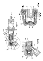
- Fig. 1 eine seitliche Teilquerschnittsansicht eines Geberzylinders gemäß der vorliegenden Erfindung zeigt;
- Fig. 2 zeigt vergrößert den durch einen Kreis markierten Endteil von Fig. 1 ;
- Fig. 3 zeigt vergrößert die inneren Einzelheiten der in den Figuren 1 und 2 dargestellten Dämpfungsvorrichtung;
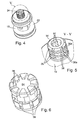
- Fig. 4 und 5 zeigen perspektivische Ansichten eines Endteils eines Hauptkörperteils des Schwingungsdämpfers und
- Fig. 6 zeigt eine perspektivische Ansicht der äußeren Einzelheiten einer an den Hauptkörperteil des Schwingungsdämpfers angepassten Verschlusskappe , welche eine Membran des Schwingungsdämpfers einschließt.
- Die Zeichnungen zeigen, dass ein Geberzylinder 10 einen Grundkörper 11 mit einer Bohrung 12 aufweist, in welcher ein Kolben 13 unter Einwirkung einer Kolbenstange 14 hin- und hergleiten kann, die mit einem entsprechenden (nicht dargestellten) Kupplungspedal verbunden ist. Der Grundkörper 11 weist eine Einlassöffnung 15, die mit einem (nicht dargestellten) Flüssigkeitsbehälter verbunden ist, und eine Auslassöffnung 16 auf, die über eine (nicht dargestellte) Leitung mit einem Kupplungsnehmerzylinder verbunden ist.
- In Fig. 1 befindet sich vom Kolben 13 aus gesehen auf der linken Seite eine Druckkammer 17, aus der durch eine Arbeitsbewegung des Kolbens 13 eine unter Druck stehende Flüssigkeit nach der in Fig. 1 gezeigten linken Seite verdrängt wird.
- Gemäß der vorliegenden Erfindung ist am linken Ende in der Bohrung 12 ein zweistufiger Flüssigkeitsschwingungsdämpfer 18 untergebracht. Der Schwingungsdämpfer 18 umfasst einen im Allgemeinen zylindrischen Hauptschwingungsdämpfungskörper 19, der zur Bohrung 12 hin durch einen O-Ring (oder eine andere geeignete Dichtung) abgedichtet ist, und eine Durchgangsbohrung 21, weiterhin einen ringförmigen schlanken Teil 22 und eine Radialbohrung 23, welche den schlanken Teil 22 mit der Durchgangsbohrung 21 verbindet. Der schlanke Teil 22 ist so auf die Auslassöffnung 16 ausgerichtet, dass die Flüssigkeit aus der Druckkammer 17 über die Durchgangsbohrung 21, die radiale Bohrung 23 und den schlanken Teil 22 zur Auslassöffnung 16 verdrängt wird.
- Am Ende des Hauptschwingungsdämpfungskörpers 19 ist eine Verschlusskappe 24 angebracht, welche eine hutförmige flexible Membran 25 umschließt. Die Membran 25 weist einen ringförmigen Flanschteil 26 auf, der eine Öffnung 27 in der Membran 25 umgibt und fest zwischen den einander gegenüber liegenden ringförmigen Rändern 28 und 29 des Hauptschwingungsdämpfungskörpers 19 bzw. der Verschlusskappe 24 eingeschlossen ist. Die Verschlusskappe 24 ist mit einer Innennut 30 versehen, welche um die Membran 25 herum ein Luftpolster bildet. Zwischen der Verschlusskappe 24 und dem Basisteil 33 der Membran 25 befindet sich ein weiteres Luftpolster 32.
- Ein Endteil 34 des Hauptschwingungsdämpferkörpers 19 des Schwingungsdämpfers 18 ragt durch die Öffnung 27 der Membran und weist Außenrippen 35 auf, die Nuten 36 definieren, durch welche radiale Bohrungen 37 zur Durchgangsbohrung 21 führen. Die Nuten 36 werden durch axiale Schlitze 36a miteinander verbunden. Durch diese Rippen, Nuten, Schlitze und Löcher wird verhindert, dass zwischen dem Endteil 34 des Hauptschwingungsdämpfungskörpers und der Innenfläche der umgebenden Membran 25 Luft eingeschlossen wird. Das ist besonders dann von Bedeutung, wenn das Hydrauliksystem das erste Mal entlüftet wird, um die eingeschlossene Luft zu entfernen.
- Die Außenfläche der Verschlusskappe 24 ist ebenfalls mit einer Reihe von Schlitzen 38 und Nuten 39 versehen, welche verhindern, dass zwischen der Verschlusskappe 24 und der umgebenden Bohrung 12 Luft eingeschlossen wird. Auf diese Weise ist die gesamte Außenfläche der Verschlusskappe 24 von unter Druck stehender Flüssigkeit umgeben, sodass die auf die Verschlusskappe 24 einwirkende Gesamtspannung verringert wird. Die Verschlusskappe 24 und der Hauptschwingungsdämpfungskörper 19 werden durch eine zwischen dem Kolben 13 und dem Hauptschwingungsdämpfungskörper 19 wirkende Kolbenrückholfeder 13a gegen das Ende der Bohrung 12 gedrückt.
- Der oben beschriebene Schwingungsdämpfer 18 arbeitet wie folgt. Der Geberzylinder 10 wird durch Niederdrücken des Kupplungspedals betätigt, welches die Kolbenstange 14 in der oben beschriebenen Weise nach links verschiebt. Hierdurch wird wiederum der Kolben 13 nach links verschoben, wobei die unter Druck stehende Flüssigkeit über die Durchgangsbohrung 21, die radiale Bohrung 23 und den schlanken Teil 22 zur Auslassöffnung 16 hin verdrängt wird. Die Schwingungen, die auf die Arbeitsflüssigkeit des Systems übertragen werden, zum Beispiel von dem mit der Auslassöffnung 16 verbundenen zugehörigen Nehmerzylinder, gelangen zum schlanken Teil 22 des Hauptschwingungsdämpfungskörper 19. Vom schlanken Teil 22 aus werden diese Schwingungen durch die radiale Bohrung 23, welche einen kleineren Durchmesser als die Durchgangsbohrung 21 aufweist und daher schwingungsdämpfend wirkt, und weiter über die Durchgangsbohrung 21 zur Öffnung 27 in der Membran 25 geleitet, sodass die Membran in die Luftpolster 31 und 32 ausweicht und somit diese Schwingungen weiter dämpft. Somit erfolgt eine zweistufige Schwingungsdämpfung, wobei die erste Stufe durch das Durchtreten der schwingenden Flüssigkeit durch die Bohrung 23 mit dem kleineren Durchmesser und die zweite Stufe durch das Drücken der Membran 25 in die Luftpolster 31 und 32 erreicht wird. Es ist klar, dass der Hauptschwingungsdämpfungskörper 19 äußerst kompakt ist und in das vorhandene Ende der Bohrung 12 eingepasst werden kann.
- Dies ist von besonderem Vorteil, wenn der Geberzylinder 10 in einem Fahrzeug mit beengtem Fahrgastraum verwendet werden soll.
Claims (8)
- Geberzylinder (10), der einen Grundkörper (11) mit einem Kolben (13) aufweist, welcher in einer Bohrung (12) gleiten kann und vor dem Kolben (13) eine Druckkammer (17) definiert, in welcher eine Arbeitsflüssigkeit mit Druck beaufschlagt wird, wobei im Grundkörper (11) ein zweistufiger hydraulischer Schwingungsdämpfer (18) untergebracht ist, der aus einer Kammer mit veränderlichem Volumen besteht, die zur Dämpfung der Schwingungen in der Arbeitsflüssigkeit über ein Drosselmittel mit der Druckkammer (17) verbunden ist.
- Geberzylinder nach Anspruch 1, dadurch gekennzeichnet, dass sich die Kammer mit veränderlichem Volumen in der Bohrung (12) des Grundkörpers (11) befindet.
- Geberzylinder nach Anspruch 1 oder 2, dadurch gekennzeichnet, dass die Kammer mit veränderlichem Volumen durch eine flexible Membran (25), die in einen zwischen zwei Teilen eines in der Bohrung (12) befindlichen Schwingungsdämpfungskörpers (19) gebildeten Hohlraum eingeschlossen ist, und wobei ein oder mehrere Luftpolster zwischen der Außenfläche der Membran (25) und dem Hohlraum bereitgestellt wird, in welche die Membran (25) ausweichen und die Schwingungen in der Arbeitsflüssigkeit dämpfen kann.
- Geberzylinder nach Anspruch 3, dadurch gekennzeichnet, dass der Dämpfungshohlraum, welcher die Membran (25) aufnimmt, zwischen einem Hauptschwingungsdämpfungskörper (19) und einer umgebenden Verschlusskappe (24) bereitgestellt wird, welche die Membran (25) umschließt und am Hauptschwingungsdämpfungskörper (19) befestigt ist.
- Geberzylinder nach Anspruch 4, dadurch gekennzeichnet, dass die Membran fest zwischen den Hauptschwingungsdämpfungskörper (19) und der Verschlusskappe (24) eingeschlossen ist, wobei die Membran (25) einen ringförmigen Flansch (26) aufweist, der ein offenes Ende der Membran (25) umgibt und zwischen einander gegenüber liegenden ringförmigen Rändern der Verschlusskappe (24) und des Hauptschwingungs-dämpfungskörpers (19) eingeschlossen ist.
- Geberzylinder nach Anspruch 4 oder 5, dadurch gekennzeichnet, dass ein Teil des Hauptschwingungsdämpfungskörpers (19) durch das offene Ende der Membran (25) ragt und eine Vielzahl von Löchern/Nuten (35,36,37) zum Entlüften des Geberzylinders (10) enthalten kann, damit zwischen dem herausragenden Teil des Hauptschwingungsdämpfungskörpers (19) und der Innenseite der umgebenden Membran (25) keine Luft eingeschlossen ist.
- Geberzylinder nach einem der Ansprüche 4 bis 6, dadurch gekennzeichnet, dass die Außenseite der Verschlusskappe (24) mit Schlitzen (38) versehen ist, damit zwischen der Verschlusskappe (24) und der Bohrung (12), in welcher sich die Verschlusskappe (24) befindet, keine Luft eingeschlossen wird.
- Geberzylinder, der im Wesentlichen so aufgebaut und angeordnet ist, wie oben unter Bezug auf die beiliegenden Zeichnungen beschrieben und in den beiliegenden Zeichnungen dargestellt.
Applications Claiming Priority (1)
| Application Number | Priority Date | Filing Date | Title |
|---|---|---|---|
| GB0420890A GB0420890D0 (en) | 2004-09-21 | 2004-09-21 | Hydraulic actuators |
Publications (2)
| Publication Number | Publication Date |
|---|---|
| EP1637793A1 true EP1637793A1 (de) | 2006-03-22 |
| EP1637793B1 EP1637793B1 (de) | 2009-08-12 |
Family
ID=33306895
Family Applications (1)
| Application Number | Title | Priority Date | Filing Date |
|---|---|---|---|
| EP05020335A Expired - Lifetime EP1637793B1 (de) | 2004-09-21 | 2005-09-17 | Hydraulischer Aktuator mit Schwingungsdämpfer |
Country Status (4)
| Country | Link |
|---|---|
| EP (1) | EP1637793B1 (de) |
| AT (1) | ATE439546T1 (de) |
| DE (2) | DE502005007880D1 (de) |
| GB (1) | GB0420890D0 (de) |
Cited By (3)
| Publication number | Priority date | Publication date | Assignee | Title |
|---|---|---|---|---|
| CN103742558A (zh) * | 2013-12-31 | 2014-04-23 | 芜湖聚达汽车零部件有限公司 | 一种离合器消声阀 |
| WO2017140306A1 (de) * | 2016-02-18 | 2017-08-24 | Schaeffler Technologies AG & Co. KG | Kupplungsgeberzylinder mit dämpfer |
| CN114810868A (zh) * | 2022-01-21 | 2022-07-29 | 覃美强 | 一种新能源汽车制动刹车钳 |
Families Citing this family (3)
| Publication number | Priority date | Publication date | Assignee | Title |
|---|---|---|---|---|
| DE102009049245A1 (de) | 2008-11-06 | 2010-05-12 | Luk Lamellen Und Kupplungsbau Beteiligungs Kg | Rückschlagventileinrichtung |
| DE102009005828A1 (de) | 2009-01-22 | 2010-07-29 | Fte Automotive Gmbh | Nehmerzylinder für ein schwingungsgedämpftes hydraulisches Kraftübertragungssystem, insbesondere eine hydraulische Kupplungsbetätigung für Kraftfahrzeuge |
| DE112018002402A5 (de) * | 2017-05-10 | 2020-01-23 | Schaeffler Technologies AG & Co. KG | Geberzylinder mit definierter Volumenänderung zur Schwingungsdämpfung |
Citations (5)
| Publication number | Priority date | Publication date | Assignee | Title |
|---|---|---|---|---|
| JPS62200034A (ja) * | 1986-02-27 | 1987-09-03 | Hino Motors Ltd | クラツチコントロ−ル系統の振動防止装置 |
| DE3807954A1 (de) * | 1988-03-10 | 1989-09-21 | Kugelfischer G Schaefer & Co | Daempfungselement |
| US5320203A (en) * | 1990-01-16 | 1994-06-14 | Automotive Products Plc | Damper for hydraulic clutch actuator |
| US6669309B1 (en) * | 1998-12-09 | 2003-12-30 | Zf Friedrichshafen Ag | vibration damper for damping fluid vibrations in a hydraulic system |
| US6789388B1 (en) * | 2000-07-20 | 2004-09-14 | Automotive Products (Usa), Inc. | Triple action damper for hydraulic clutch actuator |
Family Cites Families (1)
| Publication number | Priority date | Publication date | Assignee | Title |
|---|---|---|---|---|
| DE19807446B4 (de) * | 1998-02-24 | 2004-09-09 | Zf Sachs Ag | Dämpfungsglied für hydraulische Verstelleinrichtungen bei Kraftfahrzeugen |
-
2004
- 2004-09-21 GB GB0420890A patent/GB0420890D0/en not_active Ceased
-
2005
- 2005-09-17 DE DE502005007880T patent/DE502005007880D1/de not_active Expired - Lifetime
- 2005-09-17 EP EP05020335A patent/EP1637793B1/de not_active Expired - Lifetime
- 2005-09-17 AT AT05020335T patent/ATE439546T1/de not_active IP Right Cessation
- 2005-09-17 DE DE102005044582.9A patent/DE102005044582B4/de not_active Expired - Fee Related
Patent Citations (5)
| Publication number | Priority date | Publication date | Assignee | Title |
|---|---|---|---|---|
| JPS62200034A (ja) * | 1986-02-27 | 1987-09-03 | Hino Motors Ltd | クラツチコントロ−ル系統の振動防止装置 |
| DE3807954A1 (de) * | 1988-03-10 | 1989-09-21 | Kugelfischer G Schaefer & Co | Daempfungselement |
| US5320203A (en) * | 1990-01-16 | 1994-06-14 | Automotive Products Plc | Damper for hydraulic clutch actuator |
| US6669309B1 (en) * | 1998-12-09 | 2003-12-30 | Zf Friedrichshafen Ag | vibration damper for damping fluid vibrations in a hydraulic system |
| US6789388B1 (en) * | 2000-07-20 | 2004-09-14 | Automotive Products (Usa), Inc. | Triple action damper for hydraulic clutch actuator |
Cited By (4)
| Publication number | Priority date | Publication date | Assignee | Title |
|---|---|---|---|---|
| CN103742558A (zh) * | 2013-12-31 | 2014-04-23 | 芜湖聚达汽车零部件有限公司 | 一种离合器消声阀 |
| WO2017140306A1 (de) * | 2016-02-18 | 2017-08-24 | Schaeffler Technologies AG & Co. KG | Kupplungsgeberzylinder mit dämpfer |
| CN114810868A (zh) * | 2022-01-21 | 2022-07-29 | 覃美强 | 一种新能源汽车制动刹车钳 |
| CN114810868B (zh) * | 2022-01-21 | 2024-04-12 | 宝鸡鑫龙余管营汽车零部件有限公司 | 一种新能源汽车制动刹车钳 |
Also Published As
| Publication number | Publication date |
|---|---|
| DE102005044582B4 (de) | 2015-07-16 |
| DE502005007880D1 (de) | 2009-09-24 |
| EP1637793B1 (de) | 2009-08-12 |
| ATE439546T1 (de) | 2009-08-15 |
| GB0420890D0 (en) | 2004-10-20 |
| DE102005044582A1 (de) | 2006-04-06 |
Similar Documents
| Publication | Publication Date | Title |
|---|---|---|
| EP1233891B2 (de) | Simulator für ein nichthydraulisches betätigungssystem | |
| DE3434033C2 (de) | ||
| DE102013006990B4 (de) | Druckdämpfungsvorrichtung für Bremssystem | |
| DE102017200647B4 (de) | Bremssystem | |
| DE10214145A1 (de) | Bremshubsimulator und mit diesem versehene hydraulische Fahrzeugbremse | |
| DE19543698C1 (de) | Bremsgestänge und Hauptbremszylinder | |
| DE10311060B4 (de) | Bremskrafterzeuger für eine hydraulische Kraftfahrzeugbremsanlage und hydraulische Kraftfahrzeugbremsanlage | |
| DE19833410B4 (de) | Hydraulische Ansteuereinheit für eine Kraftfahrzeugbremsanlage | |
| EP1569831B1 (de) | Pedalsimulationseinrichtung | |
| EP1525408B1 (de) | Hydraulisches betätigungssystem | |
| DE112023004789T5 (de) | Dämpfungsvorrichtung, Flüssigkeitsdruck-Steuereinheit und Bremssystem | |
| DE102017209618A1 (de) | Pedalwegsimulator für eine hydraulische Fremdkraft-Fahrzeugbremsanlage | |
| EP1637793B1 (de) | Hydraulischer Aktuator mit Schwingungsdämpfer | |
| DE102018221757A1 (de) | Bremssystem, enthaltend einen Hauptzylinder mit einem elastischenPedalgefühlelement | |
| DE10358321B4 (de) | Hydraulische Pedalsimulationsvorrichtung | |
| EP1719921A2 (de) | Zwischen einen Geber- und einen Nehmerzylinder eines hydraulischen Kraftübertragungssystems schaltbare Ventilanordnung zur Schwingungsentkopplung | |
| DE6914011U (de) | Drucksteuerventil fuer die zu den hinterraedern gehende druckleitung einer in einem kraftfahrzeug eingebauten hydraulischen bremsanlage | |
| DE2444403A1 (de) | Bremskraftregler | |
| DE10258266A1 (de) | Betätigungseinheit | |
| DE10164319C2 (de) | Betätigungseinheit für eine hydraulische Fahrzeugbremsanlage | |
| EP3548347A1 (de) | Hauptbremszylinder, bremsanlage | |
| DE69328075T2 (de) | Steuerventil für eine hydraulische Bremsanlage | |
| WO2002064411A2 (de) | Bremskraftübertragungseinrichtung für einen bremskraftverstärker | |
| DE2830223A1 (de) | Tandemhauptzylinder | |
| DE10352941A1 (de) | Druckmittelzylinder für eine hydraulische Betätigunseinrichtung |
Legal Events
| Date | Code | Title | Description |
|---|---|---|---|
| PUAI | Public reference made under article 153(3) epc to a published international application that has entered the european phase |
Free format text: ORIGINAL CODE: 0009012 |
|
| AK | Designated contracting states |
Kind code of ref document: A1 Designated state(s): AT BE BG CH CY CZ DE DK EE ES FI FR GB GR HU IE IS IT LI LT LU LV MC NL PL PT RO SE SI SK TR |
|
| AX | Request for extension of the european patent |
Extension state: AL BA HR MK YU |
|
| 17P | Request for examination filed |
Effective date: 20060922 |
|
| 17Q | First examination report despatched |
Effective date: 20061018 |
|
| AKX | Designation fees paid |
Designated state(s): AT BE BG CH CY CZ DE DK EE ES FI FR GB GR HU IE IS IT LI LT LU LV MC NL PL PT RO SE SI SK TR |
|
| 17Q | First examination report despatched |
Effective date: 20061018 |
|
| GRAP | Despatch of communication of intention to grant a patent |
Free format text: ORIGINAL CODE: EPIDOSNIGR1 |
|
| GRAS | Grant fee paid |
Free format text: ORIGINAL CODE: EPIDOSNIGR3 |
|
| GRAA | (expected) grant |
Free format text: ORIGINAL CODE: 0009210 |
|
| AK | Designated contracting states |
Kind code of ref document: B1 Designated state(s): AT BE BG CH CY CZ DE DK EE ES FI FR GB GR HU IE IS IT LI LT LU LV MC NL PL PT RO SE SI SK TR |
|
| REG | Reference to a national code |
Ref country code: GB Ref legal event code: FG4D Free format text: NOT ENGLISH |
|
| REG | Reference to a national code |
Ref country code: CH Ref legal event code: EP |
|
| REG | Reference to a national code |
Ref country code: IE Ref legal event code: FG4D |
|
| REF | Corresponds to: |
Ref document number: 502005007880 Country of ref document: DE Date of ref document: 20090924 Kind code of ref document: P |
|
| LTIE | Lt: invalidation of european patent or patent extension |
Effective date: 20090812 |
|
| PG25 | Lapsed in a contracting state [announced via postgrant information from national office to epo] |
Ref country code: SE Free format text: LAPSE BECAUSE OF FAILURE TO SUBMIT A TRANSLATION OF THE DESCRIPTION OR TO PAY THE FEE WITHIN THE PRESCRIBED TIME-LIMIT Effective date: 20090812 Ref country code: LT Free format text: LAPSE BECAUSE OF FAILURE TO SUBMIT A TRANSLATION OF THE DESCRIPTION OR TO PAY THE FEE WITHIN THE PRESCRIBED TIME-LIMIT Effective date: 20090812 Ref country code: FI Free format text: LAPSE BECAUSE OF FAILURE TO SUBMIT A TRANSLATION OF THE DESCRIPTION OR TO PAY THE FEE WITHIN THE PRESCRIBED TIME-LIMIT Effective date: 20090812 Ref country code: ES Free format text: LAPSE BECAUSE OF FAILURE TO SUBMIT A TRANSLATION OF THE DESCRIPTION OR TO PAY THE FEE WITHIN THE PRESCRIBED TIME-LIMIT Effective date: 20091123 Ref country code: IS Free format text: LAPSE BECAUSE OF FAILURE TO SUBMIT A TRANSLATION OF THE DESCRIPTION OR TO PAY THE FEE WITHIN THE PRESCRIBED TIME-LIMIT Effective date: 20091212 |
|
| NLV1 | Nl: lapsed or annulled due to failure to fulfill the requirements of art. 29p and 29m of the patents act | ||
| PG25 | Lapsed in a contracting state [announced via postgrant information from national office to epo] |
Ref country code: SI Free format text: LAPSE BECAUSE OF FAILURE TO SUBMIT A TRANSLATION OF THE DESCRIPTION OR TO PAY THE FEE WITHIN THE PRESCRIBED TIME-LIMIT Effective date: 20090812 Ref country code: NL Free format text: LAPSE BECAUSE OF FAILURE TO SUBMIT A TRANSLATION OF THE DESCRIPTION OR TO PAY THE FEE WITHIN THE PRESCRIBED TIME-LIMIT Effective date: 20090812 Ref country code: PL Free format text: LAPSE BECAUSE OF FAILURE TO SUBMIT A TRANSLATION OF THE DESCRIPTION OR TO PAY THE FEE WITHIN THE PRESCRIBED TIME-LIMIT Effective date: 20090812 Ref country code: LV Free format text: LAPSE BECAUSE OF FAILURE TO SUBMIT A TRANSLATION OF THE DESCRIPTION OR TO PAY THE FEE WITHIN THE PRESCRIBED TIME-LIMIT Effective date: 20090812 |
|
| REG | Reference to a national code |
Ref country code: IE Ref legal event code: FD4D |
|
| BERE | Be: lapsed |
Owner name: LUK LAMELLEN UND KUPPLUNGSBAU BETEILIGUNGS K.G. Effective date: 20090930 |
|
| PG25 | Lapsed in a contracting state [announced via postgrant information from national office to epo] |
Ref country code: BG Free format text: LAPSE BECAUSE OF FAILURE TO SUBMIT A TRANSLATION OF THE DESCRIPTION OR TO PAY THE FEE WITHIN THE PRESCRIBED TIME-LIMIT Effective date: 20091112 Ref country code: PT Free format text: LAPSE BECAUSE OF FAILURE TO SUBMIT A TRANSLATION OF THE DESCRIPTION OR TO PAY THE FEE WITHIN THE PRESCRIBED TIME-LIMIT Effective date: 20091212 |
|
| PG25 | Lapsed in a contracting state [announced via postgrant information from national office to epo] |
Ref country code: RO Free format text: LAPSE BECAUSE OF FAILURE TO SUBMIT A TRANSLATION OF THE DESCRIPTION OR TO PAY THE FEE WITHIN THE PRESCRIBED TIME-LIMIT Effective date: 20090812 Ref country code: MC Free format text: LAPSE BECAUSE OF NON-PAYMENT OF DUE FEES Effective date: 20090930 Ref country code: CZ Free format text: LAPSE BECAUSE OF FAILURE TO SUBMIT A TRANSLATION OF THE DESCRIPTION OR TO PAY THE FEE WITHIN THE PRESCRIBED TIME-LIMIT Effective date: 20090812 Ref country code: EE Free format text: LAPSE BECAUSE OF FAILURE TO SUBMIT A TRANSLATION OF THE DESCRIPTION OR TO PAY THE FEE WITHIN THE PRESCRIBED TIME-LIMIT Effective date: 20090812 Ref country code: DK Free format text: LAPSE BECAUSE OF FAILURE TO SUBMIT A TRANSLATION OF THE DESCRIPTION OR TO PAY THE FEE WITHIN THE PRESCRIBED TIME-LIMIT Effective date: 20090812 Ref country code: IE Free format text: LAPSE BECAUSE OF FAILURE TO SUBMIT A TRANSLATION OF THE DESCRIPTION OR TO PAY THE FEE WITHIN THE PRESCRIBED TIME-LIMIT Effective date: 20090812 |
|
| REG | Reference to a national code |
Ref country code: CH Ref legal event code: PL |
|
| PG25 | Lapsed in a contracting state [announced via postgrant information from national office to epo] |
Ref country code: SK Free format text: LAPSE BECAUSE OF FAILURE TO SUBMIT A TRANSLATION OF THE DESCRIPTION OR TO PAY THE FEE WITHIN THE PRESCRIBED TIME-LIMIT Effective date: 20090812 |
|
| PLBE | No opposition filed within time limit |
Free format text: ORIGINAL CODE: 0009261 |
|
| STAA | Information on the status of an ep patent application or granted ep patent |
Free format text: STATUS: NO OPPOSITION FILED WITHIN TIME LIMIT |
|
| 26N | No opposition filed |
Effective date: 20100517 |
|
| GBPC | Gb: european patent ceased through non-payment of renewal fee |
Effective date: 20091112 |
|
| PG25 | Lapsed in a contracting state [announced via postgrant information from national office to epo] |
Ref country code: BE Free format text: LAPSE BECAUSE OF NON-PAYMENT OF DUE FEES Effective date: 20090930 |
|
| PG25 | Lapsed in a contracting state [announced via postgrant information from national office to epo] |
Ref country code: LI Free format text: LAPSE BECAUSE OF NON-PAYMENT OF DUE FEES Effective date: 20090930 Ref country code: CH Free format text: LAPSE BECAUSE OF NON-PAYMENT OF DUE FEES Effective date: 20090930 Ref country code: GR Free format text: LAPSE BECAUSE OF FAILURE TO SUBMIT A TRANSLATION OF THE DESCRIPTION OR TO PAY THE FEE WITHIN THE PRESCRIBED TIME-LIMIT Effective date: 20091113 |
|
| PG25 | Lapsed in a contracting state [announced via postgrant information from national office to epo] |
Ref country code: AT Free format text: LAPSE BECAUSE OF NON-PAYMENT OF DUE FEES Effective date: 20090917 |
|
| PG25 | Lapsed in a contracting state [announced via postgrant information from national office to epo] |
Ref country code: GB Free format text: LAPSE BECAUSE OF NON-PAYMENT OF DUE FEES Effective date: 20091112 |
|
| PG25 | Lapsed in a contracting state [announced via postgrant information from national office to epo] |
Ref country code: IT Free format text: LAPSE BECAUSE OF FAILURE TO SUBMIT A TRANSLATION OF THE DESCRIPTION OR TO PAY THE FEE WITHIN THE PRESCRIBED TIME-LIMIT Effective date: 20090812 |
|
| PG25 | Lapsed in a contracting state [announced via postgrant information from national office to epo] |
Ref country code: LU Free format text: LAPSE BECAUSE OF NON-PAYMENT OF DUE FEES Effective date: 20090917 |
|
| REG | Reference to a national code |
Ref country code: FR Ref legal event code: ST Effective date: 20110531 |
|
| PG25 | Lapsed in a contracting state [announced via postgrant information from national office to epo] |
Ref country code: HU Free format text: LAPSE BECAUSE OF FAILURE TO SUBMIT A TRANSLATION OF THE DESCRIPTION OR TO PAY THE FEE WITHIN THE PRESCRIBED TIME-LIMIT Effective date: 20100213 |
|
| PG25 | Lapsed in a contracting state [announced via postgrant information from national office to epo] |
Ref country code: FR Free format text: LAPSE BECAUSE OF NON-PAYMENT OF DUE FEES Effective date: 20100930 |
|
| PG25 | Lapsed in a contracting state [announced via postgrant information from national office to epo] |
Ref country code: TR Free format text: LAPSE BECAUSE OF FAILURE TO SUBMIT A TRANSLATION OF THE DESCRIPTION OR TO PAY THE FEE WITHIN THE PRESCRIBED TIME-LIMIT Effective date: 20090812 |
|
| PG25 | Lapsed in a contracting state [announced via postgrant information from national office to epo] |
Ref country code: CY Free format text: LAPSE BECAUSE OF FAILURE TO SUBMIT A TRANSLATION OF THE DESCRIPTION OR TO PAY THE FEE WITHIN THE PRESCRIBED TIME-LIMIT Effective date: 20090812 |
|
| PGFP | Annual fee paid to national office [announced via postgrant information from national office to epo] |
Ref country code: FR Payment date: 20091006 Year of fee payment: 5 |
|
| REG | Reference to a national code |
Ref country code: DE Ref legal event code: R081 Ref document number: 502005007880 Country of ref document: DE Owner name: SCHAEFFLER TECHNOLOGIES AG & CO. KG, DE Free format text: FORMER OWNER: SCHAEFFLER TECHNOLOGIES GMBH & CO. KG, 91074 HERZOGENAURACH, DE Effective date: 20120828 Ref country code: DE Ref legal event code: R081 Ref document number: 502005007880 Country of ref document: DE Owner name: SCHAEFFLER TECHNOLOGIES GMBH & CO. KG, DE Free format text: FORMER OWNER: SCHAEFFLER TECHNOLOGIES GMBH & CO. KG, 91074 HERZOGENAURACH, DE Effective date: 20120828 |
|
| REG | Reference to a national code |
Ref country code: DE Ref legal event code: R081 Ref document number: 502005007880 Country of ref document: DE Owner name: SCHAEFFLER TECHNOLOGIES AG & CO. KG, DE Free format text: FORMER OWNER: SCHAEFFLER TECHNOLOGIES AG & CO. KG, 91074 HERZOGENAURACH, DE Effective date: 20140218 Ref country code: DE Ref legal event code: R081 Ref document number: 502005007880 Country of ref document: DE Owner name: SCHAEFFLER TECHNOLOGIES GMBH & CO. KG, DE Free format text: FORMER OWNER: SCHAEFFLER TECHNOLOGIES AG & CO. KG, 91074 HERZOGENAURACH, DE Effective date: 20140218 |
|
| REG | Reference to a national code |
Ref country code: DE Ref legal event code: R081 Ref document number: 502005007880 Country of ref document: DE Owner name: SCHAEFFLER TECHNOLOGIES AG & CO. KG, DE Free format text: FORMER OWNER: SCHAEFFLER TECHNOLOGIES GMBH & CO. KG, 91074 HERZOGENAURACH, DE Effective date: 20150213 |
|
| PGFP | Annual fee paid to national office [announced via postgrant information from national office to epo] |
Ref country code: DE Payment date: 20171130 Year of fee payment: 13 |
|
| REG | Reference to a national code |
Ref country code: DE Ref legal event code: R119 Ref document number: 502005007880 Country of ref document: DE |
|
| PG25 | Lapsed in a contracting state [announced via postgrant information from national office to epo] |
Ref country code: DE Free format text: LAPSE BECAUSE OF NON-PAYMENT OF DUE FEES Effective date: 20190402 |
|
| P01 | Opt-out of the competence of the unified patent court (upc) registered |
Effective date: 20230524 |