EP1637388A2 - Vehicle stability control system - Google Patents
Vehicle stability control system Download PDFInfo
- Publication number
- EP1637388A2 EP1637388A2 EP05017427A EP05017427A EP1637388A2 EP 1637388 A2 EP1637388 A2 EP 1637388A2 EP 05017427 A EP05017427 A EP 05017427A EP 05017427 A EP05017427 A EP 05017427A EP 1637388 A2 EP1637388 A2 EP 1637388A2
- Authority
- EP
- European Patent Office
- Prior art keywords
- vibration
- physical quantity
- vehicle
- engine
- control system
- Prior art date
- Legal status (The legal status is an assumption and is not a legal conclusion. Google has not performed a legal analysis and makes no representation as to the accuracy of the status listed.)
- Withdrawn
Links
Images


Classifications
-
- B—PERFORMING OPERATIONS; TRANSPORTING
- B60—VEHICLES IN GENERAL
- B60W—CONJOINT CONTROL OF VEHICLE SUB-UNITS OF DIFFERENT TYPE OR DIFFERENT FUNCTION; CONTROL SYSTEMS SPECIALLY ADAPTED FOR HYBRID VEHICLES; ROAD VEHICLE DRIVE CONTROL SYSTEMS FOR PURPOSES NOT RELATED TO THE CONTROL OF A PARTICULAR SUB-UNIT
- B60W10/00—Conjoint control of vehicle sub-units of different type or different function
- B60W10/04—Conjoint control of vehicle sub-units of different type or different function including control of propulsion units
- B60W10/08—Conjoint control of vehicle sub-units of different type or different function including control of propulsion units including control of electric propulsion units, e.g. motors or generators
-
- B—PERFORMING OPERATIONS; TRANSPORTING
- B60—VEHICLES IN GENERAL
- B60G—VEHICLE SUSPENSION ARRANGEMENTS
- B60G2400/00—Indexing codes relating to detected, measured or calculated conditions or factors
- B60G2400/05—Attitude
- B60G2400/051—Angle
- B60G2400/0512—Pitch angle
-
- B—PERFORMING OPERATIONS; TRANSPORTING
- B60—VEHICLES IN GENERAL
- B60G—VEHICLE SUSPENSION ARRANGEMENTS
- B60G2400/00—Indexing codes relating to detected, measured or calculated conditions or factors
- B60G2400/05—Attitude
- B60G2400/053—Angular acceleration
- B60G2400/0532—Pitch acceleration
-
- B—PERFORMING OPERATIONS; TRANSPORTING
- B60—VEHICLES IN GENERAL
- B60G—VEHICLE SUSPENSION ARRANGEMENTS
- B60G2800/00—Indexing codes relating to the type of movement or to the condition of the vehicle and to the end result to be achieved by the control action
- B60G2800/01—Attitude or posture control
- B60G2800/014—Pitch; Nose dive
-
- B—PERFORMING OPERATIONS; TRANSPORTING
- B60—VEHICLES IN GENERAL
- B60W—CONJOINT CONTROL OF VEHICLE SUB-UNITS OF DIFFERENT TYPE OR DIFFERENT FUNCTION; CONTROL SYSTEMS SPECIALLY ADAPTED FOR HYBRID VEHICLES; ROAD VEHICLE DRIVE CONTROL SYSTEMS FOR PURPOSES NOT RELATED TO THE CONTROL OF A PARTICULAR SUB-UNIT
- B60W30/00—Purposes of road vehicle drive control systems not related to the control of a particular sub-unit, e.g. of systems using conjoint control of vehicle sub-units
- B60W30/02—Control of vehicle driving stability
- B60W30/04—Control of vehicle driving stability related to roll-over prevention
- B60W2030/041—Control of vehicle driving stability related to roll-over prevention about the pitch axis
-
- B—PERFORMING OPERATIONS; TRANSPORTING
- B60—VEHICLES IN GENERAL
- B60W—CONJOINT CONTROL OF VEHICLE SUB-UNITS OF DIFFERENT TYPE OR DIFFERENT FUNCTION; CONTROL SYSTEMS SPECIALLY ADAPTED FOR HYBRID VEHICLES; ROAD VEHICLE DRIVE CONTROL SYSTEMS FOR PURPOSES NOT RELATED TO THE CONTROL OF A PARTICULAR SUB-UNIT
- B60W40/00—Estimation or calculation of non-directly measurable driving parameters for road vehicle drive control systems not related to the control of a particular sub unit, e.g. by using mathematical models
- B60W40/12—Estimation or calculation of non-directly measurable driving parameters for road vehicle drive control systems not related to the control of a particular sub unit, e.g. by using mathematical models related to parameters of the vehicle itself, e.g. tyre models
- B60W40/13—Load or weight
- B60W2040/1323—Moment of inertia of the vehicle body
- B60W2040/1338—Moment of inertia of the vehicle body about the pitch axis
-
- B—PERFORMING OPERATIONS; TRANSPORTING
- B60—VEHICLES IN GENERAL
- B60W—CONJOINT CONTROL OF VEHICLE SUB-UNITS OF DIFFERENT TYPE OR DIFFERENT FUNCTION; CONTROL SYSTEMS SPECIALLY ADAPTED FOR HYBRID VEHICLES; ROAD VEHICLE DRIVE CONTROL SYSTEMS FOR PURPOSES NOT RELATED TO THE CONTROL OF A PARTICULAR SUB-UNIT
- B60W40/00—Estimation or calculation of non-directly measurable driving parameters for road vehicle drive control systems not related to the control of a particular sub unit, e.g. by using mathematical models
- B60W40/10—Estimation or calculation of non-directly measurable driving parameters for road vehicle drive control systems not related to the control of a particular sub unit, e.g. by using mathematical models related to vehicle motion
- B60W40/11—Pitch movement
-
- B—PERFORMING OPERATIONS; TRANSPORTING
- B60—VEHICLES IN GENERAL
- B60W—CONJOINT CONTROL OF VEHICLE SUB-UNITS OF DIFFERENT TYPE OR DIFFERENT FUNCTION; CONTROL SYSTEMS SPECIALLY ADAPTED FOR HYBRID VEHICLES; ROAD VEHICLE DRIVE CONTROL SYSTEMS FOR PURPOSES NOT RELATED TO THE CONTROL OF A PARTICULAR SUB-UNIT
- B60W40/00—Estimation or calculation of non-directly measurable driving parameters for road vehicle drive control systems not related to the control of a particular sub unit, e.g. by using mathematical models
- B60W40/10—Estimation or calculation of non-directly measurable driving parameters for road vehicle drive control systems not related to the control of a particular sub unit, e.g. by using mathematical models related to vehicle motion
- B60W40/112—Roll movement
-
- B—PERFORMING OPERATIONS; TRANSPORTING
- B60—VEHICLES IN GENERAL
- B60W—CONJOINT CONTROL OF VEHICLE SUB-UNITS OF DIFFERENT TYPE OR DIFFERENT FUNCTION; CONTROL SYSTEMS SPECIALLY ADAPTED FOR HYBRID VEHICLES; ROAD VEHICLE DRIVE CONTROL SYSTEMS FOR PURPOSES NOT RELATED TO THE CONTROL OF A PARTICULAR SUB-UNIT
- B60W40/00—Estimation or calculation of non-directly measurable driving parameters for road vehicle drive control systems not related to the control of a particular sub unit, e.g. by using mathematical models
- B60W40/10—Estimation or calculation of non-directly measurable driving parameters for road vehicle drive control systems not related to the control of a particular sub unit, e.g. by using mathematical models related to vehicle motion
- B60W40/114—Yaw movement
Definitions
- the present invention relates to a vehicle stability control system for suppressing vibrations generated during running of a vehicle.
- a regenerative brake which is designed to produce braking force using a braking apparatus as well as an engine load apparatus, such as an alternator, during braking of the vehicle.
- An example of such a system is disclosed in Japanese Patent Laid-Open Publication No. Hei 10-285706.
- the regenerative brake actively turns on an engine load, such as an alternator, during braking of the vehicle in order to absorb kinetic energy of the vehicle, thereby supplementing the braking capability of the braking apparatus.
- One of the factors includes the fact that more kinetic energy may be produced than is required for the vehicle to run.
- an insufficient amount of kinetic energy may be produced. For example, assuming that the vehicle body is maintained horizontally when in a stable state, a squat may occur which causes the front of the vehicle to displace upward from the stable state due to an excessive drive torque. Additionally, a nosedive may occur which causes the front of the vehicle to displace downward from the stable state due to a drive torque reactive force generated during braking. The squat and the nosedive result from kinetic energy that is produced beyond that which is required for the vehicle to run.
- the aforementioned conventional regenerative brake is designed to impose a load on the engine to supplement the braking capability of the braking apparatus.
- the present invention was developed in view of the aforementioned and other problems.
- the principles of the present invention provide a vehicle stability control system and a method for offsetting vibrations generated during running of the vehicle.
- the system and the method are adapted to remove vibrations by establishing an engine load to absorb kinetic energy provided beyond that which is required or to supplement the engine power when the required kinetic energy cannot be obtained.
- Fig. 8 shows various kinetic energies provided by a vehicle.
- the kinetic energies of the vehicle include the pitching rotational energy, the rolling rotational energy, and the yawing rotational energy.
- the translational energy in the X-direction (along which the vehicle travels), the translational energy in the Y-direction (or the lateral direction of the vehicle), and the translational energy in the Z-direction (or the vertical direction of the vehicle).
- the pitching vibrational energy refers to the rotational vibrational energy in the pitching direction.
- the pitching direction is defined as rotating about the vehicle axis in the lateral direction with the center of gravity of the vehicle as its center.
- the pitching vibrational energy results from a squat caused during acceleration, as shown in Fig. 9A. Additionally, a nosedive caused during deceleration may occur, as shown in Fig. 9B, or during turning, as shown in Fig. 9C.
- one aspect of the present invention provides a vehicle stability control system which uses a physical quantity corresponding to a driver accelerator input to control engine power produced by an engine, as well as to controllably drive an engine load for regulating the engine power, thereby producing a desired drive force.
- the vehicle stability control system includes vibration detection means for determining a vibration during running of the vehicle.
- the system also includes correction means for driving the engine load to suppress the vibration in response to the vibration determined by the vibration detection means.
- the system drives the engine load in response to the vibration that disturbs the stability of the vehicle.
- the engine load suppresses the vibration. This makes it possible to prevent the stability of the vehicle from being disturbed due to the vibration.
- the vibration detection means can determine a vehicle body input torque and estimate the vibration based on the vehicle body input torque. More specifically, in another aspect of the present invention, the vibration detection means can detect the vibration corresponding to the vehicle body input torque in accordance with an on-spring vehicle body vibration model developed in view of the vibration of the on-spring vehicle body itself that is supported by the front and rear wheel suspensions of the vehicle.
- the correction means can subtract the physical quantity corresponding to the vibration from a physical quantity corresponding to a drive force generated by the motor to take the resulting physical quantity as a physical quantity corresponding to the proportion of the post-correction drive force for the motor generator.
- the correction means can subtract the physical quantity corresponding to the vibration from a physical quantity corresponding to a drive force reduced by the generator to take the resulting physical quantity as a physical quantity corresponding to the proportion of the post-correction drive force for the motor generator.
- a still further aspect of the present invention supposes that the engine load is a starter or an alternator.
- the correction means when the corrected vibration-based physical quantity is negative, the correction means outputs the vibration-based physical quantity as an instruction signal for driving the alternator.
- the vibration-based physical quantity When the vibration-based physical quantity is positive, the correction means outputs the vibration-based physical quantity as an instruction signal for driving the starter.
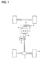
- FIG. 1 schematically shows the configuration of the vehicle stability control system according to this embodiment.
- a rear-wheel drive vehicle is used for explanatory purposes; however, the present invention is also applicable to a front-wheel drive vehicle or a four-wheel drive vehicle.
- the vehicle stability control system is configured to suppress a vibration, which may disturb the stability of the vehicle, by regulating the drive torque generated by an engine 1 included in the vehicle using a motor generator 2 serving as an engine load device to establish an engine load.
- a vibration which may disturb the stability of the vehicle
- a motor generator 2 serving as an engine load device to establish an engine load.
- the description is given to an example in which the pitching vibration is suppressed.
- Fig. 2 schematically shows the configuration of the engine ECU 3 in a block diagram.
- the engine ECU 3 includes a required drive force computational portion 3a, a pitching vibration suppression corrective portion 3b, and an actuator instruction computational portion 3c.
- a detected signal corresponding to the amount of operation of an accelerator pedal 4 is delivered from a pedal stroke sensor 5 as a physical quantity corresponding to the driver accelerator input.
- the required drive force computational portion 3a determines the amount of operation of the accelerator pedal 4 based on the detected signal, and determines the required axle shaft torque serving as a required drive force corresponding to the amount of operation.
- the drive torque required by the driver, as determined here, is to be the torque used in accelerating and decelerating the vehicle and is referred to as the required axle shaft torque.
- the required drive force computational portion 3a delivers an instructional signal to the engine 1 and the motor generator 2 in order to allow the engine 1 and the motor generator 2 to produce the axle shaft torque in accordance with their respective proportions.
- the proportion of the axle shaft torque to be generated by the motor generator 2 also serves to determine how the motor generator 2 should be actuated.
- the motor generator 2 serves as a motor as well as a generator.
- the motor generator 2 serves as a motor in a region where the engine has bad efficiency, such as when the vehicle is accelerated from rest.
- the motor generator 2 stops in a region where the engine has good efficiency, such as when the vehicle is running at an intermittent or low speed load.
- the motor generator 2 serves as a generator when the accelerator is released such as during deceleration and braking.
- the pitching vibration suppression corrective portion 3b corrects the drive torque allocated to the motor generator 2.
- the pitching vibration suppression corrective portion 3b corresponds to the vibration detection means and the correction means referred to herein.
- the pitching vibration suppression corrective portion 3b performs such a correction. More specifically, the pitching vibration suppression corrective portion 3b determines a vehicle body input torque based on a detected signal, such as from a sensor 9 for sensing the amount of intake air or a current sensor of the motor generator 2. The pitching vibration suppression corrective portion 3b then determines the possible pitching vibration in accordance with the vehicle body input torque and delivers an instruction signal for driving the motor generator 2 in order to suppress the pitching vibration.
- a detected signal such as from a sensor 9 for sensing the amount of intake air or a current sensor of the motor generator 2.
- the pitching vibration suppression corrective portion 3b determines the possible pitching vibration in accordance with the vehicle body input torque and delivers an instruction signal for driving the motor generator 2 in order to suppress the pitching vibration.
- Fig. 3 shows a schematic diagram of the pitching vibration suppression corrective portion 3b.
- the pitching vibration suppression corrective portion 3b uses an on-spring vibration model to determine the pitching vibrational energy from the vehicle body input torque that is determined, such as from the detected signal provided by an intake-air quantity sensor 9. The pitching vibration suppression corrective portion 3b then determines the torque required to remove the pitching vibrational energy.
- the on-spring vibration model is defined as will be explained below. Now, the on-spring vibration model is explained with reference to a schematic view of the on-spring vibration model shown in Fig. 4.
- This on-spring vibration model relies on whether the on-spring portion would be subjected to a total torque reaction Tr at a driving wheel speed of ⁇ w to be vibrated about the pitching center.
- the on-spring vibration is modeled on the assumption that the vehicle body is considered to be a flat plate on an arbitrary horizontally-parallel reference plane, with the tires being suspended by a suspension and the engine 1 or the like being mounted on the flat plate.
- the radius r of the tires are also defined.
- the vehicle body mass M(kg) on the spring is also defined, the mass m(kg) of the engine 1 and the T/M 6 combined, the wheel base L(m), and the distance Lfo(m) between the center of gravity of the vehicle and the front axle shaft.
- the distance Lro(m) between the center of gravity of the vehicle and the rear axle shaft is also defined.
- the distance hc(m) between the the height of the reference plane serving as the vehicle body reference line and the height of the center of gravity of the vehicle.
- the virtual pitch angle about the pitching center is expressed by ⁇ P . Accordingly, the amount of displacement about the pitch center of the front axle shaft spaced apart by Lfo from the pitching center is expressed by Lf ⁇ P , and the amount of displacement about the pitch center of the rear axle shaft spaced apart by Lro from the pitching center is expressed by Lr ⁇ P .
- A [ 0 1 0 0 0 0 a 1 a 2 a 3 a 4 a 5 a 6 0 0 0 1 0 0 b 1 b 2 b 3 b 4 b 5 b 6 0 0 0 0 0 0 1 c 1 c 2 c 3 c 4 c 5 c 6 ]
- B [ 0 0 0 0 0 0 p 1 ] T
- This equation of state is used to calculate the amount of correction for suppressing the pitching vibration.
- a known technique such as a technique for designing an optimized regulator, may be used to determine the state feedback gain K.
- the technique will not be detailed herein.
- K is a designed value, which is defined in accordance with the aforementioned independent variables or constants, while KDiff is a value to be determined by the gear ratio of the final reduction gear 7.
- the actuator instruction computational portion 3c delivers to the motor generator 2 an instruction signal corresponding with the post-correction required axle shaft torque.
- the motor generator 2 will serve as either a motor or a generator, or stop, thereby generating the post-correction required axle shaft torque.
- Figs. 5 and 6 show actual running data on a vehicle, running on a highway and equipped with the vehicle stability control system of this embodiment.
- Fig. 5 shows the vehicle speed and the accelerator opening in the form of a timing chart.
- Fig. 6 shows, in the form of a timing chart, the correction torque provided by the motor generator 2 with the same timing as in Fig. 5.
- the correction axle shaft torque provided by the motor generator 2 varies, as shown in Fig. 6.
- the axle shaft torque for absorbing the excessive energy is the correction axle shaft torque.
- the axle shaft torque for supplementing the lack of energy is the correction axle shaft torque.
- the motor generator 2 can be used as a motor or a generator to regulate the engine energy, thereby removing the pitching vibration. This makes it possible to prevent the stability of the vehicle from being disturbed due to the pitching vibration, thus realizing stabilized running of the vehicle.
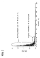
- Fig. 7 provides a graph illustrating a frequency study of the variations in correction axle shaft torque provided by the motor generator 2.
- the frequency strength distribution is highly intensive in a region of frequencies less than or equal to 1 Hz, with most frequencies concentrated in a region less than or equal to 4Hz. For this reason, the region that is necessary for frequency response of the motor generator 2 is conceivably at approximately 4Hz or less.
- a performance at 5 to 10 times the required frequency is sufficient as the frequency response of the motor generator 2.
- the motor generator 2 can sufficiently regulate the correction axle shaft torque in this embodiment.
- the vehicle stability control system of this embodiment can suppress the pitching vibration. This makes it possible to prevent the stability of the vehicle from being disturbed due to the pitching vibration, thus realizing stabilized running of the vehicle.
- the vibrational energy is removed in this manner, thereby making it possible to adjust the engine energy to a better value of efficiency, as well as to improve fuel efficiency. Still further, the excessive energy can be used for generating electric power, thereby allowing the electric energy to be utilized efficiently.
- the aforementioned embodiment uses the motor generator 2 as the engine load device, in which the motor generator 2 is used as a motor and a generator, thereby addressing both the cases where the corrected physical quantity corresponding to the pitching vibration is positive and negative.
- the motor generator 2 is only one example of the engine load device; other load devices, such as one including a starter and an alternator may also be employed. In this case, the combination of the starter and the alternator could also address both the cases where the corrected physical quantity corresponding to the pitching vibration is positive and negative.
- the aforementioned embodiment allows the engine ECU 3 to determine the instruction signal for the motor generator 2; however, other aspects of the system other than the engine ECU 3 may also employed.
- the required drive force is calculated generally in the engine ECU 3, it is also possible to obtain the torque used for acceleration and deceleration of the vehicle from a calculation result provided by the engine ECU 3.
- the aforementioned embodiment directly determines a physical quantity, which is the axle shaft torque corresponding to the drive force, in order to remove the pitching vibrational energy.
- a physical quantity which is the axle shaft torque corresponding to the drive force
- other physical quantities may also be employed, or a converted physical quantity corresponding to the axle shaft torque may be employed to carry out each of the aforementioned calculations.
- Such a vibration may include a rolling vibration of the vehicle, a vertical vibration of the vehicle, a vertical vibration of the engine, and a slant angle vibration of the engine.
Landscapes
- Engineering & Computer Science (AREA)
- Chemical & Material Sciences (AREA)
- Combustion & Propulsion (AREA)
- Transportation (AREA)
- Mechanical Engineering (AREA)
- Electric Propulsion And Braking For Vehicles (AREA)
- Hybrid Electric Vehicles (AREA)
- Control Of Vehicle Engines Or Engines For Specific Uses (AREA)
- Vibration Prevention Devices (AREA)
- Control Of Throttle Valves Provided In The Intake System Or In The Exhaust System (AREA)
Abstract
Description
- The present invention relates to a vehicle stability control system for suppressing vibrations generated during running of a vehicle.
- Conventionally, a regenerative brake is known which is designed to produce braking force using a braking apparatus as well as an engine load apparatus, such as an alternator, during braking of the vehicle. An example of such a system is disclosed in Japanese Patent Laid-Open Publication No. Hei 10-285706. The regenerative brake actively turns on an engine load, such as an alternator, during braking of the vehicle in order to absorb kinetic energy of the vehicle, thereby supplementing the braking capability of the braking apparatus.
- While the vehicle is running, there are various factors that may disturb the stability of the vehicle. One of the factors includes the fact that more kinetic energy may be produced than is required for the vehicle to run. Conversely, an insufficient amount of kinetic energy may be produced. For example, assuming that the vehicle body is maintained horizontally when in a stable state, a squat may occur which causes the front of the vehicle to displace upward from the stable state due to an excessive drive torque. Additionally, a nosedive may occur which causes the front of the vehicle to displace downward from the stable state due to a drive torque reactive force generated during braking. The squat and the nosedive result from kinetic energy that is produced beyond that which is required for the vehicle to run.
- The aforementioned conventional regenerative brake is designed to impose a load on the engine to supplement the braking capability of the braking apparatus. However, no brake currently exists that is designed to absorb excessive kinetic energy by activating the engine load in order to ensure the stability of the vehicle.
- The present invention was developed in view of the aforementioned and other problems. The principles of the present invention provide a vehicle stability control system and a method for offsetting vibrations generated during running of the vehicle. The system and the method are adapted to remove vibrations by establishing an engine load to absorb kinetic energy provided beyond that which is required or to supplement the engine power when the required kinetic energy cannot be obtained.
- The inventors of the present invention reviewed the energy that may disturb the stability of a vehicle. Fig. 8 shows various kinetic energies provided by a vehicle. As illustrated, the kinetic energies of the vehicle include the pitching rotational energy, the rolling rotational energy, and the yawing rotational energy. Also included are the translational energy in the X-direction (along which the vehicle travels), the translational energy in the Y-direction (or the lateral direction of the vehicle), and the translational energy in the Z-direction (or the vertical direction of the vehicle).
- These kinetic energies have a steady-state value with no vibrational components when the vehicle is in the stable state, and therefore, the inventors of the present invention studied the vibrational components, among other things, as the energy that may disturb the stability of the vehicle. The inventors found that the vibrational energy could always be absorbed, thereby effectively preventing the stability of the vehicle from being disturbed in order to keep the vehicle as close to the stable state at all times. This will be herein described in the context of the pitching vibration as an example; however, it should be appreciated that a similar discussion would be applicable to any other vibrational components.
- Here, the pitching vibrational energy refers to the rotational vibrational energy in the pitching direction. The pitching direction is defined as rotating about the vehicle axis in the lateral direction with the center of gravity of the vehicle as its center. The pitching vibrational energy results from a squat caused during acceleration, as shown in Fig. 9A. Additionally, a nosedive caused during deceleration may occur, as shown in Fig. 9B, or during turning, as shown in Fig. 9C.
- As shown in Fig. 9A, during acceleration, since the vehicle body cannot follow the rotation of the driving wheels, the nose of the vehicle rises about the center of gravity of the vehicle resulting in a squat. On the other hand, as shown in Fig. 9B, during deceleration, such as braking, since the vehicle body cannot follow the deceleration of the driving wheels due to inertia during application of braking force to the wheels, the nose of the vehicle lowers about the center of gravity of the vehicle resulting in a nosedive. Additionally, as shown in Fig. 9C, while the vehicle is turning, the occurrence of a cornering drag causes the driving wheels to decelerate, thus, resulting in a nosedive similar to that depicted in Fig. 9B.
- The rotational vibrations about the center of gravity of the vehicle, such as the squat and nosedive described above, are pitching vibrations. These are pitching vibrational energies or excessive energies that disturb the stability of the vehicle. In other words, an excessive energy provided externally induces the pitching vibration resulting in the pitching vibrational energy. Such pitching vibrational energy occurs almost continuously while the vehicle is running. It can thus be said that the stability of the vehicle can be effectively maintained by suppressing such pitching vibration.
- In this context, one aspect of the present invention provides a vehicle stability control system which uses a physical quantity corresponding to a driver accelerator input to control engine power produced by an engine, as well as to controllably drive an engine load for regulating the engine power, thereby producing a desired drive force. The vehicle stability control system includes vibration detection means for determining a vibration during running of the vehicle. The system also includes correction means for driving the engine load to suppress the vibration in response to the vibration determined by the vibration detection means.
- As described above, the system drives the engine load in response to the vibration that disturbs the stability of the vehicle. The engine load suppresses the vibration. This makes it possible to prevent the stability of the vehicle from being disturbed due to the vibration.
- In another aspect of the present invention, the vibration detection means can determine a vehicle body input torque and estimate the vibration based on the vehicle body input torque. More specifically, in another aspect of the present invention, the vibration detection means can detect the vibration corresponding to the vehicle body input torque in accordance with an on-spring vehicle body vibration model developed in view of the vibration of the on-spring vehicle body itself that is supported by the front and rear wheel suspensions of the vehicle.
- In still another aspect of the present invention, in the case where the engine load is produced by a motor generator that serves as a motor and a generator, the system determines an appropriate axle shaft torque proportion between the engine and the motor generator to produce a desired axle shaft torque. The proportion is based on a physical quantity corresponding to the driver accelerator input. In accordance with the proportion thus determined, the system then allows the motor generator to serve as a motor or a generator or stop. In this arrangement, the correction means can thus correct the vibration-based physical quantity determined by the vibration detection means to obtain a physical quantity corresponding to the amount of drive force allocated to the motor generator, thereby making it possible to suppress the vibration.
- In this arrangement and in accordance with yet another aspect of the present invention, when the corrected vibration-based physical quantity provided in accordance with the axle shaft torque proportion is negative in the case of using the motor generator as a motor, the correction means can subtract the physical quantity corresponding to the vibration from a physical quantity corresponding to a drive force generated by the motor to take the resulting physical quantity as a physical quantity corresponding to the proportion of the post-correction drive force for the motor generator. On the other hand, when the corrected vibration-based physical quantity is positive in the case of using the motor generator as a generator, the correction means can subtract the physical quantity corresponding to the vibration from a physical quantity corresponding to a drive force reduced by the generator to take the resulting physical quantity as a physical quantity corresponding to the proportion of the post-correction drive force for the motor generator.
- A still further aspect of the present invention supposes that the engine load is a starter or an alternator. In this arrangement, when the corrected vibration-based physical quantity is negative, the correction means outputs the vibration-based physical quantity as an instruction signal for driving the alternator. When the vibration-based physical quantity is positive, the correction means outputs the vibration-based physical quantity as an instruction signal for driving the starter.
- According to a still further aspect of the present invention, the aforementioned vibration that disturbs the stability of the vehicle may be, for example, either one of the pitching vibration, the rolling, and the vertically displaced vibration of the vehicle body, and the vertical vibration and the slant angle vibration of the engine.
- Other features and advantages of the present invention will be appreciated, as well as methods of operation and the function of the related parts from a study of the following detailed description, appended claims, and drawings, all of which form a part of this application. In the drawings:
- Fig. 1 is a schematic view of a vehicle stability control system according to a first embodiment of the present invention adapted to a vehicle;
- Fig. 2 is a block diagram of an engine electronic control unit of the vehicle stability control system shown in Fig. 1;
- Fig. 3 is a schematic diagram of a pitching vibration suppression corrective portion of the engine electronic control unit of Fig. 2;
- Fig. 4 is a side view of a on-spring vibration model of a vehicle;
- Fig. 5 is a timing chart of vehicle speed and accelerator opening when a vehicle equipped with the vehicle stability control system of Fig. 1 is running on a highway;
- Fig. 6 is a timing chart of a corrective torque produced by a motor generator when a vehicle equipped with the vehicle stability control system of Fig. 1 is running on a highway;
- Fig. 7 is a graph illustrating a frequency distribution of variations in corrective torque produced by the motor generator associated with Fig. 6;
- Fig. 8 is an isometric view of a vehicle illustrating various vibrational energies; and
- Figs. 9A-9C are side views of a vehicle in a squat position due to acceleration, a nosedive position due to deceleration, and a nosedive position due to turning, respectively.
- Now, an explanation will be given to a vehicle stability control system according to a first embodiment of the present invention. This embodiment shows an example in which the vehicle stability control system is adapted to a vehicle, such as a hybrid vehicle, which has a motor generator. Fig. 1 schematically shows the configuration of the vehicle stability control system according to this embodiment. In this embodiment, a rear-wheel drive vehicle is used for explanatory purposes; however, the present invention is also applicable to a front-wheel drive vehicle or a four-wheel drive vehicle.
- The vehicle stability control system according to this embodiment is configured to suppress a vibration, which may disturb the stability of the vehicle, by regulating the drive torque generated by an
engine 1 included in the vehicle using amotor generator 2 serving as an engine load device to establish an engine load. Here, the description is given to an example in which the pitching vibration is suppressed. - In the vehicle stability control system shown in Fig. 1, the
engine 1 and themotor generator 2 are controlled by anengine ECU 3. Fig. 2 schematically shows the configuration of theengine ECU 3 in a block diagram. - As shown in Fig. 2, the
engine ECU 3 includes a required drive forcecomputational portion 3a, a pitching vibration suppressioncorrective portion 3b, and an actuator instructioncomputational portion 3c. - A detected signal corresponding to the amount of operation of an
accelerator pedal 4 is delivered from apedal stroke sensor 5 as a physical quantity corresponding to the driver accelerator input. In this case, the required drive forcecomputational portion 3a determines the amount of operation of theaccelerator pedal 4 based on the detected signal, and determines the required axle shaft torque serving as a required drive force corresponding to the amount of operation. The drive torque required by the driver, as determined here, is to be the torque used in accelerating and decelerating the vehicle and is referred to as the required axle shaft torque. - The required drive force
computational portion 3a is adapted to determine the required axle shaft torque. The required axle shaft torque is a total sum of the axle shaft torque generated by theengine 1 and the axle shaft torque generated by themotor generator 2. The required drive forcecomputational portion 3a also determines the proportional between the axle shaft torques of theengine 1 and themotor generator 2 to improve the engine efficiency in response to the running condition of the vehicle. The computation or the like of the required axle shaft torque is well known in the field of engine control for a hybrid vehicle and thus, will not be detailed herein. - Once the required axle shaft torque and its proportion are determined, the required drive force
computational portion 3a delivers an instructional signal to theengine 1 and themotor generator 2 in order to allow theengine 1 and themotor generator 2 to produce the axle shaft torque in accordance with their respective proportions. - This allows the amount of intake air and the amount of injected fuel for the
engine 1 to be regulated, so that energy is delivered according to the proportion. Then, the energy is transmitted as rotational energy to adriving wheel 8 via a transmission (T/M) 6 and afinal reduction gear 7 to generate the axle shaft torque in thedriving wheel 8 as required. - Additionally, the proportion of the axle shaft torque to be generated by the
motor generator 2, as determined in this manner, also serves to determine how themotor generator 2 should be actuated. - Now, the
motor generator 2 will be described. Themotor generator 2 serves as a motor as well as a generator. Generally, in a hybrid vehicle, themotor generator 2 serves as a motor in a region where the engine has bad efficiency, such as when the vehicle is accelerated from rest. On the other hand, themotor generator 2 stops in a region where the engine has good efficiency, such as when the vehicle is running at an intermittent or low speed load. Finally, themotor generator 2 serves as a generator when the accelerator is released such as during deceleration and braking. - Accordingly, once the instruction signal is delivered to the
motor generator 2, themotor generator 2 serves as either a motor or a generator, or stops without serving as either in accordance with its proportion of the axle shaft torque. When serving as a motor, themotor generator 2 produces a positive axle shaft torque to increase the axle shaft torque supplied to the drive wheels. When serving as a generator, themotor generator 2 produces a negative axle shaft torque to decrease the axle shaft torque supplied to the drive wheels. At a standstill, themotor generator 2 is not to produce the axle shaft torque by itself. Accordingly, themotor generator 2 serves as a motor when the drive torque proportion requires a positive axle shaft torque; serves as a generator when a negative axle shaft torque is required; and is brought into a standstill when nothing is required. - As described above, after the proportion of the drive torque to be produced by each of the
engine 1 and themotor generator 2 has been determined, the pitching vibration suppressioncorrective portion 3b corrects the drive torque allocated to themotor generator 2. The pitching vibration suppressioncorrective portion 3b corresponds to the vibration detection means and the correction means referred to herein. - As described above, the hybrid vehicle determines the drive torque proportion between the
engine 1 and themotor generator 2 to provide improved engine efficiency, in which the pitching vibrational energy is included. It is thus necessary to correct the drive torque of themotor generator 2 so that the pitching vibration can be suppressed. For example, when more engine energy has been produced than is necessary and the corrected value (corrected physical quantity) corresponding to the pitching vibration is positive, it is necessary to use themotor generator 2 as a generator to thereby remove the pitching vibration. On the other hand, when less engine energy is provided than is necessary and the corrected value corresponding to the pitching vibration is negative, it is necessary to use themotor generator 2 as a motor to supplement the engine energy to remove the pitching vibration. - The pitching vibration suppression
corrective portion 3b performs such a correction. More specifically, the pitching vibration suppressioncorrective portion 3b determines a vehicle body input torque based on a detected signal, such as from asensor 9 for sensing the amount of intake air or a current sensor of themotor generator 2. The pitching vibration suppressioncorrective portion 3b then determines the possible pitching vibration in accordance with the vehicle body input torque and delivers an instruction signal for driving themotor generator 2 in order to suppress the pitching vibration. - In the hybrid vehicle, the
engine ECU 3 uses themotor generator 2 as a motor or a generator to improve overall energy efficiency. Accordingly, suppose that themotor generator 2 is used as a motor in a region where the engine efficiency is bad. In this case, when the corrected value corresponding to the pitching vibration is positive, as described above, the required drive forcecomputational portion 3a receives an instruction signal indicative of a motor output from which the corrected value corresponding to the pitching vibration has been subtracted. In contrast to this, suppose that themotor generator 2 is used as a generator during braking. In this case, when the corrected value corresponding to the pitching vibration is negative, as described above, the required drive forcecomputational portion 3a receives an instruction signal indicative of a generator output from which the corrected value corresponding to the pitching vibration has been subtracted. - Now, the pitching vibration suppression
corrective portion 3b will be described in detail with reference to Fig. 3. - Fig. 3 shows a schematic diagram of the pitching vibration suppression
corrective portion 3b. As illustrated in the figure, the pitching vibration suppressioncorrective portion 3b uses an on-spring vibration model to determine the pitching vibrational energy from the vehicle body input torque that is determined, such as from the detected signal provided by an intake-air quantity sensor 9. The pitching vibration suppressioncorrective portion 3b then determines the torque required to remove the pitching vibrational energy. - In this embodiment, the on-spring vibration model is defined as will be explained below. Now, the on-spring vibration model is explained with reference to a schematic view of the on-spring vibration model shown in Fig. 4.
- This on-spring vibration model relies on whether the on-spring portion would be subjected to a total torque reaction Tr at a driving wheel speed of ωw to be vibrated about the pitching center. Here, the on-spring vibration is modeled on the assumption that the vehicle body is considered to be a flat plate on an arbitrary horizontally-parallel reference plane, with the tires being suspended by a suspension and the
engine 1 or the like being mounted on the flat plate. - In the on-spring vibration model, each of the constants is defined as follows. First, for each front and rear driving wheel mounted on the reference plane, defined are suspension spring constants Kf and Kr, suspension damping coefficients Cf and Cr, the weight m of the
engine 1, and the spring constant Ke and the damping coefficient Ce of the engine mount. - Also defined are the radius r of the tires, the vehicle body mass M(kg) on the spring, the mass m(kg) of the
engine 1 and the T/M 6 combined, the wheel base L(m), and the distance Lfo(m) between the center of gravity of the vehicle and the front axle shaft. Further defined are the distance Lro(m) between the center of gravity of the vehicle and the rear axle shaft, as well as the distance Le between the center of gravity of the vehicle and the center of the mass of theengine 1 and the T/M 6. Still further defined is the distance hc(m) between the the height of the reference plane serving as the vehicle body reference line and the height of the center of gravity of the vehicle. - Also defined is the pitching inertial moment Ip(kgm2) of the vehicle body and the gravitational acceleration g(m/s2).
- On the other hand, for independent variables, defined are the vertical displacement x(m) of the vehicle body on the spring, the vertical displacement xe of the
engine 1 and the T/M 6, and the pitch angle θp (rad) about a virtual pitching center. - First, the virtual pitch angle about the pitching center is expressed by θP. Accordingly, the amount of displacement about the pitch center of the front axle shaft spaced apart by Lfo from the pitching center is expressed by LfθP, and the amount of displacement about the pitch center of the rear axle shaft spaced apart by Lro from the pitching center is expressed by LrθP.
- Therefore, an equation of the motion about the pitch center of the vehicle body is expressed as in
Equation 1 provided below.
- The equations of vertical motion of the vehicle body and of the
engine 1 and the T/M 6 are expressed inEquations 

- Xe", x", and θp" are determined from
Equations 1 to 3 to giveEquations 4 to 6, respectively provided below.


- Therefore, assuming that each state quantity is defined such that xe=x1, xe'=x2, x=x3, x'=x4, θp=x5, θp'=x6, and input u =ΔTr; coefficients of the variables in each of the aforementioned equations are defined to be a1 to a6, b1 to b6, c1 to c6, and p1, thereby each of the aforementioned equations are transformed as follows:


- In the
aforementioned Equations 7 to 9, it is defined such that a1 = - Ke/m, a2 = -Ce/m, a3 = Ke/m, a4 = Ce/m, a5 = KeLe/m, a6 = CeLe/m, b1 = Ke/M, b2 = Ce/M, b3 = -(Ke + Kf + Kr)/M, b4 = -(Ce + Cf + Cr)/M, b5 = -(KfLf + KeLe - KrLr)/M, b6 = -(CfLf + CeLe - CrLr)/Mc1 = KeLe/Ip, c2 = CeLe/Ip, c3 = -(KfLf + KeLe - KrLr)/Ip, c4 = -(CfLf + CeLe - CrLr)/Ip, c5 = -(KfLf2 + KeLe2 + KrLr2 - hcMg)/Ip, c6 = -(CfLf2 + CeLe2 + CrLr2)/Ip, and p1 = (1 + hc/r)/Ip. - Since x1 to x6 have been defined above, the following relations hold true:


- Therefore, the equations of state of the state space representations shown by
Equations 10 to 15 are expressed as inEquation 16 provided below.
-
Equation 16 is the equation of state of the on-spring vibration model with x'= Ax + Bu shown in Fig. 4. - This equation of state is used to calculate the amount of correction for suppressing the pitching vibration. In the calculation, a known technique, such as a technique for designing an optimized regulator, may be used to determine the state feedback gain K. However, the technique will not be detailed herein.
- The ΔTr is determined in this manner, and then multiplied by KDiff. The resulting value is subtracted from the
motor generator 2 proportion of the axle shaft torque determined previously by the required drive forcecomputational portion 3a, thereby providing a computed post-correction required drive force. That is, themotor generator 2 proportion of axle shaft torque determined by the required drive forcecomputational portion 3a is the axle shaft torque to be used for acceleration and deceleration. The axle shaft torque determined by the pitching vibration suppressioncorrective portion 3b is the axle shaft torque corresponding to the corrected value for the pitching vibration. Accordingly, the corrected value of torque is subtracted from the axle shaft torque to be used for acceleration and deceleration, thereby allowing for the determination of the post-correction required axle shaft torque corresponding to the post-correction drive force to which a correction is made using the corrected value corresponding to the pitching vibration. - Here, K is a designed value, which is defined in accordance with the aforementioned independent variables or constants, while KDiff is a value to be determined by the gear ratio of the
final reduction gear 7. - To produce the post-correction required axle shaft torque determined by the pitching vibration suppression
corrective portion 3b, the actuator instructioncomputational portion 3c delivers to themotor generator 2 an instruction signal corresponding with the post-correction required axle shaft torque. In accordance with the instruction signal, themotor generator 2 will serve as either a motor or a generator, or stop, thereby generating the post-correction required axle shaft torque. - In the aforementioned arrangement, each portion of the
ECU 3 performed the aforementioned computations to control theengine 1 and themotor generator 2, the experimental results of which are shown in Figs. 5 and 6. Figs. 5 and 6 show actual running data on a vehicle, running on a highway and equipped with the vehicle stability control system of this embodiment. Fig. 5 shows the vehicle speed and the accelerator opening in the form of a timing chart. Fig. 6 shows, in the form of a timing chart, the correction torque provided by themotor generator 2 with the same timing as in Fig. 5. - Assuming that changes in accelerator opening result in changes of vehicle speed, as represented in Fig. 5, the correction axle shaft torque provided by the
motor generator 2 varies, as shown in Fig. 6. As shown in the figure, when more engine energy is produced than is necessary resulting in a pitching vibration, the axle shaft torque for absorbing the excessive energy is the correction axle shaft torque. When less engine energy is produced than is necessary resulting in a pitching vibration, the axle shaft torque for supplementing the lack of energy is the correction axle shaft torque. - Accordingly, the
motor generator 2 can be used as a motor or a generator to regulate the engine energy, thereby removing the pitching vibration. This makes it possible to prevent the stability of the vehicle from being disturbed due to the pitching vibration, thus realizing stabilized running of the vehicle. - Fig. 7 provides a graph illustrating a frequency study of the variations in correction axle shaft torque provided by the
motor generator 2. As shown in this figure, it can be seen that the frequency strength distribution is highly intensive in a region of frequencies less than or equal to 1 Hz, with most frequencies concentrated in a region less than or equal to 4Hz. For this reason, the region that is necessary for frequency response of themotor generator 2 is conceivably at approximately 4Hz or less. To neglect the transient response of themotor generator 2, a performance at 5 to 10 times the required frequency is sufficient as the frequency response of themotor generator 2. For example, with a frequency response of about 20Hz, themotor generator 2 can sufficiently regulate the correction axle shaft torque in this embodiment. - As described above, the vehicle stability control system of this embodiment can suppress the pitching vibration. This makes it possible to prevent the stability of the vehicle from being disturbed due to the pitching vibration, thus realizing stabilized running of the vehicle.
- Furthermore, the vibrational energy is removed in this manner, thereby making it possible to adjust the engine energy to a better value of efficiency, as well as to improve fuel efficiency. Still further, the excessive energy can be used for generating electric power, thereby allowing the electric energy to be utilized efficiently.
- The aforementioned embodiment uses the
motor generator 2 as the engine load device, in which themotor generator 2 is used as a motor and a generator, thereby addressing both the cases where the corrected physical quantity corresponding to the pitching vibration is positive and negative. However, themotor generator 2 is only one example of the engine load device; other load devices, such as one including a starter and an alternator may also be employed. In this case, the combination of the starter and the alternator could also address both the cases where the corrected physical quantity corresponding to the pitching vibration is positive and negative. - Furthermore, the aforementioned embodiment allows the
engine ECU 3 to determine the instruction signal for themotor generator 2; however, other aspects of the system other than theengine ECU 3 may also employed. In this case, since the required drive force is calculated generally in theengine ECU 3, it is also possible to obtain the torque used for acceleration and deceleration of the vehicle from a calculation result provided by theengine ECU 3. - Furthermore, the aforementioned embodiment allocatesthe axle shaft torque corresponding to the drive force to the
engine 1 and themotor generator 2, and thereafter makes a correction to suppress the pitching vibration. However, the present invention is also applicable to an arrangement in which a correction to suppress the pitching vibration is first made to the drive force, which is then allocated between theengine 1 and themotor generator 2. - Still further, the aforementioned embodiment directly determines a physical quantity, which is the axle shaft torque corresponding to the drive force, in order to remove the pitching vibrational energy. However, other physical quantities may also be employed, or a converted physical quantity corresponding to the axle shaft torque may be employed to carry out each of the aforementioned calculations.
- Furthermore, the aforementioned embodiment has been described in accordance with an example of pitching vibration employed as a vibration that disturbs the stability of the vehicle; however, the same method is also applicable to other vibrational energies. Such a vibration may include a rolling vibration of the vehicle, a vertical vibration of the vehicle, a vertical vibration of the engine, and a slant angle vibration of the engine.
Claims (9)
- A vehicle stability control system that uses a physical quantity corresponding to a driver accelerator input to control engine power produced by an engine (1) and to controllably drive an engine load device (2) for regulating the engine power, thereby producing a desired drive force, the vehicle stability control system comprising:vibration detection means (3) for determining a vibration which occurs during running of the vehicle to disturb the stability of the vehicle; andcorrection means (3) for driving the engine load device (2) to suppress the vibration in response to the vibration determined by the vibration detection means (3).
- The vehicle stability control system according to claim 1, wherein the vibration detection means (3) determines a vehicle body input torque and estimates the vibration based on the vehicle body input torque.
- The vehicle stability control system according to claim 2, wherein the vibration detection means (3) detects the vibration corresponding to the vehicle body input torque in accordance with an on-spring vehicle body vibration model developed based on the vibration of the on-spring vehicle body itself that is supported by front and rear wheel suspensions of the vehicle.
- The vehicle stability control system according to any one of claims 1 to 3, wherein
the engine load device (2) is a motor generator that serves as a motor and a generator, and
the system determines a drive force proportion between the engine (1) and the motor generator (2) based on a physical quantity corresponding to a driver accelerator input to produce the desired drive force, and in accordance with the proportion thus determined, the system then allows the motor generator (2) to serve as a motor or a generator or stop; and
the correction means (3) corrects a vibration-based physical quantity for correction determined by the vibration detection means (3) to obtain a physical quantity corresponding to the proportion of drive force for the motor generator (2), thereby making it possible to suppress the vibration. - The vehicle stability control system according to claim 4, wherein when the corrected vibration-based physical quantity provided in accordance with the drive force proportion is negative in the case of using the motor generator (2) as a motor, the correction means (3) subtracts the physical quantity corresponding with the vibration from a physical quantity corresponding with a drive force generated by the motor to take the resulting physical quantity as a physical quantity corresponding to the proportion of the post-correction drive force for the motor generator (2), and
when the corrected vibration-based physical quantity is positive in the case of using the motor generator (2) as a generator, the correction means (3) subtracts the physical quantity corresponding with the vibration from a physical quantity corresponding with a drive force reduced by the generator to take the resulting physical quantity as a physical quantity corresponding to the proportion of the post-correction drive force for the motor generator (2). - The vehicle stability control system according to any one of claims 1 to 3, wherein
the engine load device (2) includes a starter and an alternator, and
when a corrected vibration-based physical quantity is negative, the correction means (3) outputs the vibration-based physical quantity as an instruction signal for driving the alternator (2), and
when the vibration-based physical quantity is positive, the correction means (3) outputs the vibration-based physical quantity as an instruction signal for driving the starter (2). - The vehicle stability control system according to any one of claims 1 to 3, wherein
the engine load device (2) is a starter, and
when a corrected vibration-based physical quantity is positive, the correction means (3) outputs the vibration-based physical quantity as an instruction signal for driving the starter (2). - The vehicle stability control system according to any one of claims 1 to 3, wherein
the engine load device (2) is an alternator, and
when a corrected vibration-based physical quantity is negative, the correction means (3) outputs the vibration-based physical quantity as an instruction signal for driving the alternator (2). - The vehicle stability control system according to any one of claims 1 to 8, wherein the vibration detection means (3) detects, as the vibration that disturbs the stability of the vehicle, at least one of a pitching vibration, a rolling, and a vertically displaced vibration of a vehicle body, and a vertical vibration and a slant angle vibration of the engine (1).
Applications Claiming Priority (1)
| Application Number | Priority Date | Filing Date | Title |
|---|---|---|---|
| JP2004241009A JP2006060936A (en) | 2004-08-20 | 2004-08-20 | Vehicle behavior control system |
Publications (2)
| Publication Number | Publication Date |
|---|---|
| EP1637388A2 true EP1637388A2 (en) | 2006-03-22 |
| EP1637388A3 EP1637388A3 (en) | 2009-08-26 |
Family
ID=35462106
Family Applications (1)
| Application Number | Title | Priority Date | Filing Date |
|---|---|---|---|
| EP05017427A Withdrawn EP1637388A3 (en) | 2004-08-20 | 2005-08-10 | Vehicle stability control system |
Country Status (4)
| Country | Link |
|---|---|
| US (1) | US7783402B2 (en) |
| EP (1) | EP1637388A3 (en) |
| JP (1) | JP2006060936A (en) |
| CN (1) | CN100400330C (en) |
Cited By (2)
| Publication number | Priority date | Publication date | Assignee | Title |
|---|---|---|---|---|
| WO2010131091A3 (en) * | 2009-05-13 | 2011-05-12 | Toyota Jidosha Kabushiki Kaisha | Sprung mass damping control system of vehicle |
| EP2557011A4 (en) * | 2010-03-25 | 2018-04-18 | Mitsubishi Nichiyu Forklift Co., Ltd. | Industrial vehicle |
Families Citing this family (35)
| Publication number | Priority date | Publication date | Assignee | Title |
|---|---|---|---|---|
| JP4606350B2 (en) * | 2006-03-09 | 2011-01-05 | 国立大学法人長岡技術科学大学 | Electric vehicle tangential force estimation method |
| JP4685731B2 (en) * | 2006-08-28 | 2011-05-18 | 日立オートモティブシステムズ株式会社 | MOBILE BODY DIAGNOSIS DEVICE, MOBILE BODY DIAGNOSIS TERMINAL, AND INVERTER DEVICE |
| US20100094495A1 (en) * | 2007-03-05 | 2010-04-15 | Yokohama National University | Pitching control device of motor vehicle and control method |
| JP4396717B2 (en) | 2007-03-07 | 2010-01-13 | トヨタ自動車株式会社 | Vehicle control apparatus, control method, program for realizing the method, and recording medium recording the program |
| JP4910794B2 (en) * | 2007-03-12 | 2012-04-04 | トヨタ自動車株式会社 | Drive control device for controlling vibration control of vehicle |
| US8161843B2 (en) * | 2007-08-21 | 2012-04-24 | Florida State University Research Foundation | Damping motor and control approach for mitigating torsional backlash, damping critical geartrain speeds, and providing improved torque control in mechanical gears |
| US7997363B2 (en) | 2007-09-17 | 2011-08-16 | Denso Corporation | Vehicle control system and method |
| US8322728B2 (en) | 2007-09-28 | 2012-12-04 | Hitachi, Ltd. | Suspension control apparatus |
| JP4872884B2 (en) * | 2007-11-01 | 2012-02-08 | トヨタ自動車株式会社 | Diesel engine vehicle vibration control system |
| JP4650483B2 (en) | 2007-12-12 | 2011-03-16 | 株式会社デンソー | Vehicle travel control device |
| WO2010050070A1 (en) * | 2008-10-31 | 2010-05-06 | トヨタ自動車株式会社 | Damping controller of vehicle |
| JP4938809B2 (en) * | 2009-01-27 | 2012-05-23 | 本田技研工業株式会社 | Vehicle driving force control device |
| JP5152014B2 (en) * | 2009-01-29 | 2013-02-27 | トヨタ自動車株式会社 | Vehicle drive torque control device |
| JP5347702B2 (en) * | 2009-05-13 | 2013-11-20 | トヨタ自動車株式会社 | Vehicle sprung mass damping control device |
| JP5287559B2 (en) * | 2009-07-09 | 2013-09-11 | トヨタ自動車株式会社 | Vehicle vibration control device |
| JP4978722B2 (en) * | 2010-08-23 | 2012-07-18 | 株式会社デンソー | Speed control device |
| US20120150376A1 (en) * | 2010-12-14 | 2012-06-14 | Amp Electric Vehicles Inc. | Independent control of drive and non-drive wheels in electric vehicles |
| WO2012147164A1 (en) | 2011-04-26 | 2012-11-01 | トヨタ自動車株式会社 | Vehicle control device |
| JP5556779B2 (en) | 2011-09-28 | 2014-07-23 | 株式会社デンソー | Vehicle control device |
| KR20130055472A (en) * | 2011-11-18 | 2013-05-28 | 현대자동차주식회사 | Vibration controling system of power train for vehicle and controlling method thereof |
| JP6010985B2 (en) * | 2012-04-06 | 2016-10-19 | 日産自動車株式会社 | Vehicle system vibration control device |
| DE102012206559A1 (en) * | 2012-04-20 | 2013-10-24 | Bayerische Motoren Werke Aktiengesellschaft | Device for rotating Drehunförmigkeiten a drive train of a hybrid vehicle |
| US9356548B2 (en) | 2012-05-10 | 2016-05-31 | Denso Corporation | Vibration damping control apparatus for vehicle, vibration damping control system for vehicle, and vehicle motion control apparatus |
| JP5609998B2 (en) * | 2012-05-10 | 2014-10-22 | 株式会社デンソー | Vehicle damping control device and vehicle damping control system |
| CN102979636B (en) * | 2012-12-21 | 2015-07-29 | 潍柴动力股份有限公司 | A kind of method and device reducing power assembly system vibration under idling operation |
| US9481256B2 (en) | 2014-01-30 | 2016-11-01 | Amp Electric Vehicles Inc. | Onboard generator drive system for electric vehicles |
| JP6481329B2 (en) * | 2014-10-28 | 2019-03-13 | トヨタ自動車株式会社 | Sprung vibration suppression device for vehicle |
| JP2016211478A (en) * | 2015-05-12 | 2016-12-15 | スズキ株式会社 | Vehicle control device |
| JP6536543B2 (en) * | 2016-11-17 | 2019-07-03 | トヨタ自動車株式会社 | Vehicle control device |
| JP6702201B2 (en) * | 2017-01-18 | 2020-05-27 | トヨタ自動車株式会社 | Vehicle drive control device |
| CN108327505B (en) * | 2017-01-20 | 2020-01-03 | 比亚迪股份有限公司 | Automobile and active vibration damping control method and device thereof |
| DE102017202750A1 (en) * | 2017-02-21 | 2018-08-23 | Volkswagen Aktiengesellschaft | Control system and method for damping vibrations of a drive train of a motor vehicle and motor vehicle with such a control system |
| US11859571B2 (en) * | 2021-07-21 | 2024-01-02 | Ford Global Technologies, Llc | Methods for a road surface metric |
| JP2023068985A (en) * | 2021-11-04 | 2023-05-18 | ヤマハ発動機株式会社 | vehicle |
| CN119582661B (en) * | 2025-02-06 | 2025-06-03 | 泰州学院 | Intelligent micro turbine power generation control system suitable for different flying heights |
Citations (1)
| Publication number | Priority date | Publication date | Assignee | Title |
|---|---|---|---|---|
| JPH10285706A (en) | 1997-03-31 | 1998-10-23 | Nissan Diesel Motor Co Ltd | Device for regenerating deceleration energy of vehicle |
Family Cites Families (33)
| Publication number | Priority date | Publication date | Assignee | Title |
|---|---|---|---|---|
| US4728120A (en) * | 1985-10-03 | 1988-03-01 | Toyota Jidosha Kabushiki Kaisha | Suspension controller |
| JP2574761B2 (en) | 1986-05-23 | 1997-01-22 | 株式会社日立製作所 | Vehicle suspension control method |
| JPH0734678B2 (en) * | 1989-11-09 | 1995-04-12 | いすゞ自動車株式会社 | Idle vibration reduction device |
| JP3733929B2 (en) | 1992-02-17 | 2006-01-11 | 株式会社日立製作所 | Motor and vehicle motion control device |
| EP0557034B1 (en) | 1992-02-17 | 1998-10-07 | Hitachi, Ltd. | A sensor for deriving a value of differential of acceleration. |
| JPH08216698A (en) | 1995-02-17 | 1996-08-27 | Toyota Motor Corp | Vehicle engine suspension system |
| JP2002515962A (en) * | 1995-08-31 | 2002-05-28 | イーエスアーデー・エレクトロニク・ジステームス・ゲーエムベーハー・ウント・コンパニ・カーゲー | Mechanism for positively reducing radial vibrations of a rotating shaft and a method suitable therefor |
| KR100192954B1 (en) * | 1996-07-18 | 1999-06-15 | 김광호 | Image pick-up device with a vertical transmission gate |
| DE19721298C2 (en) | 1997-05-21 | 2001-09-06 | Mannesmann Sachs Ag | Hybrid travel drive for a motor vehicle |
| WO1999028172A1 (en) * | 1997-11-28 | 1999-06-10 | Denso Corporation | Vehicle controller |
| US6002974A (en) * | 1998-02-06 | 1999-12-14 | Delco Electronics Corporation | Vehicle rollover sensing using extended kalman filter |
| JPH11311297A (en) | 1998-04-24 | 1999-11-09 | Nissan Motor Co Ltd | Internal combustion engine vibration reduction device |
| JP2000217209A (en) * | 1999-01-22 | 2000-08-04 | Toyota Motor Corp | Vehicle damping device using electric motor as driving force source |
| JP2000224714A (en) * | 1999-02-03 | 2000-08-11 | Mitsubishi Motors Corp | Vehicle with electric motor |
| JP3841250B2 (en) | 1999-03-19 | 2006-11-01 | マツダ株式会社 | Vehicle travel control device |
| JP3642507B2 (en) | 1999-07-07 | 2005-04-27 | 本田技研工業株式会社 | Vehicle driving force control device |
| JP2001037006A (en) | 1999-07-14 | 2001-02-09 | Toyota Motor Corp | Vehicle damping device with multiple driving force sources |
| JP4480862B2 (en) * | 1999-09-07 | 2010-06-16 | 本田技研工業株式会社 | Control device for hybrid vehicle |
| JP3409755B2 (en) | 1999-11-01 | 2003-05-26 | トヨタ自動車株式会社 | Drive device vibration suppression device |
| JP2001132501A (en) * | 1999-11-08 | 2001-05-15 | Toyota Central Res & Dev Lab Inc | Vehicle drive system rotational vibration suppression device |
| JP3775562B2 (en) * | 2000-03-07 | 2006-05-17 | ジヤトコ株式会社 | Parallel hybrid vehicle |
| JP3983473B2 (en) * | 2000-12-14 | 2007-09-26 | トヨタ自動車株式会社 | Vibration control device for vehicle drive system vibration |
| JP3508742B2 (en) * | 2001-06-18 | 2004-03-22 | 日産自動車株式会社 | Vehicle vibration suppression control device using electric motor |
| JP3575479B2 (en) * | 2002-03-08 | 2004-10-13 | 日産自動車株式会社 | Vehicle driving force control device |
| US6842673B2 (en) * | 2002-06-05 | 2005-01-11 | Visteon Global Technologies, Inc. | Engine engagement control for a hybrid electric vehicle |
| KR20040002090A (en) * | 2002-06-29 | 2004-01-07 | 현대자동차주식회사 | Motor controlling apparatus for hybrid electric vehicle and method |
| US7110867B2 (en) * | 2002-08-26 | 2006-09-19 | Nissan Motor Co., Ltd. | Vibration suppression apparatus and method for hybrid vehicle |
| JP4356305B2 (en) | 2002-11-19 | 2009-11-04 | 株式会社デンソー | Vehicle control device |
| JP4078974B2 (en) * | 2002-12-26 | 2008-04-23 | トヨタ自動車株式会社 | Vehicle vibration suppression control |
| US6968261B2 (en) * | 2003-01-03 | 2005-11-22 | General Motors Corporation | Method and apparatus for vehicle stability enhancement system |
| US6856885B2 (en) * | 2003-04-01 | 2005-02-15 | General Motors Corporation | Vehicle stability enhancement control |
| US7232401B2 (en) * | 2004-01-28 | 2007-06-19 | General Motors Corporation | Method of compensating torque at cylinder switching on a DOD engine with electric parallel hybrid |
| US6976388B2 (en) * | 2004-05-14 | 2005-12-20 | General Motors Corporation | Diagnostic method for a torque control of an electrically variable transmission |
-
2004
- 2004-08-20 JP JP2004241009A patent/JP2006060936A/en active Pending
-
2005
- 2005-08-10 EP EP05017427A patent/EP1637388A3/en not_active Withdrawn
- 2005-08-11 US US11/201,489 patent/US7783402B2/en not_active Expired - Fee Related
- 2005-08-19 CN CNB2005100926701A patent/CN100400330C/en not_active Expired - Fee Related
Patent Citations (1)
| Publication number | Priority date | Publication date | Assignee | Title |
|---|---|---|---|---|
| JPH10285706A (en) | 1997-03-31 | 1998-10-23 | Nissan Diesel Motor Co Ltd | Device for regenerating deceleration energy of vehicle |
Cited By (4)
| Publication number | Priority date | Publication date | Assignee | Title |
|---|---|---|---|---|
| WO2010131091A3 (en) * | 2009-05-13 | 2011-05-12 | Toyota Jidosha Kabushiki Kaisha | Sprung mass damping control system of vehicle |
| RU2484992C1 (en) * | 2009-05-13 | 2013-06-20 | Тойота Дзидося Кабусики Кайся | Vehicle sprung mass damping control system |
| US8892280B2 (en) | 2009-05-13 | 2014-11-18 | Toyota Jidosha Kabushiki Kaisha | Sprung mass damping control system of vehicle |
| EP2557011A4 (en) * | 2010-03-25 | 2018-04-18 | Mitsubishi Nichiyu Forklift Co., Ltd. | Industrial vehicle |
Also Published As
| Publication number | Publication date |
|---|---|
| CN100400330C (en) | 2008-07-09 |
| JP2006060936A (en) | 2006-03-02 |
| EP1637388A3 (en) | 2009-08-26 |
| US20060041353A1 (en) | 2006-02-23 |
| CN1736756A (en) | 2006-02-22 |
| US7783402B2 (en) | 2010-08-24 |
Similar Documents
| Publication | Publication Date | Title |
|---|---|---|
| US7783402B2 (en) | Vehicle stability control system | |
| EP2429873B1 (en) | Sprung mass damping control system of vehicle, and vehicle provided with said system | |
| EP2778006B1 (en) | Vehicle behavior control device | |
| US8880292B2 (en) | Device for estimating vehicle body vibration and controller for suppressing vehicle body vibration using same | |
| EP1632382B1 (en) | Vehicle stability control system with running resistance fluctuation compensation | |
| KR101083946B1 (en) | Vehicle drive apparatus | |
| CN103079925B (en) | Vehicle body vibration damping control device | |
| US8510007B2 (en) | Vehicle motion control device | |
| CN109624947B (en) | Braking force control device for vehicle | |
| CN107010068B (en) | The driving-force control apparatus of vehicle | |
| US9008934B2 (en) | Braking-driving force control device of vehicle | |
| JP2009273275A (en) | Controller for vehicle | |
| WO2012023305A1 (en) | Automobile | |
| JP2012030760A (en) | Braking/driving force control device of vehicle | |
| JP2009273274A (en) | Controller for vehicle | |
| JP7809300B2 (en) | Design method and vehicle control device | |
| KR20230037177A (en) | Wheel slip control method for vehicle | |
| JP2006264628A (en) | Vehicle braking / driving force control device | |
| JP2007131212A (en) | Vehicle control device | |
| KR20130005867A (en) | Apparatus of controlling pitch motion for electric vehicles with in-wheel motor | |
| JP2010137724A (en) | Device and method for controlling vibration damping | |
| JP7754436B2 (en) | Vehicle control device and vehicle control method | |
| JP7788708B2 (en) | Vehicle control device and vehicle control method | |
| JP2010137722A (en) | Damping control device and method, and damping control program |
Legal Events
| Date | Code | Title | Description |
|---|---|---|---|
| PUAI | Public reference made under article 153(3) epc to a published international application that has entered the european phase |
Free format text: ORIGINAL CODE: 0009012 |
|
| AK | Designated contracting states |
Kind code of ref document: A2 Designated state(s): AT BE BG CH CY CZ DE DK EE ES FI FR GB GR HU IE IS IT LI LT LU LV MC NL PL PT RO SE SI SK TR |
|
| AX | Request for extension of the european patent |
Extension state: AL BA HR MK YU |
|
| RAP1 | Party data changed (applicant data changed or rights of an application transferred) |
Owner name: DENSO CORPORATION |
|
| PUAL | Search report despatched |
Free format text: ORIGINAL CODE: 0009013 |
|
| AK | Designated contracting states |
Kind code of ref document: A3 Designated state(s): AT BE BG CH CY CZ DE DK EE ES FI FR GB GR HU IE IS IT LI LT LU LV MC NL PL PT RO SE SI SK TR |
|
| AX | Request for extension of the european patent |
Extension state: AL BA HR MK YU |
|
| RIC1 | Information provided on ipc code assigned before grant |
Ipc: B60W 30/20 20060101AFI20090720BHEP |
|
| 17P | Request for examination filed |
Effective date: 20100226 |
|
| AKX | Designation fees paid |
Designated state(s): DE FR GB |
|
| 17Q | First examination report despatched |
Effective date: 20140218 |
|
| GRAP | Despatch of communication of intention to grant a patent |
Free format text: ORIGINAL CODE: EPIDOSNIGR1 |
|
| STAA | Information on the status of an ep patent application or granted ep patent |
Free format text: STATUS: GRANT OF PATENT IS INTENDED |
|
| RIC1 | Information provided on ipc code assigned before grant |
Ipc: B60W 10/08 20060101AFI20180413BHEP Ipc: B60W 40/13 20120101ALI20180413BHEP Ipc: B60W 40/112 20120101ALI20180413BHEP Ipc: B60W 30/04 20060101ALI20180413BHEP Ipc: B60W 40/114 20120101ALI20180413BHEP Ipc: B60W 40/11 20120101ALI20180413BHEP |
|
| INTG | Intention to grant announced |
Effective date: 20180517 |
|
| STAA | Information on the status of an ep patent application or granted ep patent |
Free format text: STATUS: THE APPLICATION IS DEEMED TO BE WITHDRAWN |
|
| 18D | Application deemed to be withdrawn |
Effective date: 20180928 |