EP1635008A2 - Fastening of planks to a sub-construction - Google Patents
Fastening of planks to a sub-construction Download PDFInfo
- Publication number
- EP1635008A2 EP1635008A2 EP05016843A EP05016843A EP1635008A2 EP 1635008 A2 EP1635008 A2 EP 1635008A2 EP 05016843 A EP05016843 A EP 05016843A EP 05016843 A EP05016843 A EP 05016843A EP 1635008 A2 EP1635008 A2 EP 1635008A2
- Authority
- EP
- European Patent Office
- Prior art keywords
- screed
- connecting parts
- planks
- substructure
- connection
- Prior art date
- Legal status (The legal status is an assumption and is not a legal conclusion. Google has not performed a legal analysis and makes no representation as to the accuracy of the status listed.)
- Withdrawn
Links
Images
Classifications
-
- E—FIXED CONSTRUCTIONS
- E04—BUILDING
- E04F—FINISHING WORK ON BUILDINGS, e.g. STAIRS, FLOORS
- E04F15/00—Flooring
- E04F15/02—Flooring or floor layers composed of a number of similar elements
- E04F15/04—Flooring or floor layers composed of a number of similar elements only of wood or with a top layer of wood, e.g. with wooden or metal connecting members
-
- E—FIXED CONSTRUCTIONS
- E04—BUILDING
- E04F—FINISHING WORK ON BUILDINGS, e.g. STAIRS, FLOORS
- E04F15/00—Flooring
- E04F15/02—Flooring or floor layers composed of a number of similar elements
- E04F15/02044—Separate elements for fastening to an underlayer
- E04F2015/0205—Separate elements for fastening to an underlayer with load-supporting elongated furring elements between the flooring elements and the underlayer
- E04F2015/02066—Separate elements for fastening to an underlayer with load-supporting elongated furring elements between the flooring elements and the underlayer with additional fastening elements between furring elements and flooring elements
- E04F2015/02072—Separate elements for fastening to an underlayer with load-supporting elongated furring elements between the flooring elements and the underlayer with additional fastening elements between furring elements and flooring elements the additional fastening elements extending into the back side of the flooring elements
-
- E—FIXED CONSTRUCTIONS
- E04—BUILDING
- E04F—FINISHING WORK ON BUILDINGS, e.g. STAIRS, FLOORS
- E04F2201/00—Joining sheets or plates or panels
- E04F2201/05—Separate connectors or inserts, e.g. pegs, pins, keys or strips
- E04F2201/0511—Strips or bars, e.g. nailing strips
Definitions
- planks in this sense are rods, profiles or elongated boards, which are typically made of wood. To form a cover they are mounted parallel to each other, with a small lateral distance from each other, on a substructure, usually in the form of a transverse battens.
- the most common method of fixing the planks to the substructure is to screw them on top of the planks using a screw.
- An advantage of this method is that it is easy to use and that except screws no fasteners are required. The disadvantage of this is the good visibility of the screw heads.
- planks are used, which are provided on the side surfaces of their shell with a groove.
- the planks held by fasteners which are secured in the gap between two planks by screws to the substructure and rest with lateral projections on the lower groove flanks of the adjacent planks.
- a disadvantage of this attachment is that it is only applicable to planks, which laterally have the corresponding profile shape, that the gap width between adjacent planks is not or hardly varlesebar and that the planks rest directly on the underlying substructure, causing creeping moisture with all their negative consequences.
- DE 102 30 797 A1 a fastening part is used, which has the shape of a low, upside down T.
- the inventor has set itself the task to provide a connection between planks and battens, which is as universal as possible, that is applicable regardless of the shape of the side surface of the planks and the material of the planks. Boundary conditions are that no parts of the compound must be on the upper surface of the planks, that the planks are to be kept at a small defined distance from the battens and that the gap width between adjacent planks should be variable at least in a small area. Of course, the parts for the connection to produce inexpensive and easy installation.
- two differently acting connecting parts are used. Both extend at the edges of the lower surfaces of the planks between them and the substructure.
- Each of the two connecting parts is connected to the underside of a screed.
- the first connecting part protrudes on one side of the screed below this and is there connected to the substructure.
- the second connecting part protrudes on the other side of the screed below this and extends there to below the next plank and is held by this against lifting from the substructure.
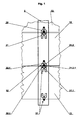
- FIG. 1 there are two connecting parts 31 and 32 at the gap between the two planks 11 and 12.
- the connecting parts lie largely under the planks and they rest entirely on the substructure 2 symbolized by a crossbar.
- the connecting part 31 is connected via a screw through its bore 31.1 with the screed 11. It protrudes with an extension 31.2 below the edge of the screed 11.
- At the extension 31.2 is a bore 31.2.1 through which the connecting part is connected via a further screw to the substructure 2.
- a connecting part 32 is attached via a screw through the bore 32.1.
- the connecting part 32 is not bolted to the substructure. It protrudes with extensions 32.2 under the screed 12 and below the adjacent screed 11 in the gap between this and the substructure into it.
- the screed 11 Since the screed 11 is connected to the substructure 2 in this area, thus the extensions 32.2 and with them the screed 12 are secured against lifting from the crossbar 2 away.
- the screed 12 is now equipped with a connecting part 31, which is connected to both the screed and with the substructure by a screw.
- the screed 13 is held at this gap by a connecting part 32 connected to it, which projects with projections under the screed 12.
- the part is screwed in any case at the edge of the underside of a screed. In one case, it protrudes with an extension (31.2), with which it is screwed to the substructure under this screed out; in the other case, it protrudes with extensions 32.3, which are not bolted to the substructure but extend below the adjacent screed.
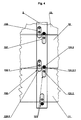
- FIG. 4 A particularly simple embodiment of the connecting parts 131, 132 which are also formed from the same part is shown in Fig. 4.
- the connecting parts are simply elongated plates with two consecutive holes. At the bore 131.1 or 132.1 approximately in the middle of the respective connecting part, each is Screwed connection part to a screed.
- the connecting parts 131 protrude with an extension 131.2, which is provided with a bore 131.2.1 under the screed and they are screwed through this hole also on the substructure 2.
- the connecting parts 132 protrude below the screed, namely into the gap between the underside of the adjacent screed and the substructure.
- the connecting part 132 is located close to the connecting part 131. If very wide slats for the substructure or even a flat adjacent substructure are present, however, the connecting parts 131 and 132 can also be arranged further apart from each other. It is also possible to use a smaller number of such connecting parts 132, which only make connections to the adjacent screed, than to connecting parts 131 which interact directly with the substructure.
- the connecting parts have a Y-shaped configuration, wherein the central web forms that extension 131.2 on which the connecting part is screwed to the crossbar.
- the two bifurcated webs form those extensions 32.3, which extend below the adjacent screed.
- the extension 31.2 of a connecting part 31 projects into the groove formed between the webs 32.2 of the second connecting part 32. So that the assembly does not need to be worked very accurately, the fit between the groove between the webs 32.2 and the extension 31.2 is designed as a very rough clearance fit.
- Fig. 4 is advantageous to the embodiment of FIGS.
- the connecting parts may be provided with notches 31.4, 32.4 or other markings characterizing those points at which the side edge of the lower surface of the board during assembly which is the connecting part attached, should run.
- the connecting parts are typically made of sheet steel. To save material - the connecting parts are mass-produced parts - should the connecting parts of a be made as thin sheet whose edges are bent for the sake of still good flexural rigidity (Fig. 3). It makes sense to mount the connecting parts thus formed with downwardly directed edge regions. In this way, forms under the surface of the connecting part a cavity in which the head of that screw which connects through the bore 31.1 or 32.1 the connecting part with a screed, place without a countersink of the screw through hole would be required.
- planks For the connection it does not matter which shape the longitudinal side surfaces of the planks have.
- the compound can also be applied to planks of a very hard or brittle material. If necessary, it is easy to pre-drill before screwing.
- the planks are not directly on the slats. There are no connecting parts at the top of the planks. The gap width between adjacent planks is freely selectable during assembly in a certain range. Last but not least, the parts required for the connection are inexpensive and easy to manufacture and assembly is easy. This fulfills the underlying task.
- connection is advantageously modified so that the two differently acting connecting parts are combined into a single part. That a single connecting part extends over the entire width of the underside of the screed and protrudes on both sides. On one side it is connected to the substructure, on the other side it reaches under the next adjacent screed.
Abstract
Description
Die Erfindung betrifft die Befestigung von Bohlen an einer Unterkonstruktion. Der wichtigste Anwendungsfall dafür ist die Bildung von bodenartigen Abdeckungen im Freien, beispielsweise Terassenabdeckungen.
Bohlen in diesem Sinne sind Stäbe, Profile oder langgestreckte Bretter, welche typischerweise aus Holz bestehen. Zur Bildung einer Abdeckung werden sie parallel zueinander, mit einem kleinen seitlichen Abstand zueinander, auf einer Unterkonstruktion, meist in Form einer Querlattung befestigt.
Die gängigste Methode die Bohlen an der Unterkonstruktion zu befestigen ist die, sie durch eine Schraube von der Oberseite der Bohlen her darauf anzuschrauben. Vorteilhaft an dieser Methode ist, daß sie einfach anzuwenden ist und daß außer Schrauben keine Befestigungsteile erforderlich sind. Nachteilig daran ist die gute Sichtbarkeit der Schraubenköpfe.
Entsprechend der DE 298 23 195 U1 und der EP 1 106 842 B1 werden Bohlen verwendet, welche an den Seitenflächen ihres Mantels mit einer Nut versehen sind. Die Bohlen durch Befestigungsteile gehalten, welche im Spalt zwischen zwei Bohlen durch Schrauben an der Unterkonstruktion befestigt sind und mit seitlichen Fortsätzen an den unteren Nutflanken der benachbarten Bohlen aufliegen. Nachteilig an dieser Befestigungsweise ist, daß sie nur bei Bohlen anwendbar ist, welche seitlich die entsprechende Profilform haben, daß die Spaltbreite zwischen benachbarten Bohlen nicht oder kaum varlierbar ist und daß die Bohlen direkt an der darunter liegenden Unterkonstruktion aufliegen, wodurch kriechende Feuchtigkeit mit all ihren negativen Folgewirkungen begünstigt wird.
Entsprechend der DE 102 30 797 A1 wird ein Befestigungsteil verwendet, welcher die Gestalt eines niedrigen, auf den Kopf gestellten T hat. Er erstreckt sich im Spalt zwischen zwei benachbarten Bohlen und unter diese. Mit der unteren Fläche ist der Befestigungsteil an der Lattung befestigt, vom Mittelsteg aus stecken Spitzen in den Seitenflächen der Bohlen und fixieren diese somit.
Nachteilig an dieser Befestigung ist, daß zu ihrer Herstellung ein Spezialwerkzeug erforderlich ist um die Spitzen in die Bohlen hineinzudrücken und daß sie bei solchen Bohlen die seitlich mit einer Nut versehen sind, nicht angewendet werden kann. Die Befestigung kann zudem nicht oder nur mit größten Schwierigkeiten angewendet werden, wenn die Bohlen aus sehr spröden Hölzern oder anderen Materialen mit ähnlichen Festigkeitseigenschaften bestehen, da dann die Spitzen des Befestigungsteiles nicht einfach in die Seitenflanken der Bohlen eingedrückt werden können.The invention relates to the attachment of planks to a substructure. The most important application for this is the formation of floor coverings outdoors, such as patio covers.
Planks in this sense are rods, profiles or elongated boards, which are typically made of wood. To form a cover they are mounted parallel to each other, with a small lateral distance from each other, on a substructure, usually in the form of a transverse battens.
The most common method of fixing the planks to the substructure is to screw them on top of the planks using a screw. An advantage of this method is that it is easy to use and that except screws no fasteners are required. The disadvantage of this is the good visibility of the screw heads.
According to DE 298 23 195 U1 and EP 1 106 842 B1 planks are used, which are provided on the side surfaces of their shell with a groove. The planks held by fasteners which are secured in the gap between two planks by screws to the substructure and rest with lateral projections on the lower groove flanks of the adjacent planks. A disadvantage of this attachment is that it is only applicable to planks, which laterally have the corresponding profile shape, that the gap width between adjacent planks is not or hardly varlesebar and that the planks rest directly on the underlying substructure, causing creeping moisture with all their negative consequences.
According to DE 102 30 797 A1 a fastening part is used, which has the shape of a low, upside down T. It extends in the gap between two adjacent planks and below them. With the lower surface of the fastening part is attached to the battens, from the central bridge tips stuck in the side surfaces of the boards and thus fix them.
A disadvantage of this attachment is that for their preparation, a special tool is required to push the tips into the planks and that they are provided in such planks laterally with a groove, can not be applied. The attachment can also not or only with great difficulty be applied if the planks of very brittle woods or other materials with similar strength properties, since then the tips of the fastening part can not be easily pressed into the side flanks of the planks.
Der Erfinder hat sich die Aufgabe gestellt eine Verbindung zwischen Bohlen und Lattung bereit zu stellen, welche möglichst universell, d.h. unabhängig von der Form der Seitenfläche der Bohlen und vom Material der Bohlen anwendbar ist. Randbedingungen dabei sind, daß keine Teile der Verbindung an der oberen Fläche der Bohlen sein dürfen, daß die Bohlen in einem kleinen definierten Abstand zur Lattung zu halten sind und daß die Spaltbreite zwischen benachbarten Bohlen zumindest in einem kleinen Bereich variierbar sein soll. Natürlich sollen die Teile für die Verbindung kostengünstig herzustellen und die Montage einfach sein.The inventor has set itself the task to provide a connection between planks and battens, which is as universal as possible, that is applicable regardless of the shape of the side surface of the planks and the material of the planks. Boundary conditions are that no parts of the compound must be on the upper surface of the planks, that the planks are to be kept at a small defined distance from the battens and that the gap width between adjacent planks should be variable at least in a small area. Of course, the parts for the connection to produce inexpensive and easy installation.
Zur Lösung der Aufgabe werden zwei unterschiedlich wirkende Verbindungsteile eingesetzt. Beide erstrecken sich an den Rändern der unteren Flächen der Bohlen zwischen diese und die Unterkonstruktion. Jeder der beiden Verbindungsteile ist mit der Unterseite einer Bohle verbunden. Der erste Verbindungsteil ragt an einer Seite der Bohle unter dieser hervor und ist dort mit der Unterkonstruktion verbunden. Der zweite Verbindungsteil ragt auf der anderen Seite der Bohle unter dieser hervor und erstreckt sich dort weiter bis unter die nächste Bohle und wird durch diese gegen Anheben von der Unterkonstruktion weg gehalten.To solve the problem, two differently acting connecting parts are used. Both extend at the edges of the lower surfaces of the planks between them and the substructure. Each of the two connecting parts is connected to the underside of a screed. The first connecting part protrudes on one side of the screed below this and is there connected to the substructure. The second connecting part protrudes on the other side of the screed below this and extends there to below the next plank and is held by this against lifting from the substructure.
Die Erfindung wird anhand der Zeichnungen, welche zwei vorteilhafte Ausführungsformen zeigen, anschaulicher;
- Fig. 1: -
- zeigt eine erfindungsgemaße Verbindung mit Blickrichtung von oben. Die Bohlen 11, 12, 13 sind dabei als durchsichtig angenommen und mit durchgehenden dünnen Linien symbolisiert dargestellt.
- Fig. 2: -
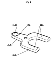
- zeigt einen Verbindungsteil von Fig. 1 im Schrägriß von oben.
- Fig. 3: -
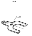
- zeigt einen Verbindungsteil von Fig. 1 im Schrägriß von unten.
- Fig. 4: -
- zeigt in gleicher Ansicht wie Fig. 1 eine weitere Ausführungsform der Verbindung.
- Fig. 1: -
- shows an inventive compound as viewed from above. The
planks - Fig. 2: -
- shows a connecting part of Fig. 1 in an oblique view from above.
- Fig. 3: -
- shows a connecting part of Fig. 1 in an oblique view from below.
- Fig. 4: -
- shows in the same view as Fig. 1, a further embodiment of the compound.
Wie in Fig. 1 gut erkennbar, befinden sich am Spalt zwischen den beiden Bohlen 11 und 12 zwei Verbindungsteile 31 und 32. Die Verbindungsteile liegen größtenteils unter den Bohlen und sie liegen zur Gänze auf der durch eine Latte symbolisierten Unterkonstruktion 2 auf.
Der Verbindungsteil 31 ist über eine Schraube durch seine Bohrung 31.1 mit der Bohle 11 verbunden. Er ragt mit einem Fortsatz 31.2 unter dem Rand der Bohle 11 hervor. Am Fortsatz 31.2 befindet sich eine Bohrung 31.2.1 durch welche der Verbindungsteil über eine weitere Schraube mit der Unterkonstruktion 2 verbunden ist.
An der Bohle 12 ist ein Verbindungsteil 32 über eine Schraube durch die Bohrung 32.1 angebracht. Der Verbindungsteil 32 ist nicht mit der Unterkonstruktion verschraubt. Er ragt mit Fortsätzen 32.2 unter der Bohle 12 hervor und unter die benachbarte Bohle 11 in den Spalt zwischen dieser und der Unterkonstruktion hinein. Da die Bohle 11 in diesem Bereich mit der Unterkonstruktion 2 verbunden ist, sind somit die Fortsätze 32.2 und mit ihnen die Bohle 12 gegen Anheben von der Latte 2 weg gesichert.
Am nächsten Spalt, jenem zwischen Bohle 12 und Bohle 13, ist nun die Bohle 12 mit einem Verbindungsteil 31 ausgestattet, welcher sowohl mit der Bohle als auch mit der Unterkonstruktion durch jeweils eine Schraube verbunden ist. Die Bohle 13 wird an diesem Spalt durch einen mit ihr verbundenen Verbindungsteil 32 gehalten, welcher mit Fortsätzen unter die Bohle 12 ragt.As can be clearly seen in FIG. 1, there are two connecting
The connecting
On the
At the next gap, that between screed 12 and Bohle 13, the screed 12 is now equipped with a connecting
Dieses System wird bis zur letzten Bohle beibehalten.This system is maintained until the last screed.
An jener Längsseite der ersten Bohle 11, an welcher sich keine benachbarte Bohle befindet, ist diese ebenfalls mit einem Verbindungsteil 31 ausgestattet der sowohl mit ihr als auch mit der Unterkonstruktion durch eine Schraube verbunden ist.On that longitudinal side of the first screed 11, on which there is no adjacent screed, this is also equipped with a connecting
Die Arbeit zur Montage der Bohlen kann in folgenden Schritten erfolgen:
- 1. Erste Bohle (11) mit der oberen Seite nach unten aber mit passender Längsausrichtung auf die Unterkonstruktion auflegen.
- 2. Über jeder Latte der Unterkonstruktion an beiden Rändern der Unterseite der Bohle einen
Verbindungsteil 31 über die Bohrung 31.1 an der Bohle so festschrauben, daß ein Fortsatz 31.2 des Verbindungsteils über den Rand der Unterseite der Bohle hinausragt. - 3. Die Bohle um ihre Längsachse drehen, sodaß sie über die
Verbindungsteile 31 auf der Unterkonstruktion aufliegt und über die Bohrungen 31.2.1 an derUnterkonstruktion 2 festschrauben. - 4. Die zweite (nächste) Bohle (12) auf die schon montierte Bohle längenrichtig aber mit der Oberseite nach unten auflegen.
- 5. Über jeder Latte der Unterkonstruktion auf der den weiteren Bohlen zugekehrten Seite der nun oben liegenden Unterseite einen
Verbindungsteil 32 durch die Bohrung 32.1 mit einer Schraube befestigen, an der anderen Seite der Unterseite einenVerbindungsteil 31 befestigen. - 6. Bohle um 180° um ihre Längsachse drehen, neben der vorherigen Bohle längenrichtig auf die Unterkonstruktion legen und an die vorherige Bohle schieben, sodaß die Fortsätze 32.3 unter die vorher montierte Bohle gleiten. Die richtige Spaltbreite zwischen den Bohlen durch einen Anschlagteil, welcher während des Zusammenschiebens zwischen die Bohlen gehalten wird, einstellen.
- 7. Die noch freien Fortsätze 31.2
der Verbindungsteile 32 an der soeben hingelegten Bohle durch die Bohrungen 31.2.1 an der Unterkonstruktion festschrauben.- Wiederholung der Schritte 4 bis 7 bis auch die letzten Bohle so befestigt ist. Fertig.
- 1. Place the first screed (11) with the upper side downwards but with the appropriate longitudinal alignment on the substructure.
- 2. Screw a connecting
part 31 over each lath of the substructure at both edges of the underside of the screed over the hole 31.1 on the screed so that an extension 31.2 of the connecting part projects beyond the edge of the underside of the screed. - 3. Rotate the screed about its longitudinal axis, so that it rests on the connecting
parts 31 on the substructure and screw on the bores 31.2.1 to thesubstructure 2. - 4. Place the second (next) screed (12) on the already installed screed lengthwise but upside down.
- 5. Fasten a connecting
part 32 through the hole 32.1 with a screw over each lath of the substructure on the side facing the other planks facing the underside of the underside, fasten a connectingpart 31 on the other side of the underside. - 6. Turn the screed 180 ° around its longitudinal axis, place it next to the previous screed lengthwise on the substructure and push it to the previous screed so that the protrusions 32.3 slide under the previously installed screed. Adjust the correct gap width between the planks by means of an abutment which is held between the planks during assembly.
- 7. Tighten the still free extensions 31.2 of the connecting
parts 32 to the just laid screed through the holes 31.2.1 on the substructure.- Repeat steps 4 to 7 until the last screed is attached. Finished.
Wie schon aus Fig. 1 ersichtlich, kann für die unterschiedlich eingesetzten Verbindungsteile 31 und 32 genau der gleiche Teil verwendet werden. Der Teil wird in jedem Fall am Rand der Unterseite einer Bohle festgeschraubt. Im einen Fall ragt er mit einem Fortsatz (31.2), mit dem er mit der Unterkonstruktion verschraubt wird unter dieser Bohle hervor; im anderen Fall ragt er mit Fortsätzen 32.3 hervor, welche nicht mit der Unterkonstruktion verschraubt werden aber unter die benachbarte Bohle reichen.As can already be seen from FIG. 1, exactly the same part can be used for the connecting
Eine besonders einfache Ausführungsform der Verbindungsteile 131, 132 die ebenfalls aus dem gleichen Teil gebildet werden ist in Fig. 4 dargestellt. Die Verbindungsteile sind einfach längliche Plättchen mit zwei hintereinanderliegenden Bohrungen. An der Bohrung 131.1 bzw. 132.1 etwa in der Mitte des jeweiligen Verbindungsteiles, ist jeder Verbindungsteil an einer Bohle festgeschraubt. Die Verbindungsteile 131 ragen mit einem Fortsatz 131.2, welcher mit einer Bohrung 131.2.1 versehen ist unter der Bohle hervor und sie sind durch diese Bohrung auch an der Unterkonstruktion 2 festgeschraubt. Mit einem Fortsatz 132.3 ragen die Verbindungsteile 132 unter der Bohle hervor und zwar bis in den Spalt zwischen der Unterseite der benachbarte Bohle und der Unterkonstruktion hinein.A particularly simple embodiment of the connecting
Aus Gründen der Steifigkeit ist es vorteilhaft, wenn sich der Verbindungsteil 132 nahe am Verbindungsteil 131 befindet. Wenn sehr breite Latten für die Unterkonstruktion oder überhaupt eine flächige angrenzende Unterkonstruktion vorliegen, können die Verbindungsteile 131 und 132 aber auch weiter voneinander entfernt angeordnet sein. Es kann auch eine kleinere Anzahl von solchen Verbindungsteilen 132 verwendet werden, welche nur Verbindungen zur benachbarten Bohle herstellen, als von Verbindungsteilen 131 welche direkt mit der Unterkonstruktion zusammenwirken.For reasons of rigidity, it is advantageous if the connecting
Bei der Ausführung gemäß Fig. 1 bis Fig. 3 haben die Verbindungsteile Y-förmige Gestalt, wobei der Mittelsteg jenen Fortsatz 131.2 bildet an welchem der Verbindungsteil an der Latte festgeschraubt wird. Die beiden gegabelten Stege bilden jene Fortsätze 32.3, welche unter die benachbarte Bohle reichen. In montiertem Zustand liegen an jedem Spalt zwischen zwei Bohlen an jeder Latte der Unterkonstruktion zwei gleich ausgerichtete Verbindungsteile so hintereinander, daß der Fortsatz 31.2 des einen Verbindungsteils 31 in die zwischen den Stegen 32.2 des zweiten Verbindungsteiles 32 gebildete Nut ragt. Damit bei der Montage nicht sehr genau gearbeitet zu werden braucht ist die Passung zwischen der Nut zwischen den Stegen 32.2 und dem Fortsatz 31.2 als sehr grobe Spielpassung ausgeführt.
Gegenüber der Ausführungsform von Fig. 4 ist an der Ausführungsform gemäß Fig. 1 bis 3 vorteilhaft, daß der Verbindungsteil 32, welcher nicht mit der Latte verschraubt ist, die Bohle an welcher er befestigt ist, steifer hält als der vergleichbare Teil 132.. Weiters ist diese Ausführungsform durch die Symmetrie und durch das Ineinandergreifen der Befestigungsteile 31 und 32 sehr einleuchtend, sodaß sie auch von Laien extrem schnell verstanden und fehlerfrei angewendet werden kann.In the embodiment according to FIGS. 1 to 3, the connecting parts have a Y-shaped configuration, wherein the central web forms that extension 131.2 on which the connecting part is screwed to the crossbar. The two bifurcated webs form those extensions 32.3, which extend below the adjacent screed. In the assembled state are at each gap between two planks on each bar of the substructure two identically aligned connecting parts in a row, that the extension 31.2 of a connecting
Compared to the embodiment of Fig. 4 is advantageous to the embodiment of FIGS. 1 to 3, that the connecting
Um die Montage zu erleichtern können - wie in Fig. 2 und Fig. 3 gut erkennbar - die Verbindungsteile mit Einkerbungen 31.4, 32.4 oder anderen Markierungen versehen sein, welche jene Stellen kennzeichnen, an denen bei der Montage die Seitenkante der unteren Fläche der Bohle an welcher der Verbindungsteil befestigt wird, verlaufen soll.In order to facilitate assembly - as clearly visible in Fig. 2 and Fig. 3 - the connecting parts may be provided with notches 31.4, 32.4 or other markings characterizing those points at which the side edge of the lower surface of the board during assembly which is the connecting part attached, should run.
Es ist vortelhaft die Bohrungen 31.2.1, 131.2.1 angesenkt auszuführen (Fig. 2, Fig. 3). Am Rand der aus Bohlen gebildeten Abdeckung sind die Köpfe der durch diese Bohrungen ansetzenden Schrauben sichtbar und sollten daher versenkbar sein.It is vortelhaft the holes 31.2.1, 131.2.1 carried out lowered (Fig. 2, Fig. 3). At the edge of the cover formed from planks, the heads of attaching through these holes screws are visible and should therefore be retractable.
Die Verbindungsteile bestehen typischerweise aus Stahlblech. Um Material zu sparen - die Verbindungsteile sind Großserienteile - sollten die Verbindungsteile aus einem möglichst dünnen Blech hergestellt werden dessen Ränder zwecks dennoch guter Biegesteifigkeit aufgebogenen werden (Fig. 3). Es ist sinnvoll die so gebildeten Verbindungsteile mit nach unten gerichteten Randbereichen zu montieren. Auf diese Weise bildet sich unter der Fläche des Verbindungsteiles ein Hohlraum in welchem der Kopf jener Schraube die durch die Bohrung 31.1 bzw. 32.1 den Verbindungsteil mit einer Bohle verbindet, Platz findet ohne daß eine Ansenkung der Schraubendurchgangsbohrung erforderlich wäre.The connecting parts are typically made of sheet steel. To save material - the connecting parts are mass-produced parts - should the connecting parts of a be made as thin sheet whose edges are bent for the sake of still good flexural rigidity (Fig. 3). It makes sense to mount the connecting parts thus formed with downwardly directed edge regions. In this way, forms under the surface of the connecting part a cavity in which the head of that screw which connects through the bore 31.1 or 32.1 the connecting part with a screed, place without a countersink of the screw through hole would be required.
Für die Verbindung ist es egal welche Form die Längsseitenflächen der Bohlen haben. Die Verbindung kann auch bei Bohlen aus einem sehr harten oder spröden Material angewendet werden. Erforderlichenfalls kann vor dem Schrauben einfach vorgebohrt werden. Die Bohlen liegen nicht direkt auf den Latten auf. Es befinden sich keine Verbindungsteile an der Oberseite der Bohlen. Der Spaltbreite zwischen benachbarten Bohlen ist bei der Montage in einem gewissen Bereich frei wählbar. Nicht zuletzt sind die für die Verbindung erforderlichen Teile kostengünstig und einfach herzustellen und die Montage ist einfach. Damit ist die zugrunde liegende Aufgabe erfüllt.For the connection it does not matter which shape the longitudinal side surfaces of the planks have. The compound can also be applied to planks of a very hard or brittle material. If necessary, it is easy to pre-drill before screwing. The planks are not directly on the slats. There are no connecting parts at the top of the planks. The gap width between adjacent planks is freely selectable during assembly in a certain range. Last but not least, the parts required for the connection are inexpensive and easy to manufacture and assembly is easy. This fulfills the underlying task.
Folgende Abwandlungen der beschriebenen Verbindung sind dann möglich und evtl. sinnvoll, wenn keine sehr harten oder spröden Materialien für Bohlen oder Unterkonstruktion verwendet werden:
- An Stelle der Bohrungen 31.1, 131.1, 32.1, 132.1 und den Schrauben bzw. Nägeln mit denen die Verbindung zur Bohle hergestellt wird, kann auch ein Spieß direkt am Verbindungsteil engeformt sein. Zur Verbindung des Teils mit der Bohle wird der Teil dann passend auf die Bohle aufgelegt und dann mit einem Hammer angeschlagen, sodaß der Spieß in das Material der Bohle eindringt.
- An Stelle von Schrauben können auch Nägel verwendet werden.
- An Stelle einer Bohrung 31.2.1, 131.2.1 im Fortsatz 31.2, 131.2 und einer Schraube durch diese Bohrung kann beispielsweise auch eine U-förmige Klammer verwendet werden, welche quer über den Fortsatz und in die darunter liegende Unterkonstruktion hinein verläuft.
- Instead of the holes 31.1, 131.1, 32.1, 132.1 and the screws or nails with which the connection is made to the screed, a skewer can be close-formed directly on the connecting part. To connect the part with the screed, the part is then placed suitably on the screed and then struck with a hammer, so that the spit penetrates into the material of the screed.
- Nails can be used instead of screws.
- Instead of a bore 31.2.1, 131.2.1 in the extension 31.2, 131.2 and a screw through this hole, for example, a U-shaped bracket can be used, which extends transversely across the extension and into the underlying substructure inside.
Für sehr schlanke Bohlen ist die Verbindung vorteilhaft so abgewandelt, daß die beiden unterschiedlich wirkenden Verbindungsteile zu einem einzigen Teil zusammengefaß sind. D.h. ein einziger Verbindungsteil erstreckt sich über die ganze Breite der Unterseite der Bohle und steht an beiden Seiten vor. An der einen Seite wird er mit der Unterkonstruktion verbunden, an der anderen Seite reicht er unter die nächste benachbarte Bohle.For very slender planks, the connection is advantageously modified so that the two differently acting connecting parts are combined into a single part. That a single connecting part extends over the entire width of the underside of the screed and protrudes on both sides. On one side it is connected to the substructure, on the other side it reaches under the next adjacent screed.
Claims (9)
Applications Claiming Priority (1)
| Application Number | Priority Date | Filing Date | Title |
|---|---|---|---|
| AT0133404A AT414029B (en) | 2004-08-04 | 2004-08-04 | ATTACHING BOILES TO A SUB-CONSTRUCTION |
Publications (2)
| Publication Number | Publication Date |
|---|---|
| EP1635008A2 true EP1635008A2 (en) | 2006-03-15 |
| EP1635008A3 EP1635008A3 (en) | 2008-01-23 |
Family
ID=35116105
Family Applications (1)
| Application Number | Title | Priority Date | Filing Date |
|---|---|---|---|
| EP05016843A Withdrawn EP1635008A3 (en) | 2004-08-04 | 2005-08-02 | Fastening of planks to a sub-construction |
Country Status (2)
| Country | Link |
|---|---|
| EP (1) | EP1635008A3 (en) |
| AT (1) | AT414029B (en) |
Cited By (11)
| Publication number | Priority date | Publication date | Assignee | Title |
|---|---|---|---|---|
| GB2434829A (en) * | 2005-08-19 | 2007-08-08 | Handy & Harman | Hidden deck fastener system |
| DE102006035805B3 (en) * | 2006-08-01 | 2007-11-08 | Markus Rensburg | Board-linking element for fitting on two boards so as to stop a dishing effect consists of a single-piece flat element in the shape of a cube with three areas |
| DE102006036642A1 (en) * | 2006-08-03 | 2008-02-14 | Göttlicher GmbH & Co. KG | Installation jig for wooden decking has tongue that co-locates adjacent planks with intermediate gap |
| DE202008010795U1 (en) | 2008-08-05 | 2009-01-02 | Bierbach Gmbh & Co. Kg, Befestigungstechnik | Fastening element for concealed attachment of wooden floorboards to a substructure |
| DE102008048559A1 (en) * | 2008-09-23 | 2010-05-20 | Knapp, Friedrich | Fixing structure for terrace floors, has plastic plates with thickened section fixed to lower side of bearing beams so that gaps are formed between upper side of support beams and lower side of plastic plate-sections |
| DE102009008454A1 (en) * | 2009-02-11 | 2010-08-19 | Ulrich Reif | Leveling aid for wooden / beam substructures, especially for balcony and terrace coverings |
| EP2184421A3 (en) * | 2008-11-07 | 2011-03-23 | Günter Rubner | Fastening element for a positioning system for creating a wall, floor or ceiling screed and such a positioning system |
| WO2011021950A3 (en) * | 2009-08-17 | 2011-07-07 | Grzegorz Baranowski | Deck and its method of assembling |
| AT514463A1 (en) * | 2013-06-20 | 2015-01-15 | Procon Gmbh Maschinen & Industrieanlagen | Spacer element for hanging wall and sight elements |
| EP2995742A3 (en) * | 2014-08-14 | 2016-04-06 | Stefan Ehrenreich | End floorboard retention device for a floorboard assembly |
| EP2527550A3 (en) * | 2011-05-10 | 2017-06-14 | SIHGA GmbH | Fitting for connecting the planks of a terrace covering with a substructure beneath it |
Families Citing this family (1)
| Publication number | Priority date | Publication date | Assignee | Title |
|---|---|---|---|---|
| DE202008016278U1 (en) * | 2008-12-09 | 2009-02-26 | Bahr, Jens-Oliver, Dipl.-Designer | Invisible fitting for the production of a wooden floor in the lath composite for the outside area (for example terrace) |
Citations (3)
| Publication number | Priority date | Publication date | Assignee | Title |
|---|---|---|---|---|
| DE29823195U1 (en) | 1998-12-29 | 1999-02-18 | Ostermann & Scheiwe Gmbh & Co | Composite of boards |
| DE10230797A1 (en) | 2001-07-16 | 2003-02-27 | Reif Dieter | Fixing clip for connecting wooden components together and on a subconstruction comprises a double angle plate consisting of two L-shaped profiles |
| EP1106842B1 (en) | 1999-12-03 | 2004-01-28 | Compagnie des Bois - Architecture et Ingenierie, Sarl | Connecting device for wooden strips without visible screw |
Family Cites Families (5)
| Publication number | Priority date | Publication date | Assignee | Title |
|---|---|---|---|---|
| US3047985A (en) * | 1957-05-06 | 1962-08-07 | Jean C Chognard | Panel tie |
| US4221095A (en) * | 1978-09-29 | 1980-09-09 | Weinar Roger N | Wall constructed from wallboard held together with concealed fasteners |
| AU4492285A (en) * | 1984-06-22 | 1986-01-24 | O. Hovde | Panelling system and panelling clips for the same |
| DE3619287A1 (en) * | 1986-06-07 | 1987-12-10 | Dieter Dipl Ing Wolff | HOLDING ELEMENT FOR WALL AND FLOOR PANELS |
| US4844651A (en) * | 1987-07-30 | 1989-07-04 | Partridge Juergen W | Fastening clip |
-
2004
- 2004-08-04 AT AT0133404A patent/AT414029B/en active
-
2005
- 2005-08-02 EP EP05016843A patent/EP1635008A3/en not_active Withdrawn
Patent Citations (3)
| Publication number | Priority date | Publication date | Assignee | Title |
|---|---|---|---|---|
| DE29823195U1 (en) | 1998-12-29 | 1999-02-18 | Ostermann & Scheiwe Gmbh & Co | Composite of boards |
| EP1106842B1 (en) | 1999-12-03 | 2004-01-28 | Compagnie des Bois - Architecture et Ingenierie, Sarl | Connecting device for wooden strips without visible screw |
| DE10230797A1 (en) | 2001-07-16 | 2003-02-27 | Reif Dieter | Fixing clip for connecting wooden components together and on a subconstruction comprises a double angle plate consisting of two L-shaped profiles |
Cited By (17)
| Publication number | Priority date | Publication date | Assignee | Title |
|---|---|---|---|---|
| GB2434829A (en) * | 2005-08-19 | 2007-08-08 | Handy & Harman | Hidden deck fastener system |
| GB2434829B (en) * | 2005-08-19 | 2008-03-19 | Handy & Harman | Hidden deck fastener system |
| US7516586B2 (en) | 2005-08-19 | 2009-04-14 | Handy & Harman | Hidden deck fastener system |
| DE102006035805B3 (en) * | 2006-08-01 | 2007-11-08 | Markus Rensburg | Board-linking element for fitting on two boards so as to stop a dishing effect consists of a single-piece flat element in the shape of a cube with three areas |
| DE202007018793U1 (en) | 2006-08-01 | 2009-04-30 | Rensburg, Markus | Bar link |
| DE202007018836U1 (en) | 2006-08-01 | 2009-07-02 | Rensburg, Markus | Bar link |
| DE102006036642A1 (en) * | 2006-08-03 | 2008-02-14 | Göttlicher GmbH & Co. KG | Installation jig for wooden decking has tongue that co-locates adjacent planks with intermediate gap |
| DE202008010795U1 (en) | 2008-08-05 | 2009-01-02 | Bierbach Gmbh & Co. Kg, Befestigungstechnik | Fastening element for concealed attachment of wooden floorboards to a substructure |
| DE102008048559A1 (en) * | 2008-09-23 | 2010-05-20 | Knapp, Friedrich | Fixing structure for terrace floors, has plastic plates with thickened section fixed to lower side of bearing beams so that gaps are formed between upper side of support beams and lower side of plastic plate-sections |
| DE102008048559B4 (en) * | 2008-09-23 | 2013-03-21 | Friedrich Knapp | Fixing construction for terrace floors |
| EP2184421A3 (en) * | 2008-11-07 | 2011-03-23 | Günter Rubner | Fastening element for a positioning system for creating a wall, floor or ceiling screed and such a positioning system |
| DE102009008454A1 (en) * | 2009-02-11 | 2010-08-19 | Ulrich Reif | Leveling aid for wooden / beam substructures, especially for balcony and terrace coverings |
| WO2011021950A3 (en) * | 2009-08-17 | 2011-07-07 | Grzegorz Baranowski | Deck and its method of assembling |
| EP2527550A3 (en) * | 2011-05-10 | 2017-06-14 | SIHGA GmbH | Fitting for connecting the planks of a terrace covering with a substructure beneath it |
| AT514463A1 (en) * | 2013-06-20 | 2015-01-15 | Procon Gmbh Maschinen & Industrieanlagen | Spacer element for hanging wall and sight elements |
| AT514463B1 (en) * | 2013-06-20 | 2015-03-15 | Procon Gmbh Maschinen & Industrieanlagen | Spacer element for hanging wall and sight elements |
| EP2995742A3 (en) * | 2014-08-14 | 2016-04-06 | Stefan Ehrenreich | End floorboard retention device for a floorboard assembly |
Also Published As
| Publication number | Publication date |
|---|---|
| EP1635008A3 (en) | 2008-01-23 |
| ATA13342004A (en) | 2005-11-15 |
| AT414029B (en) | 2006-08-15 |
Similar Documents
| Publication | Publication Date | Title |
|---|---|---|
| EP1635008A2 (en) | Fastening of planks to a sub-construction | |
| DE2525791C3 (en) | Arrangement for connecting two abutting plate or rod-shaped elements | |
| AT515684B1 (en) | Facade system and a holding part for fixing two visible profiles | |
| AT13587U2 (en) | connecting device | |
| DE102009043993A1 (en) | Distance element to the floorboards of a floor bearing attachment to a support beam | |
| AT8351U1 (en) | DEVICE FOR FIXING BRETTES | |
| DE202008010795U1 (en) | Fastening element for concealed attachment of wooden floorboards to a substructure | |
| DE202012104033U1 (en) | Holding device for a balustrade or railing plate and railing or parapet with disc | |
| AT15732U1 (en) | Fastening element for fastening a facade cladding element to a substructure, and a facade cladding system | |
| DE60312728T2 (en) | Kit with a parquet rod and a mounting bracket for this | |
| EP2584114A2 (en) | Facade structure and holder thereof | |
| EP0716198B1 (en) | Device for fastening façade slabs | |
| EP2845965B1 (en) | Mounting of planks to a substructure | |
| EP1245754A1 (en) | Locking system for sports floors | |
| DE4026688A1 (en) | Radar-absorbent wall panelling - has horizontal rails which hold both lower edges of one row and tops of underlying row of ceramic elements | |
| EP3296486B1 (en) | Building cladding with a fitting set for the joining of elongated cover elements | |
| AT401788B (en) | FACADE | |
| CH717142B1 (en) | Connecting device for connecting floorboards or panels to beams. | |
| DE202019100539U1 (en) | Substructure arrangement for a substructure of a terrace or other floor | |
| DE3636565A1 (en) | Ceramic facade panels, and facades produced from panels of this type | |
| DE3641747C2 (en) | Facade panels for attachment to a slatted frame and retaining clip for fixing such facade panels to the slatted frame | |
| EP2944740B1 (en) | Assembly and compound body | |
| DE102010048218B4 (en) | suspension fitting | |
| EP0670398B1 (en) | Angle-bar | |
| EP1424456A1 (en) | Device for anchoring facade panels to a wall surface |
Legal Events
| Date | Code | Title | Description |
|---|---|---|---|
| PUAI | Public reference made under article 153(3) epc to a published international application that has entered the european phase |
Free format text: ORIGINAL CODE: 0009012 |
|
| AK | Designated contracting states |
Kind code of ref document: A2 Designated state(s): AT BE BG CH CY CZ DE DK EE ES FI FR GB GR HU IE IS IT LI LT LU LV MC NL PL PT RO SE SI SK TR |
|
| AX | Request for extension of the european patent |
Extension state: AL BA HR MK YU |
|
| RIN1 | Information on inventor provided before grant (corrected) |
Inventor name: KIESLINGER, KLAUS |
|
| PUAL | Search report despatched |
Free format text: ORIGINAL CODE: 0009013 |
|
| RIC1 | Information provided on ipc code assigned before grant |
Ipc: E04B 5/12 20060101ALI20071213BHEP Ipc: E04F 15/04 20060101AFI20051027BHEP |
|
| AK | Designated contracting states |
Kind code of ref document: A3 Designated state(s): AT BE BG CH CY CZ DE DK EE ES FI FR GB GR HU IE IS IT LI LT LU LV MC NL PL PT RO SE SI SK TR |
|
| AX | Request for extension of the european patent |
Extension state: AL BA HR MK YU |
|
| AKX | Designation fees paid | ||
| REG | Reference to a national code |
Ref country code: DE Ref legal event code: 8566 |
|
| STAA | Information on the status of an ep patent application or granted ep patent |
Free format text: STATUS: THE APPLICATION IS DEEMED TO BE WITHDRAWN |
|
| 18D | Application deemed to be withdrawn |
Effective date: 20080724 |