EP1634842A2 - Wedge clamp for belt driven elevator - Google Patents
Wedge clamp for belt driven elevator Download PDFInfo
- Publication number
- EP1634842A2 EP1634842A2 EP05108148A EP05108148A EP1634842A2 EP 1634842 A2 EP1634842 A2 EP 1634842A2 EP 05108148 A EP05108148 A EP 05108148A EP 05108148 A EP05108148 A EP 05108148A EP 1634842 A2 EP1634842 A2 EP 1634842A2
- Authority
- EP
- European Patent Office
- Prior art keywords
- belt
- wedge
- riemenendverbindung
- support belt
- rotation
- Prior art date
- Legal status (The legal status is an assumption and is not a legal conclusion. Google has not performed a legal analysis and makes no representation as to the accuracy of the status listed.)
- Pending
Links
Images


Classifications
-
- B—PERFORMING OPERATIONS; TRANSPORTING
- B66—HOISTING; LIFTING; HAULING
- B66B—ELEVATORS; ESCALATORS OR MOVING WALKWAYS
- B66B7/00—Other common features of elevators
- B66B7/06—Arrangements of ropes or cables
- B66B7/08—Arrangements of ropes or cables for connection to the cars or cages, e.g. couplings
- B66B7/085—Belt termination devices
-
- Y—GENERAL TAGGING OF NEW TECHNOLOGICAL DEVELOPMENTS; GENERAL TAGGING OF CROSS-SECTIONAL TECHNOLOGIES SPANNING OVER SEVERAL SECTIONS OF THE IPC; TECHNICAL SUBJECTS COVERED BY FORMER USPC CROSS-REFERENCE ART COLLECTIONS [XRACs] AND DIGESTS
- Y10—TECHNICAL SUBJECTS COVERED BY FORMER USPC
- Y10T—TECHNICAL SUBJECTS COVERED BY FORMER US CLASSIFICATION
- Y10T24/00—Buckles, buttons, clasps, etc.
- Y10T24/39—Cord and rope holders
- Y10T24/3909—Plural-strand cord or rope
-
- Y—GENERAL TAGGING OF NEW TECHNOLOGICAL DEVELOPMENTS; GENERAL TAGGING OF CROSS-SECTIONAL TECHNOLOGIES SPANNING OVER SEVERAL SECTIONS OF THE IPC; TECHNICAL SUBJECTS COVERED BY FORMER USPC CROSS-REFERENCE ART COLLECTIONS [XRACs] AND DIGESTS
- Y10—TECHNICAL SUBJECTS COVERED BY FORMER USPC
- Y10T—TECHNICAL SUBJECTS COVERED BY FORMER US CLASSIFICATION
- Y10T24/00—Buckles, buttons, clasps, etc.
- Y10T24/39—Cord and rope holders
- Y10T24/3969—Sliding part or wedge
- Y10T24/3971—Rope looped about movable member
-
- Y—GENERAL TAGGING OF NEW TECHNOLOGICAL DEVELOPMENTS; GENERAL TAGGING OF CROSS-SECTIONAL TECHNOLOGIES SPANNING OVER SEVERAL SECTIONS OF THE IPC; TECHNICAL SUBJECTS COVERED BY FORMER USPC CROSS-REFERENCE ART COLLECTIONS [XRACs] AND DIGESTS
- Y10—TECHNICAL SUBJECTS COVERED BY FORMER USPC
- Y10T—TECHNICAL SUBJECTS COVERED BY FORMER US CLASSIFICATION
- Y10T24/00—Buckles, buttons, clasps, etc.
- Y10T24/39—Cord and rope holders
- Y10T24/3996—Sliding wedge
Definitions
- the present invention relates to a belt end connection for fastening a belt end in an elevator installation and method for the protection and testing of a belt end connection in an elevator installation.
- An elevator system usually consists of a car and a counterweight, which are moved in opposite directions in an elevator shaft.
- the cab and the counterweight are connected and supported by carrying straps.
- One end of the support belt is fastened with a belt end connection to the car, or to the counterweight or in the elevator shaft.
- the location of attachment depends on the embodiment of the elevator system. Accordingly, the belt end connection must transmit the force acting in the support belt to the car or counterweight or to the elevator shaft. It must therefore be designed so that it can safely transmit the allowable load capacity of the belt.
- the mounting direction of the Riemenenditati depends on the location of the attachment. When the belt end connection is attached to the car or to the counterweight, a pulling direction of the carrying belt is usually directed upwards; when the belt end connection is mounted in the elevator shaft, the pulling direction of the carrying belt is usually directed downwards.
- the strap is held by a wedge in a wedge pocket.
- a first Keiltaschen preparation here is designed according to the pulling direction of the support belt.
- This first key pocket surface is arranged in the withdrawal direction of the support belt.
- a second key pocket surface is designed to be displaced according to a wedge angle of the wedge relative to the first key pocket surface.
- the strap is now between Keiltaschen vom and Wedge arranged and he pulls the wedge due to the friction conditions in the wedge pocket, whereby the strap is clamped.
- a twisting of the belt end connection can occur when the support belt experiences a torque, for example, as a result of manufacturing tolerances of the support belt itself or as a result of arrangements of fastening and deflection points.
- This torque causes rotation about a longitudinal axis of the belt end connection.
- the longitudinal axis corresponds to a direction of action of the load-bearing force acting in the carrying belt.
- the Riemenendharm should be inexpensive, their handling during assembly and maintenance should be easy and they should promote high availability of the elevator system.
- the invention relates to a belt end connection for fastening a belt end in an elevator installation and method for the protection and testing of a belt end connection in an elevator installation according to the definition of the patent claims.
- the elevator system consists of a car and a counterweight, which are moved in opposite directions in an elevator shaft.
- the cab and the counterweight are connected and supported by carrying straps.
- One end of the support belt is attached to the car, counterweight or hoistway with a belt end connection. The location of attachment depends on the embodiment of the elevator system.
- the carrying strap is held in the belt end connection by means of a wedge which fixes the carrying means in a wedge pocket.
- a rotation protection which prevents rotation of the Riemenenditati about its longitudinal axis.
- the longitudinal axis corresponds to the defined by the effective direction of the carrying capacity in the strap direction.
- the advantage of this invention is that the susceptibility of the RiemenendENS is reduced because the strap does not twist even with loose strap.
- the anti-rotation can be provided inexpensively and it is easy to install. This solution provides an effective method of protecting the belt end fastener and associated strap from damage.
- the anti-rotation protection allows efficient testing of correct installation of the belt end attachment and thus simplifies control of the belt end attachment within the framework of the upkeep of the elevator installation.
- the wedge which fixes the carrying strap in the wedge pocket of the belt end connection, is secured against slipping out of the wedge bag by means of a loss guard.
- the advantage of this invention is that the susceptibility to damage of the belt end connection is reduced because the wedge can not slip out of the wedge pocket and thereby does not result in injury to the support belt due to a loose wedge.
- the solution is cost effective and can be assembled quickly without the need for special tools. This solution is an effective way to protect the belt end fitting and its strap from damage.
- the anti-loss device allows efficient testing and control of proper installation of the belt end attachment.
- the elevator installation 1 consists, as shown in FIGS. 1 and 2, of a cabin 3 and a counterweight 4, which are moved in opposite directions in an elevator shaft 2.
- Cabin 3 and counterweight 4 are connected to each other by means of strap 6 and carried.
- One end of the support belt 6 is fastened with a belt end connection 9 to the car 3, or counterweight 4, according to FIG. 2, or in the elevator shaft 2, according to FIG. 1.
- the location of attachment depends on the embodiment of the elevator system. 1 3 and 4 it can be seen how the carrying strap 6 is held in the belt end connection 9 by means of a wedge 12 which fixes the carrying strap in a wedge pocket 11.
- the Riemenendbefest Trent is connected to the car 3, or the counterweight 4 or to the elevator shaft 2.
- a twist 21 is used.
- the anti-rotation 21 prevents rotation of the Riemenendtell and the support belt 6 about the longitudinal axis zz 'effectively.
- the longitudinal axis zz ' corresponds to the effective direction of the carrying capacity in the carrying strap 6.
- the anti-rotation 21 twisting the belt connection 9 and the associated support belt 6 is effectively prevented. An uneven loading of the support belt 6 or damage to the support belt 6, is effectively prevented.
- the anti-rotation 21 is inexpensive and it is easy to install. It allows efficient control of the condition of the belt end connection 9, thereby improving its availability.
- the anti-rotation 21 is a flat profile 22, as shown in FIGS. 5, 7 and 8 by way of example.
- the flat profile is for example a sheet steel strip.
- the flat profile 22 is arranged in the illustrated example, in the vicinity of the Riemenendthetic 9, in surface contact with the strap 6.
- the anti-rotation 21 between a supporting Trumm 8 of the support belt 6 and loose Trumm 7 of the support belt 6 is attached.
- This embodiment is advantageous because with only a simple twist protection 21 a protection against rotation is achieved. This is inexpensive.
- the anti-rotation 21 may be disposed outside of the supporting and / or loose Trumms 7.8 of the support belt 6. With this embodiment, for example, retrofitting a Vermostikes in an existing elevator system 1 is easily possible.
- a specially shaped anti-rotation 21 may also include the strap 6. This allows special adjustments to the local mounting options.
- the anti-rotation 21 can connect two strap 6 together and / or he can connect one or more strap 6 with a portion of the elevator system.
- the belt end connection 9 is thus connected, directly or indirectly, to at least one further belt end connection and / or to a part of the elevator installation.
- a direct connection can be made by the anti-rotation 21 is arranged for example on a wedge housing 11 comprehensive wedge housing 10.
- An indirect connection can be made by the anti-rotation 21 is arranged for example on the strap 6.
- connection arrangements allow the selection of the most cost-effective and / or space-saving arrangement.
- the connection of two strap 6 is particularly efficient, since no other parts or connection points are needed.
- the anti-rotation 21 is formed. It thereby enables the connection to a part of the elevator installation or the bypass of an elevator part, such as a support or a guide rail 5.
- FIG. 7 shows an example in which a rotation protection 21 in the form of a flat profile 22 made of sheet steel, two belt end connections 9 connects together and thereby prevents twisting of both Riemenendeducationen 9.
- the anti-rotation 21 is shaped such that it bypasses the guide rail 5.
- a further particularly simple anti-rotation protection is shown, which protects four Riemenendbefest Toren 9 against rotation by two Riemenendbefest Whileen 9 are connected to each other.
- the embodiments shown take into account the special arrangements of the elevator installation. They are particularly simple and cost-effective, since a plurality of belt end fastenings 9 can be secured with a twist protection 21, or particularly simple forms of twist protectors 21 can be used.
- a cable tie 23 is used in each case for fastening the twist protection 21.
- the cable tie 23 is in this case guided through an opening in the anti-rotation 21.
- Other cable ties 23 are used in the embodiments shown to fix the loose Trumm 7 of the support means 6.
- Cable ties 23 are inexpensive components that can be easily procured.
- the illustrated embodiment is accordingly inexpensive and easy to provide.
- the illustrated embodiment allows slight displacements between a plurality of interconnected Riememendeducationen 9, as they may result, for example, at different strains of the strap 6.
- the wedge 12 which fixes the carrying strap 6 in the wedge pocket 11 of the belt end connection 9, as shown in Fig. 5, secured by means of a Verliersschutz 19.
- the Verlierschutz 19 is easily removable if necessary.
- the loss prevention 19 effectively prevents the wedge 12 from slipping out in the event of loose straps 6.
- Loose carrying straps 6 can result if the car 3 or the counterweight 4 is braked or braked, which can be done, for example, during a test of safety brakes or when driving on cab 3 or counterweight 4 on track limiting devices - for example loading bumpers. Damage to the support belt 6, or the Riemenenditati 9 by displacement or jamming or slipping out of the wedge 12 is thereby effectively prevented.
- the illustrated Verlierschutz 19 is also easy to assemble and disassemble.
- Verlierschutz 19 is attached together with a support pin 20.
- a support bolt 20 for example, a split pin is used.
- a support pin 20 is usually required to prevent turning out a support pin 17.
- the support pin 17 transmits the load capacity of the support belt 6 from the wedge housing 10 to the car 3, or the counterweight 4 or the elevator shaft 2.
- the support pin 17 is advantageously designed as a threaded bolt 18. This allows a safe and cost-effective introduction of the load-bearing forces in the elevator shaft 2, the car 3 or the counterweight 4 reach.
- the carrying strap 6 is manufactured according to the carrying and driving requirements. It usually consists of at least two or more at a distance Wire strands 6a arranged relative to one another and a jacket 6b which separates and encloses the wire strands 6a.
- the carrying strap 6 consists of two or more spaced-apart ropes 6a and a sheath 6b, which separates and encloses the individual ropes 6a.
- the jacket material used is essentially thermoplastics or elastomers.
- a width of the corresponding support belt 6 corresponds to at least a double height of the belt.
- the jacket 6b of the support belt has a functional design. It is, for example, as shown in Fig.
- the jacket 6b is designed to transfer the driving forces required to drive a lift from a traction sheave into the supporting ropes or rope strands 6a and substantially within the belt end connection 9, to have a bearing force in the suspension belt 6 from the ropes or the rope strands 6a to the belt end connection 9 transfer.
- the rope or the rope strands 6a are preferably made of metallic material such as steel or they are made of plastic fibers.
- the elevator expert can arbitrarily change the set shapes and arrangements.
- the cable tie 23 he may use other fasteners such as a clamp or wire, etc.
- Other variations are possible.
Landscapes
- Lift-Guide Devices, And Elevator Ropes And Cables (AREA)
- Belt Conveyors (AREA)
- Cage And Drive Apparatuses For Elevators (AREA)
Abstract
Description
Die vorliegende Erfindung bezieht sich auf eine Riemenendverbindung zur Befestigung eines Riemenendes in einer Aufzugsanlage und Verfahren zum Schutze und zur Prüfung einer Riemenendverbindung in einer Aufzugsanlage.The present invention relates to a belt end connection for fastening a belt end in an elevator installation and method for the protection and testing of a belt end connection in an elevator installation.
Eine Aufzugsanlage besteht in der Regel aus einer Kabine und einem Gegengewicht, welche gegenläufig in einem Aufzugsschacht bewegt werden. Kabine und Gegengewicht sind mittels Tragriemen miteinander verbunden und getragen. Ein Ende des Tragriemens ist dabei mit einer Riemenendverbindung an der Kabine, bzw. am Gegengewicht oder im Aufzugsschacht befestigt. Der Ort der Befestigung richtet sich nach der Ausführungsart der Aufzugsanlage.
Die Riemenendverbindung muss dementsprechend, die im Tragriemen wirkende Kraft zu der Kabine, bzw. dem Gegengewicht oder zu dem Aufzugsschacht übertragen. Sie muss somit derart ausgelegt sein, dass sie die zulässige Tragkraft des Riemens sicher übertragen kann. Die Montagerichtung der Riemenendverbindung richtet sich nach dem Ort der Befestigung. Ist die Riemenendverbindung an der Kabine, bzw. am Gegengewicht angebracht ist eine Zugrichtung des Tragriemens in der Regel nach oben gerichtet, bei Montage der Riemenendverbindung im Aufzugsschacht ist die Zugrichtung des Tragriemens üblicherweise nach unten gerichtet.An elevator system usually consists of a car and a counterweight, which are moved in opposite directions in an elevator shaft. The cab and the counterweight are connected and supported by carrying straps. One end of the support belt is fastened with a belt end connection to the car, or to the counterweight or in the elevator shaft. The location of attachment depends on the embodiment of the elevator system.
Accordingly, the belt end connection must transmit the force acting in the support belt to the car or counterweight or to the elevator shaft. It must therefore be designed so that it can safely transmit the allowable load capacity of the belt. The mounting direction of the Riemenendverbindung depends on the location of the attachment. When the belt end connection is attached to the car or to the counterweight, a pulling direction of the carrying belt is usually directed upwards; when the belt end connection is mounted in the elevator shaft, the pulling direction of the carrying belt is usually directed downwards.
Bei bekannten Ausführungen wird der Tragriemen mittels eines Keils in einer Keiltasche festgehalten. Eine erste Keiltaschenfläche ist hierbei entsprechend der Zugrichtung des Tragriemens ausgeführt. Diese erste Keiltaschenfläche ist in der Abzugsrichtung des Tragriemens angeordnet ist. Eine zweite Keiltaschenfläche, ist entsprechend einem Keilwinkel des Keiles zur ersten Keiltaschenfläche verschoben ausgeführt. Der Tragriemen wird nun zwischen Keiltaschenflächen und Keil angeordnet und er zieht den Keil aufgrund der Reibungsverhältnisse in die Keiltasche, wodurch der Tragriemen festgeklemmt wird.In known embodiments, the strap is held by a wedge in a wedge pocket. A first Keiltaschenfläche here is designed according to the pulling direction of the support belt. This first key pocket surface is arranged in the withdrawal direction of the support belt. A second key pocket surface is designed to be displaced according to a wedge angle of the wedge relative to the first key pocket surface. The strap is now between Keiltaschenflächen and Wedge arranged and he pulls the wedge due to the friction conditions in the wedge pocket, whereby the strap is clamped.
Aus EP 1252086 ist eine derartige Riemenendverbindung bekannt.
Nachteil dieser Ausführung ist, dass die Riemenendverbindungen schadensanfällig ist, im besonderen da der Keil beispielsweise bei Riemenlose aus der Keiltasche herausrutschen kann, wodurch der Tragriemen verletzt werden kann oder die Riemenendverbindung verdreht werden kann, wodurch sich höhere Tragriemen-Belastungen ergeben. Tragriemenverletzungen und/ oder höhere Belastungen können zu einem Versagen des Tragriemens oder zu einer reduzierten Verfügbarkeit der Aufzugsanlage führen.
Riemenlose kann sich ergeben, wenn beispielsweise die Kabine oder das Gegengewicht stark bremst oder abgebremst wird, was beispielsweise bei einem Test von Sicherheitsbremsen oder bei einem Auffahren von Kabine oder Gegengewicht auf Fahrwegbegrenzungseinrichtungen erfolgen kann. Ein Verdrehen der Riemenendverbindung kann erfolgen wenn der Tragriemen, beispielsweise als Folge von Herstelltoleranzen des Tragriemens selbst oder als Folge von Anordnungen von Befestigungs- und Umlenkpunkten ein Drehmoment erfährt. Dieses Drehmoment bewirkt eine Verdrehung um eine Längsachse der Riemenendverbindung. Die Längsachse entspricht einer Wirkrichtung der im Tragriemen wirkenden Tragkraft.From EP 1252086 such a belt end connection is known.
Disadvantage of this design is that the Riemenendverbindungen is prone to damage, in particular because the wedge can slip out of the wedge pocket, for example, in the case of belt loops, whereby the strap can be injured or the Riemenendverbindung can be twisted, resulting in higher strap loads. Sling belt injuries and / or higher loads can lead to a failure of the support belt or to a reduced availability of the elevator installation.
Beltless may result if, for example, the car or the counterweight is severely braked or decelerated, which may occur, for example, during a test of safety brakes or when ascending the car or counterweight on track limiting devices. A twisting of the belt end connection can occur when the support belt experiences a torque, for example, as a result of manufacturing tolerances of the support belt itself or as a result of arrangements of fastening and deflection points. This torque causes rotation about a longitudinal axis of the belt end connection. The longitudinal axis corresponds to a direction of action of the load-bearing force acting in the carrying belt.
Aufgabe der vorliegenden Erfindung ist es dementsprechend eine Riemenendverbindung bereitzustellen die wenig schadensanfällig ist. Im Weiteren soll die Riemenendverbindung kostengünstig sein, ihre Handhabung bei der Montage und im Unterhalt soll einfach möglich sein und sie soll eine hohe Verfügbarkeit der Aufzugsanlage fördern.Accordingly, it is an object of the present invention to provide a belt end connection which is less susceptible to damage. In addition, the Riemenendverbindung should be inexpensive, their handling during assembly and maintenance should be easy and they should promote high availability of the elevator system.
Diese Aufgaben werden durch die Erfindung gemäss der Definition der unabhängigen Patentansprüche gelöst.These objects are achieved by the invention according to the definition of the independent patent claims.
Die Erfindung betrifft eine Riemenendverbindung zur Befestigung eines Riemenendes in einer Aufzugsanlage und Verfahren zum Schutze und zur Prüfung einer Riemenendverbindung in einer Aufzugsanlage gemäss der Definition der Patentansprüche.
Die Aufzugsanlage besteht aus einer Kabine und einem Gegengewicht, welche gegenläufig in einem Aufzugsschacht bewegt werden. Kabine und Gegengewicht sind mittels Tragriemen miteinander verbunden und getragen. Ein Ende des Tragriemens ist mit einer Riemenendverbindung an der Kabine, bzw. Gegengewicht oder im Aufzugsschacht befestigt. Der Ort der Befestigung richtet sich nach der Ausführungsart der Aufzugsanlage. Der Tragriemen ist in der Riemenendverbindung mittels eines Keils, welcher das Tragmittel in einer Keiltasche fixiert, gehalten.The invention relates to a belt end connection for fastening a belt end in an elevator installation and method for the protection and testing of a belt end connection in an elevator installation according to the definition of the patent claims.
The elevator system consists of a car and a counterweight, which are moved in opposite directions in an elevator shaft. The cab and the counterweight are connected and supported by carrying straps. One end of the support belt is attached to the car, counterweight or hoistway with a belt end connection. The location of attachment depends on the embodiment of the elevator system. The carrying strap is held in the belt end connection by means of a wedge which fixes the carrying means in a wedge pocket.
Gemäss einem ersten Teil der Erfindung ist ein Verdrehschutz vorgesehen, welcher ein Verdrehen der Riemenendverbindung um deren Längsachse verhindert. Die Längsachse entspricht dabei der durch die Wirkrichtung der Tragkraft im Tragriemen definierten Richtung.
Der Vorteil dieser Erfindung liegt darin, dass die Schadensanfälligkeit der Riemenendverbindung reduziert wird, da der Tragriemen auch bei losem Tragriemen nicht verdreht. Der Verdrehschutz kann kostengünstig bereitgestellt werden und er ist einfach montierbar.
Diese Lösung stellt ein wirksames Verfahren dar, wie die Riemenendbefestigung und der zugehörige Tragriemen vor Beschädigungen geschützt werden kann. Zudem ermöglicht der Verdrehschutz eine effiziente Prüfung eines korrekten Einbaus der Riemenendbefestigung und er vereinfacht damit eine Kontrolle der Riemenendbefestigung in Rahmen des Unterhaltes der Aufzugsanlage.According to a first part of the invention, a rotation protection is provided, which prevents rotation of the Riemenendverbindung about its longitudinal axis. The longitudinal axis corresponds to the defined by the effective direction of the carrying capacity in the strap direction.
The advantage of this invention is that the susceptibility of the Riemenendverbindung is reduced because the strap does not twist even with loose strap. The anti-rotation can be provided inexpensively and it is easy to install.
This solution provides an effective method of protecting the belt end fastener and associated strap from damage. In addition, the anti-rotation protection allows efficient testing of correct installation of the belt end attachment and thus simplifies control of the belt end attachment within the framework of the upkeep of the elevator installation.
Gemäss einem zweiten Teil der Erfindung ist der Keil, welcher den Tragriemen in der Keiltasche der Riemenendverbindung fixiert, mittels eines Verlierschutzes gegen Herausrutschen aus der Keiltasche gesichert.According to a second part of the invention, the wedge, which fixes the carrying strap in the wedge pocket of the belt end connection, is secured against slipping out of the wedge bag by means of a loss guard.
Der Vorteil dieser Erfindung liegt darin, dass die Schadensanfälligkeit der Riemenendverbindung reduziert wird, da der Keil nicht aus der Keiltasche herausrutschen kann und sich dadurch keine Verletzung des Tragriemens als Folge eines losen Keiles ergibt. Die Lösung ist Kostengünstig und sie ist schnell, ohne die Erfordernis besonderer Werkzeuge, montierbar.
Diese Lösung stellt ein wirksames Verfahren dar wie die Riemenendbefestigung und der zugehörige Tragriemen vor Beschädigungen geschützt werden kann. Zudem ermöglicht der Verlierschutz eine effiziente Prüfung und Kontrolle eines korrekten Einbaus der Riemenendbefestigung.The advantage of this invention is that the susceptibility to damage of the belt end connection is reduced because the wedge can not slip out of the wedge pocket and thereby does not result in injury to the support belt due to a loose wedge. The solution is cost effective and can be assembled quickly without the need for special tools.
This solution is an effective way to protect the belt end fitting and its strap from damage. In addition, the anti-loss device allows efficient testing and control of proper installation of the belt end attachment.
Weitere Vorteilhafte Ausführungen sind in den abhängigen Ansprüchen beschrieben.Further advantageous embodiments are described in the dependent claims.
Im Folgenden wird die Erfindung anhand beispielhafter Ausführungsformen gemäss den Fig. 1 bis 8 im Detail erläutert. Hierbei zeigen:
- Fig. 1:
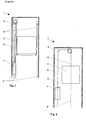
- eine Aufzugsanlage, mit Unterschlingung, mit im Aufzugsschacht befestigter Riemenendbefestigung.
- Fig. 2:
- eine Aufzugsanlage, direkt aufgehängt, mit an einer Kabine, bzw. einem Gegengewicht befestigter Riemenendbefestigung.
- Fig. 3:
- eine Riemenbefestigung, an einer Kabine bzw. an einem Gegengewicht befestigt mit nach oben wirkender Tragriemenkraft.
- Fig. 4:
- eine Riemenbefestigung, an einem Aufzugsschacht befestigt mit nach unten wirkender Tragriemenkraft.
- Fig. 5:
- Detailschnittbild einer Riemenendbefestigung.
- Fig. 5a:
- einen Querschnitt eines Tragmittels im Bereiche eines Verdrehschutzes.
- Fig. 6:
- Detail einer alternativen Riemenendbefestigung.
- Fig. 6a:
- einen Querschnitt einer Ausführungsform eines Tragmittels im Bereiche eines Verdrehschutzes.
- Fig. 7:
- Riemenendbefestigung, mit Verdrehschutz zu einer weiteren Riemenendbefestigung verbunden, am Beispiel von zwei Tragriemen (Frontansicht und Schnittdarstellung).
- Fig. 8:
- Riemenendbefestigung, mit Verdrehschutz zu einer weiteren Riemenendbefestigung verbunden, am Beispiel von vier Tragriemen.
- Fig. 1:
- an elevator installation, with underlayment, with belt end fastening fastened in the elevator shaft.
- Fig. 2:
- an elevator system, suspended directly, with a belt end fastener attached to a cab or a counterweight.
- 3:
- a belt attachment secured to a cab or to a counterweight with an upwardly acting support belt force.
- 4:
- a belt attachment, attached to a hoistway with downwardly acting support belt force.
- Fig. 5:
- Detail sectional view of a belt end fitting.
- Fig. 5a:
- a cross section of a support means in the areas of a rotation.
- Fig. 6:
- Detail of an alternative belt end fitting.
- 6a:
- a cross section of an embodiment of a support means in the areas of a rotation.
- Fig. 7:
- Belt end fastening, connected with anti-rotation protection to another belt end fastening, using the example of two carrying straps (front view and sectional view).
- Fig. 8:
- Belt end fastening, connected with anti-rotation protection to another belt end fastening, using four carrying straps as an example.
Die Aufzugsanlage 1 besteht, wie in den Fig. 1 und 2 dargestellt aus einer Kabine 3 und einem Gegengewicht 4, welche gegenläufig in einem Aufzugsschacht 2 bewegt werden. Kabine 3 und Gegengewicht 4 sind mittels Tragriemen 6 miteinander verbunden und getragen. Ein Ende des Tragriemens 6 ist mit einer Riemenendverbindung 9 an der Kabine 3, bzw. Gegengewicht 4, gemäss Fig. 2, oder im Aufzugsschacht 2, gemäss Fig. 1, befestigt. Der Ort der Befestigung richtet sich nach der Ausführungsart der Aufzugsanlage 1.
In den Fig. 3 und 4 ist ersichtlich wie der Tragriemen 6 in der Riemenendverbindung 9 mittels einem Keil 12, welcher den Tragriemen in einer Keiltasche 11 fixiert, gehalten ist. Die Riemenendbefestigung ist zur Kabine 3, bzw. dem Gegengewicht 4 oder zum Aufzugsschacht 2 verbunden.The
3 and 4 it can be seen how the carrying
Erfindungsgemäss ist wie in Fig. 5 dargestellt zur Sicherung der Riemenendverbindung 9 gegen Verdrehen ein Verdrehschutz 21 verwendet. Der Verdrehschutz 21 verhindert ein Verdrehen der Riemenendverbindung und des Tragriemens 6 um deren Längsachse zz' wirksam. Die Längsachse zz' entspricht der Wirkrichtung der Tragkraft im Tragriemen 6.According to the invention as shown in Fig. 5 for securing the
Mit dem dargestellten Verdrehschutz 21 wird ein Verdrehen der Riemenenverbindung 9 und des zugehörigen Tragriemens 6 wirksam verhindert. Einer ungleichmässigen Belastung des Tragriemens 6 oder einer Beschädigung des Tragriemens 6, wird wirksam vorgebeugt. Der Verdrehschutz 21 ist kostengünstig und er ist einfach montierbar. Er ermöglicht eine effiziente Kontrolle des Zustandes der Riemenendverbindung 9 und verbessert damit deren Verfügbarkeit.With the illustrated anti-rotation 21 twisting the
In einer vorteilhaften Ausführung ist der Verdrehschutz 21 ein Flachprofil 22, wie in den Fig. 5, 7 und 8 beispielhaft dargestellt. Das Flachprofil ist beispielsweise ein Stahlblechstreifen. Das Flachprofil 22 ist im dargestellten Beispiel, in der Nähe der Riemenendverbindung 9, in flächigem Kontakt mit dem Tragriemen 6, angeordnet.In an advantageous embodiment, the anti-rotation 21 is a flat profile 22, as shown in FIGS. 5, 7 and 8 by way of example. The flat profile is for example a sheet steel strip. The flat profile 22 is arranged in the illustrated example, in the vicinity of the
Der Vorteil dieser Ausführung ist die besonders kostengünstige Herstellung des Verdrehschutzes 21 und der gesamten Riemenendverbindung 9. Es können einfach gestaltete Teile verwendet werden, welche kein spezifisches Fertigungswissen verlangen.The advantage of this design is the particularly cost-effective production of the anti-rotation 21 and the
Wie in Fig. 5 ersichtlich wird der Verdrehschutz 21 zwischen einem tragenden Trumm 8 des Tragriemens 6 und losem Trumm 7 des Tragriemens 6 befestigt. Diese Ausführung ist vorteilhaft da mit lediglich einem einfach geformten Verdrehschutz 21 ein Schutz gegen Verdrehen erreicht wird. Dies ist kostengünstig. Alternativ kann wie in Fig. 6 dargestellt der Verdrehschutz 21 ausserhalb des tragenden und / oder losen Trumms 7,8 des Tragriemens 6 angeordnet sein. Mit dieser Ausführung ist beispielsweise eine Nachrüstung eines Verdrehschutzes in einer bestehenden Aufzugsanlage 1 einfach möglich.
Selbstverständlich kann ein speziell geformter Verdrehschutz 21 den Tragriemen 6 auch umfassen. Damit werden besondere Anpassungen an die örtlichen Befestigungsmöglichkeiten ermöglicht.As shown in Fig. 5, the anti-rotation 21 between a supporting Trumm 8 of the
Of course, a specially shaped anti-rotation 21 may also include the
Der Verdrehschutz 21 kann zwei Tragriemen 6 miteinander verbinden und / oder er kann einen oder mehrere Tragriemen 6 mit einem Teil der Aufzugsanlage verbinden. Die Riemenendverbindung 9 ist somit, direkt oder indirekt, mit mindestens einer weiteren Riemenendverbindung und / oder mit einem Teil der Aufzugsanlage verbunden. Eine direkte Verbindung kann erfolgen, indem der Verdrehschutz 21 beispielsweise an einem die Keiltasche 11 umfassendem Keilgehäuse 10 angeordnet wird. Eine indirekte Verbindung kann erfolgen indem der Verdrehschutz 21 beispielsweise an dem Tragriemen 6 angeordnet wird.The anti-rotation 21 can connect two
Die Verbindungsanordnungen erlauben die Auswahl der jeweils kostengünstigsten und / oder Platz sparendsten Anordnung. Die Verbindung zweier Tragriemen 6 ist dabei besonders effizient, da keine weiteren Teile oder Anschlusspunkte benötigt werden.The connection arrangements allow the selection of the most cost-effective and / or space-saving arrangement. The connection of two
In einer besonderen Ausführung ist der Verdrehschutz 21 geformt. Es ermöglicht dadurch den Anschluss an einen Teil der Aufzugsanlage oder die Umgehung eines Aufzugsteiles, wie beispielsweise einen Träger oder eine Führungsschiene 5. In Fig. 7 ist ein Beispiel dargestellt bei dem ein Verdrehschutz 21 in der Form eines Flachprofils 22 aus Stahlblech, zwei Riemenendverbindungen 9 miteinander verbindet und dadurch ein Verdrehen beider Riemenendverbindungen 9 verhindert. Der Verdrehschutz 21 ist dabei derart geformt, dass er die Führungsschiene 5 umgeht.
In Fig. 8 ist ein weiterer besonders einfacher Verdrehschutz dargestellt, welcher vier Riemenendbefestigungen 9 gegen verdrehen schützt indem jeweils zwei Riemenendbefestigungen 9 miteinander verbunden sind.
Die gezeigten Ausführungen berücksichtigen die speziellen Anordnungen der Aufzugsanlage. Sie sind besonders einfach und kostengünstig, da mit einem Verdrehschutz 21 mehrere Riemenendbefestigungen 9 gesichert werden können oder besonders einfache Formen von Verdrehschützen 21 verwendbar sind.In a particular embodiment, the anti-rotation 21 is formed. It thereby enables the connection to a part of the elevator installation or the bypass of an elevator part, such as a support or a
In Fig. 8, a further particularly simple anti-rotation protection is shown, which protects four
The embodiments shown take into account the special arrangements of the elevator installation. They are particularly simple and cost-effective, since a plurality of
Wie in den Fig. 5 bis 8 als vorteilhafte Lösungen dargestellt ist zur Befestigung des Verdrehschutzes 21 jeweils ein Kabelbinder 23 verwendet. Der Kabelbinder 23 ist hierbei durch eine Öffnung im Verdrehschutz 21 geführt. Weitere Kabelbinder 23 sind in den gezeigten Ausführungen verwendet um den losen Trumm 7 des Tragmittels 6 zu fixieren.
Kabelbinder 23 sind kostengünstige Bauteile, welche einfach beschafft werden können. Die dargestellte Ausführung ist dementsprechend kostengünstig und einfach bereitzustellen. Zudem ermöglicht die dargestellte Ausführung geringfügige Verschiebungen zwischen mehreren miteinander verbundenen Riememendverbindungen 9, wie sie sich beispielsweise bei unterschiedlichen Dehnungen der Tragriemen 6 ergeben können.As shown in FIGS. 5 to 8 as advantageous solutions, a
Cable ties 23 are inexpensive components that can be easily procured. The illustrated embodiment is accordingly inexpensive and easy to provide. In addition, the illustrated embodiment allows slight displacements between a plurality of interconnected
Gemäss einem weiteren Teil der Erfindung ist der Keil 12, welcher den Tragriemen 6 in der Keiltasche 11 der Riemenendverbindung 9 fixiert, wie in Fig. 5 gezeigt, mittels einem Verlierschutz 19 gesichert. Der Verlierschutz 19 ist im Bedarfsfalle einfach entfernbar.
Der Verlierschutz 19 verhindert wirksam, dass der Keil 12 im Falle von losen Tragriemen 6 herausrutschen kann. Lose Tragriemen 6 können sich ergeben, wenn die Kabine 3 oder das Gegengewicht 4 stark bremst oder abgebremst wird, was beispielsweise bei einem Test von Sicherheitsbremsen oder bei einem Auffahren von Kabine 3 oder Gegengewicht 4 auf Fahrwegbegrenzungseinrichtungen - beispielsweise Auffahrpuffer - erfolgen kann.
Einer Beschädigung des Tragriemens 6, bzw. der Riemenendverbindung 9 durch Verschiebung oder Verklemmung oder Herausrutschen des Keiles 12 wird dadurch wirksam vorgebeugt. Der dargestellte Verlierschutz 19 ist zudem einfach montier- und demontierbar.According to another part of the invention, the
The
Damage to the
In einer vorteilhaften Ausführung ist der Verlierschutz 19 zusammen mit einer Tragbolzensicherung 20 befestigt. Als Tragbolzensicherung 20 ist dabei beispielsweise ein Splint verwendet. Eine Tragbolzensicherung 20 ist in der Regel erforderlich um ein Ausdrehen eines Tragbolzens 17 zu verhindern. Der Tragbolzen 17 überträgt die Tragkraft des Tragriemens 6 vom Keilgehäuse 10 zur Kabine 3, bzw. zum Gegengewicht 4 oder zum Aufzugsschacht 2. Mit der dargestellten Lösung können zwei Forderungen - Schutz gegen Herausrutschen des Keiles und verhindern des Ausdrehen des Tragbolzen - gemeinsam erfüllt werden. Dies ist besonders kosten- und montagegünstig.In an advantageous embodiment of the
Der Tragbolzen 17 ist vorteilhafterweise als Gewindebolzen 18 ausgeführt. Damit lässt sich eine sichere und kostengünstige Einleitung der Tragkräfte in den Aufzugsschacht 2, die Kabine 3 oder das Gegengewicht 4 erreichen.The support pin 17 is advantageously designed as a threaded bolt 18. This allows a safe and cost-effective introduction of the load-bearing forces in the
Fig. 5a, 6a zeigen schematische Querschnitte von beispielhaften Tragriemen 6. Der Tragriemen 6 ist gemäss den Trag- und Treibfähigkeitsanforderungen hergestellt. Er besteht in der Regel aus mindestens zwei, bzw. mehreren in einem Abstand zueinander angeordneten Seillitzen 6a und einem Mantel 6b, der die Seillitzen 6a voneinander trennt und umschliesst. In einer anderen Variante besteht der Tragriemen 6 aus zwei oder mehreren in einem Abstand zueinander angeordneten Seilen 6a und einem Mantel 6b, welcher die einzelnen Seile 6a voneinander trennt und umschliesst. Als Mantelmaterial sind im wesentlichen Thermoplaste oder Elastomere verwendet. Eine Breite des entsprechenden Tragriemens 6 entspricht mindestens einer zweifachen Höhe des Riemens. Der Mantel 6b des Tragriemens weist eine Funktionsgerechte Formgebung auf. Er ist beispielsweise, wie in Fig. 5a dargestellt, entsprechend der Seilform ausgeprägt, wodurch sich Längsrillen ergeben oder er weist, wie in Fig. 5b ersichtlich, eine Funktionsoberfläche in der Form von Längs- oder Querrillen auf. Der Mantel 6b ist dazu ausgelegt die zum Antreiben eines Aufzuges erforderlichen Treibkräfte von einer Treibscheibe in die tragenden Seile oder Seillitzen 6a zu übertragen und er muss im wesentlichen innerhalb der Riemenendverbindung 9 eine im Tragriemen 6 wirkende Tragkraft von den Seilen oder den Seillitzen 6a zur Riemenendverbindung 9 übertragen. Das Seil oder die Seillitzen 6a bestehen vorzugsweise aus metallischem Werkstoff wie z.B. Stahl oder sie bestehen aus Kunststofffasern.5a, 6a show schematic cross sections of exemplary carrying
Bei Kenntnis der vorliegenden Erfindung kann der Aufzugsfachmann die gesetzten Formen und Anordnungen beliebig verändern. So kann er beispielsweise anstelle des Kabelbinders 23 andere Befestigungen, wie eine Klemme oder Draht, usw. verwenden. Weitere Variationen sind möglich.With knowledge of the present invention, the elevator expert can arbitrarily change the set shapes and arrangements. For example, instead of the
Claims (14)
ein Verdrehschutz (21) vorgesehen ist, welcher ein Verdrehen der Riemenendverbindung (9) um deren Längsachse (zz') verhindert.Riemenendverbindung for fastening one end of a support belt in an elevator system, characterized in that
a rotation protection (21) is provided, which prevents rotation of the Riemenendverbindung (9) about its longitudinal axis (zz ').
der Verdrehschutz (21) zwischen tragendem und losem Trumm (8, 7) des Tragriemens (6) befestigt ist oder, dass der Tragriemen (6) zwischen zwei Verdrehschützen (21) befestigt ist oder, dass der Tragriemen (6) von einem geformten Verdrehschutz (21) umfasst ist.Riemenendverbindung according to one of the preceding claims, characterized in that
the anti-rotation device (21) is fastened between the carrying and loose run (8, 7) of the carrying strap (6) or that the carrying strap (6) is fastened between two anti-rotation guards (21) or that the carrying strap (6) is formed by a molded anti-twist device (21) is included.
der Verdrehschutz (21) mindestens zwei Tragriemen (6) miteinander verbindet und / oder, dass der Verdrehschutz (21) ein oder mehrere Tragriemen (6) mit einem Teil der Aufzugsanlage verbindet.Riemenendverbindung according to one of the preceding claims, characterized in that
the anti-twist device (21) connects at least two carrying straps (6) to one another and / or that the anti-twist device (21) connects one or more carrying straps (6) to a part of the elevator system.
der Verdrehschutz (21) geformt ist um den Anschluss an einen Teil der Aufzugsanlage zu ermöglichen oder um einen Teil der Aufzugsanlage zu umgehen.Riemenendverbindung according to one of the preceding claims, characterized in that
the twist protection (21) is shaped to allow connection to a part of the elevator installation or to bypass a part of the elevator installation.
zur Befestigung des Verdrehschutzes (21) ein Kabelbinder (23) verwendet ist.Riemenendverbindung according to one of the preceding claims, characterized in that
for fastening the anti-rotation device (21) a cable tie (23) is used.
der Keil (12) mittels eines Verlierschutzes (19) gegen Herausrutschen aus der Keiltasche (11) gesichert ist.Belt end connection for fastening one end of a support belt in an elevator installation, wherein the support belt (6) is held in a wedge pocket (11) by means of a wedge (12), characterized in that
the wedge (12) by means of a Verlierschutzes (19) against slipping out of the wedge pocket (11) is secured.
der Tragriemen (6) aus mindestens zwei in einem Abstand zueinander angeordneten Seilen oder Seillitzen (6a) und einem Mantel (6b), welcher die einzelnen Seile oder Seillitzen (6a) voneinander trennt und umschliesst, besteht, der Seilmantel (6b) aus Thermoplast oder einem Elastomer besteht und
eine Breite des Tragriemens (6) mindestens einer zweifachen Höhe des Tragriemens (6) entspricht.Riemenendverbindung according to one of the preceding claims, characterized in that
the carrying strap (6) consists of at least two ropes or rope strands (6a) arranged at a distance from one another and a sheath (6b) which separates and encloses the individual ropes or rope strands (6a), the rope sheath (6b) consists of thermoplastic material or consists of an elastomer and
a width of the support belt (6) corresponds to at least twice the height of the support belt (6).
ein Verdrehschutz (21) zum Schutze gegen Verdrehen der Riemenendverbindung (9) um deren Längsachse (zz') vorgesehen wird.Method for protecting a belt end connection, which is used for fastening an end of a support belt in an elevator installation, characterized in that
a twist protection (21) to protect against rotation of the Riemenendverbindung (9) about its longitudinal axis (zz ') is provided.
der Keil (12) mittels eines Verlierschutzes (19) gegen Herausrutschen aus der Keiltasche (11) gesichert wird.Method for protecting a belt end connection, which is used for fastening one end of a support belt in an elevator installation, wherein the support belt (6) is held in a wedge pocket (11) by means of a wedge (12), characterized in that
the wedge (12) by means of a Verlierschutzes (19) against slipping out of the wedge pocket (11) is secured.
ein Verdrehschutz (21) zur Kontrolle einer korrekten Zugspannung der Tragriemen (6) verwendet wird.Method for testing which is used for fixing one end of a support belt in a lift installation a belt end, characterized, in that
a Verdrehschutz (21) is used to control a correct tension of the strap (6).
ein Verlierschutz (19) zur Kontrolle des korrekten Sitzes des Keiles (12) in der Keiltasche (11) verwendet wird.Method for testing a belt end connection, which is used for fastening one end of a support belt in an elevator installation, wherein the support belt (6) is held in a wedge pocket (11) by means of a wedge (12), characterized in that
a loss guard (19) is used to check the correct seating of the wedge (12) in the wedge pocket (11).
Priority Applications (1)
| Application Number | Priority Date | Filing Date | Title |
|---|---|---|---|
| EP05108148A EP1634842A3 (en) | 2004-09-13 | 2005-09-06 | Wedge clamp for belt driven elevator |
Applications Claiming Priority (2)
| Application Number | Priority Date | Filing Date | Title |
|---|---|---|---|
| EP04021670 | 2004-09-13 | ||
| EP05108148A EP1634842A3 (en) | 2004-09-13 | 2005-09-06 | Wedge clamp for belt driven elevator |
Publications (2)
| Publication Number | Publication Date |
|---|---|
| EP1634842A2 true EP1634842A2 (en) | 2006-03-15 |
| EP1634842A3 EP1634842A3 (en) | 2009-02-18 |
Family
ID=34926508
Family Applications (1)
| Application Number | Title | Priority Date | Filing Date |
|---|---|---|---|
| EP05108148A Pending EP1634842A3 (en) | 2004-09-13 | 2005-09-06 | Wedge clamp for belt driven elevator |
Country Status (12)
| Country | Link |
|---|---|
| US (2) | US7469774B2 (en) |
| EP (1) | EP1634842A3 (en) |
| JP (1) | JP5096670B2 (en) |
| CN (1) | CN100540437C (en) |
| AR (1) | AR050738A1 (en) |
| AU (1) | AU2005209671B2 (en) |
| BR (1) | BRPI0503823B1 (en) |
| CA (2) | CA2518660C (en) |
| NO (1) | NO341752B1 (en) |
| NZ (1) | NZ542101A (en) |
| RU (1) | RU2383487C2 (en) |
| ZA (1) | ZA200506660B (en) |
Cited By (4)
| Publication number | Priority date | Publication date | Assignee | Title |
|---|---|---|---|---|
| WO2019034405A1 (en) | 2017-08-17 | 2019-02-21 | Inventio Ag | Elevator system |
| WO2020164965A1 (en) | 2019-02-12 | 2020-08-20 | Inventio Ag | Lift system |
| WO2020164966A1 (en) | 2019-02-12 | 2020-08-20 | Inventio Ag | Lift system |
| WO2020173798A1 (en) | 2019-02-28 | 2020-09-03 | Inventio Ag | Lift system |
Families Citing this family (16)
| Publication number | Priority date | Publication date | Assignee | Title |
|---|---|---|---|---|
| ATE484357T1 (en) * | 2004-03-15 | 2010-10-15 | Otis Elevator Co | METHOD FOR PRODUCING A LOAD-BEARING LIMB FOR ELEVATOR SYSTEMS HAVING A SHELL WITH AT LEAST ONE ROUGH OUTER SURFACE |
| ES2319911T3 (en) * | 2004-09-13 | 2009-05-14 | Inventio Ag | CONNECTION OF END OF SUSPENSION MEDIUM TO SET AN EXTREME OF A SUSPENSION MEDIUM IN AN ELEVATOR INSTALLATION AND PROCEDURE FOR FIXING AN EXTREME OF A SUSPENSION MEDIA IN AN ELEVATOR INSTALLATION. |
| EP1860054B1 (en) * | 2006-05-03 | 2013-04-17 | Inventio AG | Elevator with carrier and traction means |
| CN101066734B (en) * | 2006-05-03 | 2010-09-01 | 因温特奥股份公司 | Elevator with carrier and traction means |
| ES2294944B1 (en) * | 2006-09-25 | 2009-02-16 | Orona S. Coop | SUSPENSION AND TRACTION ELEMENT FOR LIFTING AND LIFTING EQUIPMENT. |
| EP2000431A1 (en) * | 2007-06-04 | 2008-12-10 | Inventio Ag | Terminal connector and method for attaching a belt-like load carrier of a lift system |
| US9233508B2 (en) * | 2008-11-17 | 2016-01-12 | Hall Inc. | Rigging, rigging terminals, and methods of assembling rigging and rigging terminals for a sailboat |
| US8375527B1 (en) | 2009-08-07 | 2013-02-19 | The Crosby Group, Inc. | Actuated wedge socket assembly |
| GB2476655B (en) * | 2009-12-30 | 2014-03-19 | Jdr Cable Systems Ltd | Cable termination system |
| CN102011834A (en) * | 2010-11-02 | 2011-04-13 | 国家海洋局南海工程勘察中心 | Wearproof loosing-preventing rope connecting element for measurement buoy |
| JP5447885B2 (en) * | 2012-02-09 | 2014-03-19 | 東芝エレベータ株式会社 | Elevator equipment |
| WO2014083043A1 (en) * | 2012-11-29 | 2014-06-05 | Inventio Ag | Elevator system |
| EP2878563B1 (en) * | 2013-11-29 | 2017-03-22 | KONE Corporation | A rope terminal assembly and an elevator |
| EP3248926A1 (en) * | 2016-05-24 | 2017-11-29 | KONE Corporation | Elevator arrangement and method |
| CN108147254B (en) * | 2016-12-02 | 2020-12-01 | 奥的斯电梯公司 | Elevator system suspension member termination with improved pressure distribution |
| US12038066B2 (en) * | 2022-01-31 | 2024-07-16 | Gates Corporation | Clamp for flat belts |
Family Cites Families (19)
| Publication number | Priority date | Publication date | Assignee | Title |
|---|---|---|---|---|
| US2234028A (en) * | 1940-04-05 | 1941-03-04 | Illinois Malleable Iron Co | Clamp |
| US2827680A (en) * | 1955-07-21 | 1958-03-25 | Gibson Jack | Wedge-eye cable anchoring devices |
| US3666051A (en) * | 1970-08-06 | 1972-05-30 | Nasa | Cable stabilizer for open shaft cable operated elevators |
| US4724929A (en) * | 1982-08-04 | 1988-02-16 | Siecor Corporation | Elevator compensating cable |
| JPH0416478A (en) * | 1990-05-07 | 1992-01-21 | Mitsubishi Electric Corp | Rope locking device for elevator |
| JPH04125282A (en) | 1990-09-14 | 1992-04-24 | Hitachi Ltd | Elevator device |
| US5199137A (en) * | 1991-03-25 | 1993-04-06 | Nylube Products, Co. | Rope guard assembly for wedge clamp |
| US5353893A (en) * | 1993-07-12 | 1994-10-11 | Otis Elevator Company | Elevator cab and/or counterweight compensation rope hitch assembly |
| JPH07172733A (en) | 1993-12-20 | 1995-07-11 | Mitsubishi Denki Bill Techno Service Kk | Rope socket detent jig for main rope and tension adjusting method for main rope |
| JPH07224909A (en) * | 1994-02-10 | 1995-08-22 | Mitsubishi Denki Bill Techno Service Kk | Locking jig of simple rod |
| US5553360A (en) * | 1995-05-19 | 1996-09-10 | The Crosby Group, Inc. | Extended wedge socket assembly |
| US6256841B1 (en) * | 1998-12-31 | 2001-07-10 | Otis Elevator Company | Wedge clamp type termination for elevator tension member |
| JP2000086114A (en) * | 1998-09-14 | 2000-03-28 | Toshiba Corp | Elevator |
| US6484368B1 (en) * | 2000-01-11 | 2002-11-26 | Otis Elevator Company | Flexible flat tension member termination device |
| US6345419B1 (en) | 2000-01-19 | 2002-02-12 | Otis Elevator Company | Termination for flat flexible tension member |
| US6994487B2 (en) * | 2001-04-18 | 2006-02-07 | Otis Elevator Company | Elevator load bearing termination assembly |
| US6662408B2 (en) * | 2001-09-07 | 2003-12-16 | Otis Elevator Company | Elevator load bearing termination assembly with gripping inserts |
| JP2006513950A (en) | 2003-01-31 | 2006-04-27 | オーチス エレベータ カンパニー | Integrated support for elevator machines, sheaves and terminations |
| JP2007031148A (en) * | 2005-07-22 | 2007-02-08 | Inventio Ag | Support means end connection part for fastening end of support means in elevator device, elevator device having support means end connection part and method of fastening end of support means in elevator device |
-
2005
- 2005-08-19 ZA ZA200506660A patent/ZA200506660B/en unknown
- 2005-08-26 JP JP2005245380A patent/JP5096670B2/en not_active Expired - Fee Related
- 2005-08-29 NZ NZ542101A patent/NZ542101A/en unknown
- 2005-08-31 US US11/216,400 patent/US7469774B2/en active Active
- 2005-09-06 EP EP05108148A patent/EP1634842A3/en active Pending
- 2005-09-09 CA CA2518660A patent/CA2518660C/en active Active
- 2005-09-09 CA CA2783219A patent/CA2783219C/en not_active Expired - Fee Related
- 2005-09-12 NO NO20054226A patent/NO341752B1/en unknown
- 2005-09-12 AR ARP050103801A patent/AR050738A1/en not_active Application Discontinuation
- 2005-09-12 RU RU2005128360/11A patent/RU2383487C2/en active
- 2005-09-12 AU AU2005209671A patent/AU2005209671B2/en active Active
- 2005-09-13 CN CNB2005100995152A patent/CN100540437C/en active Active
- 2005-09-13 BR BRPI0503823A patent/BRPI0503823B1/en active IP Right Grant
-
2008
- 2008-10-29 US US12/260,309 patent/US7740113B2/en active Active
Non-Patent Citations (1)
| Title |
|---|
| None * |
Cited By (8)
| Publication number | Priority date | Publication date | Assignee | Title |
|---|---|---|---|---|
| WO2019034405A1 (en) | 2017-08-17 | 2019-02-21 | Inventio Ag | Elevator system |
| WO2019034381A1 (en) | 2017-08-17 | 2019-02-21 | Inventio Ag | Elevator system |
| US11535493B2 (en) | 2017-08-17 | 2022-12-27 | Inventio Ag | Elevator system |
| US11623845B2 (en) | 2017-08-17 | 2023-04-11 | Inventio Ag | Elevator system |
| WO2020164965A1 (en) | 2019-02-12 | 2020-08-20 | Inventio Ag | Lift system |
| WO2020164966A1 (en) | 2019-02-12 | 2020-08-20 | Inventio Ag | Lift system |
| US11807497B2 (en) | 2019-02-12 | 2023-11-07 | Inventio Ag | Elevator system |
| WO2020173798A1 (en) | 2019-02-28 | 2020-09-03 | Inventio Ag | Lift system |
Also Published As
| Publication number | Publication date |
|---|---|
| EP1634842A3 (en) | 2009-02-18 |
| US7469774B2 (en) | 2008-12-30 |
| AU2005209671B2 (en) | 2011-07-14 |
| CA2518660C (en) | 2013-05-14 |
| NZ542101A (en) | 2007-02-23 |
| AU2005209671A1 (en) | 2006-03-30 |
| RU2383487C2 (en) | 2010-03-10 |
| CA2783219A1 (en) | 2006-03-13 |
| RU2005128360A (en) | 2007-03-20 |
| CA2783219C (en) | 2015-01-13 |
| US7740113B2 (en) | 2010-06-22 |
| ZA200506660B (en) | 2006-05-31 |
| JP2006076791A (en) | 2006-03-23 |
| US20090127032A1 (en) | 2009-05-21 |
| BRPI0503823A (en) | 2007-05-22 |
| BRPI0503823B1 (en) | 2019-12-17 |
| NO20054226D0 (en) | 2005-09-12 |
| US20060054468A1 (en) | 2006-03-16 |
| AR050738A1 (en) | 2006-11-15 |
| JP5096670B2 (en) | 2012-12-12 |
| NO20054226L (en) | 2006-03-14 |
| CN100540437C (en) | 2009-09-16 |
| CN1749143A (en) | 2006-03-22 |
| NO341752B1 (en) | 2018-01-15 |
| CA2518660A1 (en) | 2006-03-13 |
Similar Documents
| Publication | Publication Date | Title |
|---|---|---|
| EP1634842A2 (en) | Wedge clamp for belt driven elevator | |
| EP2141110B1 (en) | Lift load-bearing mechanism for a lift system, lift system with such a lift load-bearing mechanism and method for assembly of such a lift system | |
| EP1777189A1 (en) | Carrying means device comprising a traction sheave and carrying means as well as an elevator comprising said carrying means device | |
| EP2928805A1 (en) | Double-decker lift with adjustable inter-car spacing | |
| EP1790608B1 (en) | Elevator system comprising a device for compensating the difference of weight between the section of the carrying means on the car side and on the counterweight side and method for creating said compensation | |
| WO2015058909A1 (en) | Fastening device for fastening a step or a pallet to a traction mechanism | |
| EP2859245A1 (en) | Lift system | |
| WO2010052076A1 (en) | Tractive drive and lift installation comprising said tractive drive | |
| EP0787676A1 (en) | Safety device | |
| EP1067010B1 (en) | Pulley assembly for tensioning apparatus for conductors and supporting wires in a catenary overhead wire system | |
| EP2918482A2 (en) | Traction chain for a track chain of a tracked vehicle and kit for a track chain | |
| CH653299A5 (en) | DEVICE FOR THE ELASTIC ARRANGEMENT OF A WHEEL ON A WHEEL HUB FOR CHASSIS VEHICLES. | |
| DE112009004904B4 (en) | Drive arrangement for a passenger conveyor | |
| EP1026115B1 (en) | Cable retainer for lifts | |
| EP1669315A1 (en) | Method and emergency drive device for driving an elevator car | |
| DE202020104953U1 (en) | Device for securing a shuttle, shuttle and shelving system | |
| DE10200874A1 (en) | Lift for people and or freight has cage driven by drive unit with drive wheel, power transmission unit, chain with links and shaft | |
| DE20301358U1 (en) | Escalator or moving walk | |
| DE102007015825A1 (en) | Drive for lifts in self-supporting design | |
| AT409254B (en) | ROLLER ROLL FOR THE CHASSIS OF THE DRIVING EQUIPMENT OF A ROPEWAY SYSTEM | |
| DE4036036A1 (en) | Safety device for lift - has safety cable in two parts connected by clamp to reduce magnitude of force applied to cable | |
| EP3020674B1 (en) | Service lift | |
| EP0646518B1 (en) | Track for tracked vehicles, especially snow vehicles | |
| DE102020122390A1 (en) | Device for securing a shuttle, shuttle and shelving system | |
| DE4111379A1 (en) | CONVEYOR DEVICE ON ROPE CONVEYOR SYSTEMS FOR DRIVING CONVEYOR ROPES |
Legal Events
| Date | Code | Title | Description |
|---|---|---|---|
| PUAI | Public reference made under article 153(3) epc to a published international application that has entered the european phase |
Free format text: ORIGINAL CODE: 0009012 |
|
| AK | Designated contracting states |
Kind code of ref document: A2 Designated state(s): AT BE BG CH CY CZ DE DK EE ES FI FR GB GR HU IE IS IT LI LT LU LV MC NL PL PT RO SE SI SK TR |
|
| AX | Request for extension of the european patent |
Extension state: AL BA HR MK YU |
|
| REG | Reference to a national code |
Ref country code: HK Ref legal event code: DE Ref document number: 1089740 Country of ref document: HK |
|
| PUAL | Search report despatched |
Free format text: ORIGINAL CODE: 0009013 |
|
| AK | Designated contracting states |
Kind code of ref document: A3 Designated state(s): AT BE BG CH CY CZ DE DK EE ES FI FR GB GR HU IE IS IT LI LT LU LV MC NL PL PT RO SE SI SK TR |
|
| AX | Request for extension of the european patent |
Extension state: AL BA HR MK YU |
|
| 17P | Request for examination filed |
Effective date: 20090729 |
|
| AKX | Designation fees paid |
Designated state(s): AT BE BG CH CY CZ DE DK EE ES FI FR GB GR HU IE IS IT LI LT LU LV MC NL PL PT RO SE SI SK TR |
|
| 17Q | First examination report despatched |
Effective date: 20091009 |
|
| STAA | Information on the status of an ep patent application or granted ep patent |
Free format text: STATUS: EXAMINATION IS IN PROGRESS |
|
| STAA | Information on the status of an ep patent application or granted ep patent |
Free format text: STATUS: EXAMINATION IS IN PROGRESS |
|
| RAP3 | Party data changed (applicant data changed or rights of an application transferred) |
Owner name: INVENTIO AG |