EP1634786A2 - Bremsservosteuereinheit, -Verfahren, und -Fahrzeug - Google Patents
Bremsservosteuereinheit, -Verfahren, und -Fahrzeug Download PDFInfo
- Publication number
- EP1634786A2 EP1634786A2 EP05025476A EP05025476A EP1634786A2 EP 1634786 A2 EP1634786 A2 EP 1634786A2 EP 05025476 A EP05025476 A EP 05025476A EP 05025476 A EP05025476 A EP 05025476A EP 1634786 A2 EP1634786 A2 EP 1634786A2
- Authority
- EP
- European Patent Office
- Prior art keywords
- pressure
- master cylinder
- current
- time
- control
- Prior art date
- Legal status (The legal status is an assumption and is not a legal conclusion. Google has not performed a legal analysis and makes no representation as to the accuracy of the status listed.)
- Granted
Links
- 238000000034 method Methods 0.000 title claims abstract description 14
- 230000007423 decrease Effects 0.000 claims abstract description 32
- 230000007246 mechanism Effects 0.000 claims abstract description 31
- 230000003247 decreasing effect Effects 0.000 claims description 14
- 230000006870 function Effects 0.000 abstract description 30
- 239000007788 liquid Substances 0.000 abstract description 11
- 238000006243 chemical reaction Methods 0.000 description 18
- 230000007704 transition Effects 0.000 description 10
- 230000008859 change Effects 0.000 description 9
- 230000008569 process Effects 0.000 description 5
- 238000010586 diagram Methods 0.000 description 4
- 230000003044 adaptive effect Effects 0.000 description 3
- 230000005540 biological transmission Effects 0.000 description 3
- 238000001514 detection method Methods 0.000 description 2
- 230000010354 integration Effects 0.000 description 2
- 230000009467 reduction Effects 0.000 description 2
- 230000003068 static effect Effects 0.000 description 2
- 201000007224 Myeloproliferative neoplasm Diseases 0.000 description 1
- 230000006399 behavior Effects 0.000 description 1
- 238000006073 displacement reaction Methods 0.000 description 1
- 230000005489 elastic deformation Effects 0.000 description 1
- 238000004092 self-diagnosis Methods 0.000 description 1
- 230000001052 transient effect Effects 0.000 description 1
Images


Classifications
-
- B—PERFORMING OPERATIONS; TRANSPORTING
- B60—VEHICLES IN GENERAL
- B60T—VEHICLE BRAKE CONTROL SYSTEMS OR PARTS THEREOF; BRAKE CONTROL SYSTEMS OR PARTS THEREOF, IN GENERAL; ARRANGEMENT OF BRAKING ELEMENTS ON VEHICLES IN GENERAL; PORTABLE DEVICES FOR PREVENTING UNWANTED MOVEMENT OF VEHICLES; VEHICLE MODIFICATIONS TO FACILITATE COOLING OF BRAKES
- B60T13/00—Transmitting braking action from initiating means to ultimate brake actuator with power assistance or drive; Brake systems incorporating such transmitting means, e.g. air-pressure brake systems
- B60T13/10—Transmitting braking action from initiating means to ultimate brake actuator with power assistance or drive; Brake systems incorporating such transmitting means, e.g. air-pressure brake systems with fluid assistance, drive, or release
- B60T13/24—Transmitting braking action from initiating means to ultimate brake actuator with power assistance or drive; Brake systems incorporating such transmitting means, e.g. air-pressure brake systems with fluid assistance, drive, or release the fluid being gaseous
- B60T13/46—Vacuum systems
- B60T13/52—Vacuum systems indirect, i.e. vacuum booster units
-
- B—PERFORMING OPERATIONS; TRANSPORTING
- B60—VEHICLES IN GENERAL
- B60T—VEHICLE BRAKE CONTROL SYSTEMS OR PARTS THEREOF; BRAKE CONTROL SYSTEMS OR PARTS THEREOF, IN GENERAL; ARRANGEMENT OF BRAKING ELEMENTS ON VEHICLES IN GENERAL; PORTABLE DEVICES FOR PREVENTING UNWANTED MOVEMENT OF VEHICLES; VEHICLE MODIFICATIONS TO FACILITATE COOLING OF BRAKES
- B60T13/00—Transmitting braking action from initiating means to ultimate brake actuator with power assistance or drive; Brake systems incorporating such transmitting means, e.g. air-pressure brake systems
- B60T13/10—Transmitting braking action from initiating means to ultimate brake actuator with power assistance or drive; Brake systems incorporating such transmitting means, e.g. air-pressure brake systems with fluid assistance, drive, or release
- B60T13/66—Electrical control in fluid-pressure brake systems
- B60T13/72—Electrical control in fluid-pressure brake systems in vacuum systems or vacuum booster units
-
- B—PERFORMING OPERATIONS; TRANSPORTING
- B60—VEHICLES IN GENERAL
- B60T—VEHICLE BRAKE CONTROL SYSTEMS OR PARTS THEREOF; BRAKE CONTROL SYSTEMS OR PARTS THEREOF, IN GENERAL; ARRANGEMENT OF BRAKING ELEMENTS ON VEHICLES IN GENERAL; PORTABLE DEVICES FOR PREVENTING UNWANTED MOVEMENT OF VEHICLES; VEHICLE MODIFICATIONS TO FACILITATE COOLING OF BRAKES
- B60T17/00—Component parts, details, or accessories of power brake systems not covered by groups B60T8/00, B60T13/00 or B60T15/00, or presenting other characteristic features
- B60T17/18—Safety devices; Monitoring
- B60T17/22—Devices for monitoring or checking brake systems; Signal devices
- B60T17/221—Procedure or apparatus for checking or keeping in a correct functioning condition of brake systems
-
- B—PERFORMING OPERATIONS; TRANSPORTING
- B60—VEHICLES IN GENERAL
- B60T—VEHICLE BRAKE CONTROL SYSTEMS OR PARTS THEREOF; BRAKE CONTROL SYSTEMS OR PARTS THEREOF, IN GENERAL; ARRANGEMENT OF BRAKING ELEMENTS ON VEHICLES IN GENERAL; PORTABLE DEVICES FOR PREVENTING UNWANTED MOVEMENT OF VEHICLES; VEHICLE MODIFICATIONS TO FACILITATE COOLING OF BRAKES
- B60T7/00—Brake-action initiating means
- B60T7/12—Brake-action initiating means for automatic initiation; for initiation not subject to will of driver or passenger
-
- B—PERFORMING OPERATIONS; TRANSPORTING
- B60—VEHICLES IN GENERAL
- B60T—VEHICLE BRAKE CONTROL SYSTEMS OR PARTS THEREOF; BRAKE CONTROL SYSTEMS OR PARTS THEREOF, IN GENERAL; ARRANGEMENT OF BRAKING ELEMENTS ON VEHICLES IN GENERAL; PORTABLE DEVICES FOR PREVENTING UNWANTED MOVEMENT OF VEHICLES; VEHICLE MODIFICATIONS TO FACILITATE COOLING OF BRAKES
- B60T8/00—Arrangements for adjusting wheel-braking force to meet varying vehicular or ground-surface conditions, e.g. limiting or varying distribution of braking force
- B60T8/32—Arrangements for adjusting wheel-braking force to meet varying vehicular or ground-surface conditions, e.g. limiting or varying distribution of braking force responsive to a speed condition, e.g. acceleration or deceleration
- B60T8/34—Arrangements for adjusting wheel-braking force to meet varying vehicular or ground-surface conditions, e.g. limiting or varying distribution of braking force responsive to a speed condition, e.g. acceleration or deceleration having a fluid pressure regulator responsive to a speed condition
- B60T8/36—Arrangements for adjusting wheel-braking force to meet varying vehicular or ground-surface conditions, e.g. limiting or varying distribution of braking force responsive to a speed condition, e.g. acceleration or deceleration having a fluid pressure regulator responsive to a speed condition including a pilot valve responding to an electromagnetic force
-
- B—PERFORMING OPERATIONS; TRANSPORTING
- B60—VEHICLES IN GENERAL
- B60T—VEHICLE BRAKE CONTROL SYSTEMS OR PARTS THEREOF; BRAKE CONTROL SYSTEMS OR PARTS THEREOF, IN GENERAL; ARRANGEMENT OF BRAKING ELEMENTS ON VEHICLES IN GENERAL; PORTABLE DEVICES FOR PREVENTING UNWANTED MOVEMENT OF VEHICLES; VEHICLE MODIFICATIONS TO FACILITATE COOLING OF BRAKES
- B60T8/00—Arrangements for adjusting wheel-braking force to meet varying vehicular or ground-surface conditions, e.g. limiting or varying distribution of braking force
- B60T8/32—Arrangements for adjusting wheel-braking force to meet varying vehicular or ground-surface conditions, e.g. limiting or varying distribution of braking force responsive to a speed condition, e.g. acceleration or deceleration
- B60T8/34—Arrangements for adjusting wheel-braking force to meet varying vehicular or ground-surface conditions, e.g. limiting or varying distribution of braking force responsive to a speed condition, e.g. acceleration or deceleration having a fluid pressure regulator responsive to a speed condition
- B60T8/48—Arrangements for adjusting wheel-braking force to meet varying vehicular or ground-surface conditions, e.g. limiting or varying distribution of braking force responsive to a speed condition, e.g. acceleration or deceleration having a fluid pressure regulator responsive to a speed condition connecting the brake actuator to an alternative or additional source of fluid pressure, e.g. traction control systems
- B60T8/4809—Traction control, stability control, using both the wheel brakes and other automatic braking systems
- B60T8/4827—Traction control, stability control, using both the wheel brakes and other automatic braking systems in hydraulic brake systems
- B60T8/4845—Traction control, stability control, using both the wheel brakes and other automatic braking systems in hydraulic brake systems using a booster or a master cylinder for traction control
- B60T8/4854—Traction control, stability control, using both the wheel brakes and other automatic braking systems in hydraulic brake systems using a booster or a master cylinder for traction control pneumatic boosters
-
- Y—GENERAL TAGGING OF NEW TECHNOLOGICAL DEVELOPMENTS; GENERAL TAGGING OF CROSS-SECTIONAL TECHNOLOGIES SPANNING OVER SEVERAL SECTIONS OF THE IPC; TECHNICAL SUBJECTS COVERED BY FORMER USPC CROSS-REFERENCE ART COLLECTIONS [XRACs] AND DIGESTS
- Y10—TECHNICAL SUBJECTS COVERED BY FORMER USPC
- Y10S—TECHNICAL SUBJECTS COVERED BY FORMER USPC CROSS-REFERENCE ART COLLECTIONS [XRACs] AND DIGESTS
- Y10S303/00—Fluid-pressure and analogous brake systems
- Y10S303/02—Brake control by pressure comparison
- Y10S303/03—Electrical pressure sensor
- Y10S303/04—Pressure signal used in electrical speed controlled braking circuit
Definitions
- the present invention relates to a braking device for vehicles.
- the braking device uses a brake servo unit.
- the servo unit has the valve body of which a solenoid mechanism is incorporated. As the solenoid mechanism is energized, a movable core is moved to thereby open a valve mechanism such as an atmospheric pressure valve or a vacuum valve.
- This brake servo unit is operated by the displacement of an input rod working with a brake pedal. Furthermore the valve mechanism is able to operate the brake servo unit separately from operation of said brake pedal.
- Said modulus of elasticity and said slide resistance increase at low temperatures (lower than -10°C) and decreases at high temperatures (higher than +60 °C). Therefore, it is necessary to change the solenoid current for opening the valve mechanism according to high and low temperatures so that the solenoid current is increased at high temperatures and decreased at low temperatures.
- the solenoid current for generating a greater electromagnetic force than a total of two kinds of the following reactions: a reaction caused by spring deformation and a reaction caused by the slide resistance of the elastically deformable seal member.
- the slide resistance of the elastically deformable seal member vary with temperatures, so that it is necessary to change the solenoid current for opening the valve mechanism according to high and low temperatures. It is necessary that the solenoid current is increased at high temperatures and decreased at low temperatures.
- the present invention solves the above-described problems and overcomes further drawbacks in the art by providing brake servo units as described in the independent claims.
- the solenoid current at the time the valve mechanism for pressure-increasing is opened and the pressure is changed, is learned and recorded as learned value of pressure-increase starting current. Then, when the valve mechanism is opened again, the solenoid current is corrected on the basis of the learned value of pressure-increase starting current recorded above. The solenoid current necessary to open the valve mechanism is thereby supplied precisely without directly measuring the temperature.
- the solenoid current at the time the valve mechanism for pressure-decreasing, is opened and the pressure is changed, is learned and recorded as learned value of pressure-decrease starting current Then, when the valve mechanism is opened again, the solenoid current corrected on the basis of the learned value of pressure-decrease starting current recorded above.
- Fig. 1 is a block diagram showing the servo unit control device of the invention.
- the servo unit control device is comprised of a brake pedal 116, a servo unit 101 (hereinafter referred to as the servo) having a boost function to output an output power amplified on the basis of the inputted power of the brake pedal and a function to increase/decrease the output power of the servo by applying an electromagnetic force to the control valve for auto brakes, a master cylinder 102 of the servo, a pressure sensor 103 for detecting of the pressure of the master cylinder, a current source 104 for supplying the solenoid current to the servo, a pressure-increase control function 107 for controlling the liquid pressure-increasing of the master cylinder based on the deviation ⁇ P between the pressure command P CMD and the detected pressure P M/c of the master cylinder in auto brake, a learning function 113 for learning and recording a pressure-increase starting current command at the time the valve mechanism is operated and
- the servo 101 has a working (operating) pressure chamber 405, an atmospheric pressure valve 403 for supplying atmospheric pressure to the working pressure chamber, a constant pressure chamber 406, a vacuum source 407 for making vacuum state in the constant pressure chamber 407, a vacuum valve 404 for cutting off/opening between the working pressure chamber 405 and the constant pressure chamber 406, a passage 409 between the chamber 405 and 406, a passage 408 for supplying atmospheric pressure, a passage 410 for supplying vacuum pressure, a solenoid mechanism 402 for operating the valve 402 and 403, and a control device 401 for controlling the solenoid mechanism.
- the servo 101 has a function to control the opening and closing of the valve mechanism by supplying the current to the solenoid, to thereby control a master cylinder pressure.
- the pressure-current command conversion function 108 at the time of pressure-increasing changes the pressure command P CMD to the current command I REF by the use of a relation between the solenoid current during pressure-increasing and the pressure (detection value of the pressure sensor) of the master cylinder (the solenoid current and the pressure have been measured in advance).
- the pressure-current command conversion means 111 at the time of pressure-decreasing also changes the pressure command P CMD to the current command I REF similarly by the use of a relation between the solenoid current during pressure-decreasing and the pressure (detection value of the pressure sensor).
- the decision of the changeover deciding means 105 is determined on the basis of the state transient view in Fig. 2.
- the apparatus is in a control prohibit state 202.
- a self-diagnosis is conducted on the servo and its control device, when thereby the servo and its control device are confirmed that are in normal condition, the control mode transits the zero holding state 205. Also when it has been ascertained that the apparatus has some trouble, the control prohibit state 202 is continued.
- the zero holding state 205 when a pressure command P CMD is under the specific value P D (e.g., under 0.01 MPa), the solenoid current is set at zero to hold a pressure sensor value P M/C also at zero.
- the specific value P D is a threshold to distinguish whether the pressure command P CMD is zero or is not zero.
- the pressure command P CMD is at a specific value P D and over, and the pressure command P CMD has increased (time differential of the pressure command namely d/dt P CMD is positive), the state makes a transition to the pressure-increase state 203.
- the zero holding state 205 is continued in case the above-described condition is not established.
- the pressure-increase state 203 when the pressure command P CMD is under the specific value P D , a transition is made to the zero holding state 205. Further, when the pressure command P CMD indicates "decreasing" or “fixed” (the time differential of the pressure command namely d/dt P CMD is negative or zero), and a difference between the pressure command P CMD and the pressure sensor value P M/c (hereinafter referred to as the pressure deviation ⁇ P), are under the specific value P B , a transition is made to the hold state 201. When the condition is not established, the boost state 203 is continued.
- the hold state 201 when the pressure command P CMD is under the specific value P D , a transition is made to the zero holding state 205. Also, when the pressure command P CMD has increased (the time differential of the pressure command d/dt P CMD is positive) and the pressure deviation ⁇ P is more than the specific value P A , a transition is made to the boost state 203.
- the specific value P A is a threshold to distinguish increasing of the pressure command P CMD.
- the pressure command P CMD has increased (the time differential d/dt P CMD of pressure command is negative), and pressure deviation ⁇ P is under the specific value "-P A ", a transition is made to the pressure-decreasing state 204. In case the above three conditions are not established, the holding state 201 is continued.
- the pressure-decreasing state 204 when the pressure command P CMD in the state of under the specific value P D continues more than the specific time T E , a transition is made to the zero-holding state 205. Furthermore, when the pressure command P CMD has increased (the time differential d/dt P CMD of pressure command is positive or zero) and the pressure deviation P ⁇ exceeds the specific value -P B , a transition is made to the holding state 201. When the above two conditions are not established, the pressure-decreasing state 204 continues.
- Fig. 3 shows behaviors of the pressure command P CMD and the solenoid current, and pressure sensor value P M/C .
- Fig. 4 is a schematic view for explaining the operation of the servo unit 101.
- T 1 in Fig. 3 no electric current is supplied to the solenoid mechanism 402, and both an atmospheric pressure valve 403 and a vacuum valve 404 are closed, so that the pressure in a constant pressure chamber 406 and a working pressure chamber 405 is at the same value as that in the vacuum source 407.
- the solenoid current I 1 is supplied from the control device 401 to the solenoid mechanism 402.
- the pressure sensor value P M/C remains zero till the time T 2 , namely the solenoid current is not beyond a value to open the atmospheric pressure valve 403 according to described three kinds of reactions which change by temperatures.
- the solenoid current to be supplied is gradually increased at the later-described process flowchart in Fig. 6.
- the atmospheric pressure valve 403 opens to allow the flow of the atmospheric pressure into the working pressure chamber 405 through the route 408. Since the vacuum valve 404 remains closed at this time, there occurs a pressure difference between the constant pressure chamber 406 and the working pressure chamber 405, applying a force resulting from the pressure difference to a master cylinder piston.
- the time required from the input of the pressure command P CMD till the observation of the pressure sensor value P M/C is ⁇ T 12 .
- the current supply is started with the solenoid current I 5 that has been corrected on the basis of the solenoid current I 2 at the time T 2 when the pressure sensor value P M/C could be observed.
- Fig. 5 is a processing flowchart for realizing by software the pressure-increase starting current command learning function 113 in Fig. 1.
- the preceding state of control is decided.
- initialization processing is executed at Step 502 for recording the solenoid current learning value I L .
- the initialization processing is for clearing two counters A and B to zero.
- the counter A measures the time after the increase of the pressure command P CMD over the specific value P D .
- the counter A is to distinguish whether the pressure command P CMD is the state of outputting or not.
- the counter B measures the time after the increase of the pressure command P CMD over the specific value P G .
- the counter B is to distinguish whether is the time band which learns the value of pressure-increase starting current command (the solenoid current command) or not.
- the maximum value of the band is T BMAX.
- the specific value P G is a threshold to distinguish whether the pressure sensor value P M/c is beyond the noise level or not.
- the routine will be ended without any updating.
- a comparison is made between the pressure sensor value P M/c and the specific value P G .
- the processing at Step 504 will be performed.
- the pressure sensor value P M/c is greater than the specific value P G , a decision at Step 504 will be made.
- the pressure sensor value P M/c is under the specific value P G , as it is not the state that the counter B works, and therefore the counter B will be cleared to zero, and the pressure-increase starting current learning value I LU will be left at the last record value.
- Step 505 a comparison is made between the reading of the counter A and the specific value T F ; when the reading of the counter A is less than the specific value T F , the decision at Step 506 will be made. On the other hand, when the reading of the counter A is greater than the specific value T F , a decision will be made at Step 507.
- the specific value T F is a threshold to distinguish whether the pressure-increasing starting current command is the most earliest process or not.
- Step 506 a comparison is made between the pressure command P CMD and the pressure sensor value P M/c .
- the pressure-increase starting current learning value I LU is updated as a value decreased by the specific value than the last record value at Step 508. Furthermore, the counter B is set at the maximum value, thus ending the updating of the pressure-increase starting current learning value I LU .
- the pressure sensor value P M/c is less than the pressure command P CMD at Step 506, the pressure-increase starting current learning value I LU is under learning at Step 509, then ending the routine by increasing the reading of the counter B by 1.
- Step 507 when the counter B is the specific value T H or less, the processing at Step 510 will be performed.
- the processing of Step 511 will be performed.
- the specific value T H is the point of time at which the pressure-increase starting current (command) is learned and recorded.
- the pressure-increase starting current learning value I LU is under learning, ending by increasing the reading of the counter B by 1.
- the pressure-increase starting current learning value I LU is updated as a value which is less by the specific value than the pressure-increasing current command recorded on the T H .
- the counter B is set at the maximum value, thus ending the updating of the pressure-increase starting current learning value I LU .
- the pressure-increase starting current learning value (command) I LU that the pressure sensor value P M/C has exceeded the specific value P G can be updated every time pressure-increasing is started.
- the value to be learned may of course be a measured value of the solenoid current obtained when the pressure sensor value P M/C has exceeded the specific value P G .
- Fig. 6 shows a processing flowchart for realizing by software the pressure-increase control function 107 in Fig. 1 and the pressure-current command conversion function 108 at the time of the pressure-increase.
- Step 601 the differential components of the pressure deviation ⁇ P are computed.
- Step 602 the proportional components of the pressure deviation ⁇ P are computed.
- Step 603 a decision is made on the preceding control state.
- the processing proceeds to Step 605.
- the preceding control state is other than the pressure-increase state
- the processing proceeds to Step 605 after the initialization of integration components.
- the integration components are computed.
- the addition of the above-described three components will be carried out.
- P RU K PU ⁇ ⁇ P + K IU ⁇ ⁇ ⁇ P d t + K DU ⁇ ⁇ P ⁇
- an added control command P RU is converted to a temporary current command I TMP .
- This conversion is achieved by utilizing the previously measured current-pressure static characteristics during the pressure-increasing.
- the current command I REF when computed, may be worked out from the temporary current command I TMP and the boost starting learning value I LU .
- I REF I TMP + I LU
- the vacuum valve 404 When the solenoid current reaches T 4 at the time T 4 , the vacuum valve 404 is opened, and the atmosphere flows into the constant pressure chamber 406 from the working pressure chamber 405 through the passage 409, and furthermore flows out into the vacuum source 407 through the passage 410. Since the atmospheric pressure valve 403 is closed at this time, the pressure difference between the constant pressure chamber 406 and the working pressure chamber 405 decreases. Thereby, the force resulting from the pressure difference is gradually removed from the master cylinder piston, and the liquid pressure of master cylinder decreases ,and the brakes are released.
- the pressure sensor value P M/C can be controlled according to the pressure command P CMD by appropriately changing the supply of the solenoid current by the processing flowchart in Fig. 8.
- ⁇ T 34 is the time required after the decrease of the pressure command P CMD at the time T 3 till the actual reduction (decreasing) of the pressure sensor value P M/C .
- the current supply is started with the current corrected based on the current I 4 at the time T 4 of when the decrease of the pressure sensor value P M/C could be observed.
- Fig. 7 is a processing flowchart for realizing by software the learning function 114 of the pressure-decrease (pressure-reduction) starting current command in Fig. 1.
- Step 701 a decision is made on the preceding control state.
- Step 703 is executed when the preceding control state is the state of pressure decrease, and
- Step 702 is performed when the preceding control state is other than the state of pressure decrease.
- Step 702 carry out the initial setting of the pressure-decrease starting pressure P S and the pressure-decrease learning counter C which are necessary for learning the pressure-decrease starting current learning value I LD .
- the pressure-decrease starting pressure P S is the pressure at the time when the master cylinder changes into the pressure decrease mode.
- Step 703 in order to distinguish the start of pressure-decrease mode, a comparison is made between the amount of pressure change ("the amount of pressure change” means a difference between the pressure-decrease starting pressure P S and the pressure sensor value P M/C ) and the specific value P J
- the processing proceeds to Step 709, and when the amount of pressure change is smaller than the specific value P J , the processing proceeds to Step 704.
- a comparison is made between the pressure-decrease learning counter C and the specific value T K .
- the specific value T K is a limit time of the learning for the pressure-decrease starting current command.
- Step 704 when the pressure-decreasing learning counter C is greater than the specific value T K , the processing proceeds to Step 705. In this case, it means an unusual state which non-pressure -decrease of the master cylinder generates although the pressure-decreasing command is outputted. Therefore, at Step 705, the learning of the pressure-decreasing starting current learning value I LD is ended, and the counter C is set at the maximum value C MAX , furthermore the pressure-decrease starting current command is set limited value. When the counter C is less than the specific value T K , a decision is made at Step 706.
- Step 706 a comparison is made on a difference between the present current command I REF and the last pressure-decreasing starting current (command) learning value I LD .
- the processing at Step 707 is executed. Also when the difference is less than the specific value I T , the processing at Step 708 is performed. Furthermore at Step 707, the pressure-decrease starting current learning value I LD and the pressure-decrease learning counter C are updated. On the other hand, at Step 708, the pressure-decrease learning counter C is updated.
- Step 709 a comparison is made between the pressure -decrease learning counter C and the specific value T N .
- the specific value T N is the standard time for distinguishing whether the last pressure-decrease starting current learning value I LD is continued or not.
- the counter C is set at the maximum value C MAX at Step 710. In this case, since the pressure decrease mode is executed precisely by the last learning value, no updating is made about the pressure-decreasing starting current learning value I LD . In the meantime, an updating is done at Step 711 about the pressure-decrease decrease starting current learning value I LD when the counter C exceeds the specific value T N , and the counter C is set at the maximum value C MAX , ending the routine.
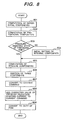
- Fig. 8 is a processing flowchart for realizing by software the pressure-decrease control function 110 and the pressure-current command conversion function 111 at the time of pressure decrease.
- Step 801 the differential components of the pressure deviation ⁇ P are computed.
- Step 802 the proportional components of the pressure deviation ⁇ P are computed.
- Step 803 the preceding control state is decided.
- the processing proceeds to Step 805.
- Step 805 the integral components are computed.
- the above-described three components are added. [ Equation 4 ]
- P RD K PD ⁇ ⁇ P + K ID ⁇ ⁇ ⁇ P d t + K DD ⁇ ⁇ P ⁇
- Step 807 a conversion is executed from the added control command P RD to the temporary current command I TMP .
- the premeasured current-pressure static characteristics at the time of pressure decrease is utilized.
- Step 809 the duty ratio of the PWM signal for the on-off operation of transistors is computed according to the measured value of the solenoid current and the current command I REF , then ending the routine.
- I REF I TMP + I LD
- Fig. 9 is a block diagram for adaptive cruise control with the distance control between a car and the one in front, in vehicle mounted with the invention.
- the vehicle is mounted with an engine 902, a transmission 903, a servo unit 101, a control device 904, and an adaptive cruise control device 901.
- the adaptive cruise control device 901 has at least the following five functions: a function to measure a distance from a vehicle running ahead and a relative vehicle speed, a function to set a target value of vehicle speed, a function to set a target value of engine torque for matching the target value of the vehicle speed with the measured value of the vehicle speed, a function to set a target value of a brake liquid pressure command for matching the target value of the vehicle speed with the measured value of the vehicle speed, and a function to set a target gear ratio of the transmission.
- the target value of engine torque is increased.
- the engine 902 is outputted the engine torque which has reached the target value of engine torque.
- the target value of the vehicle speed decreases according to the distance from the vehicle ahead and the relative vehicle speed the target value of the brake liquid pressure command is increased.
- the control device 904 of the servo unit 101 operates to realize the brake liquid pressure which has reached the target value of the pressure command, the vehicle speed decelerates, thereby the measured value of the vehicle speed matches with the target value.
- the control device 904 provided with the invention is able to smoothly increase and decrease the brake liquid pressure, therefore enabling the realization of smooth deceleration. It should be noticed that the vehicle can be decelerated to match the measured value with the target value of the vehicle speed, by decreasing the target value of engine torque, with the target value of the brake liquid pressure command left at zero, or by changing the gear ratio of the transmission.
- the constantly proper solenoid current can be supplied to the brake servo unit by updating the pressure-increase starting current learning value every time the pressure-increase is started except the first time after starting the device. This procedure is similarly applicable to the pressure decrease. It is, therefore, possible to smoothly control the brake liquid pressure albeit the servo unit working temperature changes.
Applications Claiming Priority (2)
| Application Number | Priority Date | Filing Date | Title |
|---|---|---|---|
| JP2001053424A JP3861609B2 (ja) | 2001-02-28 | 2001-02-28 | ブレーキ倍力装置の制御装置 |
| EP01122570A EP1238878B1 (de) | 2001-02-28 | 2001-09-25 | Bremsservosteuereinheit |
Related Parent Applications (1)
| Application Number | Title | Priority Date | Filing Date |
|---|---|---|---|
| EP01122570A Division EP1238878B1 (de) | 2001-02-28 | 2001-09-25 | Bremsservosteuereinheit |
Publications (4)
| Publication Number | Publication Date |
|---|---|
| EP1634786A2 true EP1634786A2 (de) | 2006-03-15 |
| EP1634786A3 EP1634786A3 (de) | 2006-03-22 |
| EP1634786B1 EP1634786B1 (de) | 2007-10-10 |
| EP1634786B8 EP1634786B8 (de) | 2008-02-13 |
Family
ID=18913890
Family Applications (2)
| Application Number | Title | Priority Date | Filing Date |
|---|---|---|---|
| EP05025476A Expired - Lifetime EP1634786B8 (de) | 2001-02-28 | 2001-09-25 | Bremsservosteuereinheit, -Verfahren, und -Fahrzeug |
| EP01122570A Expired - Lifetime EP1238878B1 (de) | 2001-02-28 | 2001-09-25 | Bremsservosteuereinheit |
Family Applications After (1)
| Application Number | Title | Priority Date | Filing Date |
|---|---|---|---|
| EP01122570A Expired - Lifetime EP1238878B1 (de) | 2001-02-28 | 2001-09-25 | Bremsservosteuereinheit |
Country Status (4)
| Country | Link |
|---|---|
| US (1) | US6637836B2 (de) |
| EP (2) | EP1634786B8 (de) |
| JP (1) | JP3861609B2 (de) |
| DE (2) | DE60130935T2 (de) |
Families Citing this family (5)
| Publication number | Priority date | Publication date | Assignee | Title |
|---|---|---|---|---|
| US20080270000A1 (en) * | 2004-11-10 | 2008-10-30 | Werner Bernzen | Preventive-Action Protection System in a Motor Vehicle |
| JP2008296740A (ja) | 2007-05-31 | 2008-12-11 | Hitachi Ltd | 車両挙動制御装置 |
| JP4815528B2 (ja) * | 2009-11-20 | 2011-11-16 | 日信工業株式会社 | 車両用ブレーキ液圧制御装置 |
| WO2013088823A1 (ja) * | 2011-12-12 | 2013-06-20 | 三菱電機株式会社 | 電磁ブレーキ状態診断装置およびその方法 |
| US9684310B2 (en) | 2015-07-17 | 2017-06-20 | Automatic Switch Company | Compensated performance of a solenoid valve based on environmental conditions and product life |
Citations (5)
| Publication number | Priority date | Publication date | Assignee | Title |
|---|---|---|---|---|
| DE19511845A1 (de) * | 1995-03-31 | 1996-10-02 | Teves Gmbh Alfred | Geregelter fremdansteuerbarer Bremskraftverstärker und Verfahren zu dessen Betrieb |
| DE19624376A1 (de) * | 1996-06-19 | 1998-01-02 | Teves Gmbh Alfred | Bremsanlage für Kraftfahrzeuge |
| DE19744053C1 (de) * | 1997-10-06 | 1998-10-22 | Lucas Ind Plc | Bremskraftverstärker |
| JP2001010481A (ja) * | 1999-04-30 | 2001-01-16 | Tokico Ltd | 倍力装置 |
| US6185498B1 (en) * | 1997-10-06 | 2001-02-06 | Lucas Industries Public Limited Company | Electronically controllable brake booster |
Family Cites Families (4)
| Publication number | Priority date | Publication date | Assignee | Title |
|---|---|---|---|---|
| DE19541101A1 (de) * | 1995-11-06 | 1997-05-07 | Teves Gmbh Alfred | Verfahren zum Betrieb eines pneumatischen Bremskraftverstärkers |
| DE19609192A1 (de) * | 1996-03-09 | 1997-09-11 | Teves Gmbh Alfred | Verfahren zum Betrieb eines pneumatischen Bremskraftverstärkers |
| DE19620540C2 (de) * | 1996-05-22 | 2001-06-13 | Lucas Automotive Gmbh | Elektronisch steuerbare Bremsanlage |
| JP3700523B2 (ja) * | 2000-02-25 | 2005-09-28 | 株式会社日立製作所 | 倍力装置の制御装置 |
-
2001
- 2001-02-28 JP JP2001053424A patent/JP3861609B2/ja not_active Expired - Fee Related
- 2001-09-25 DE DE60130935T patent/DE60130935T2/de not_active Expired - Lifetime
- 2001-09-25 EP EP05025476A patent/EP1634786B8/de not_active Expired - Lifetime
- 2001-09-25 DE DE60116824T patent/DE60116824T2/de not_active Expired - Lifetime
- 2001-09-25 EP EP01122570A patent/EP1238878B1/de not_active Expired - Lifetime
- 2001-09-25 US US09/961,439 patent/US6637836B2/en not_active Expired - Fee Related
Patent Citations (5)
| Publication number | Priority date | Publication date | Assignee | Title |
|---|---|---|---|---|
| DE19511845A1 (de) * | 1995-03-31 | 1996-10-02 | Teves Gmbh Alfred | Geregelter fremdansteuerbarer Bremskraftverstärker und Verfahren zu dessen Betrieb |
| DE19624376A1 (de) * | 1996-06-19 | 1998-01-02 | Teves Gmbh Alfred | Bremsanlage für Kraftfahrzeuge |
| DE19744053C1 (de) * | 1997-10-06 | 1998-10-22 | Lucas Ind Plc | Bremskraftverstärker |
| US6185498B1 (en) * | 1997-10-06 | 2001-02-06 | Lucas Industries Public Limited Company | Electronically controllable brake booster |
| JP2001010481A (ja) * | 1999-04-30 | 2001-01-16 | Tokico Ltd | 倍力装置 |
Non-Patent Citations (1)
| Title |
|---|
| PATENT ABSTRACTS OF JAPAN vol. 2000, no. 16, 8 May 2001 (2001-05-08) & JP 2001 010481 A (TOKICO LTD), 16 January 2001 (2001-01-16) * |
Also Published As
| Publication number | Publication date |
|---|---|
| US6637836B2 (en) | 2003-10-28 |
| DE60116824D1 (de) | 2006-04-13 |
| EP1634786B8 (de) | 2008-02-13 |
| EP1634786B1 (de) | 2007-10-10 |
| US20020117894A1 (en) | 2002-08-29 |
| JP3861609B2 (ja) | 2006-12-20 |
| EP1238878B1 (de) | 2006-01-25 |
| EP1238878A2 (de) | 2002-09-11 |
| EP1634786A3 (de) | 2006-03-22 |
| EP1238878A3 (de) | 2004-03-10 |
| JP2002255024A (ja) | 2002-09-11 |
| DE60130935D1 (de) | 2007-11-22 |
| DE60116824T2 (de) | 2006-09-14 |
| DE60130935T2 (de) | 2008-06-12 |
Similar Documents
| Publication | Publication Date | Title |
|---|---|---|
| AU622969B2 (en) | Improvements in fluid-pressure operated boosters for vehicle braking systems | |
| EP2014526B1 (de) | Steuersystem für Kraftfahrzeug | |
| US10919512B2 (en) | Method for detecting a leakage during operation of a braking system for a vehicle and braking system for a vehicle | |
| US8781701B2 (en) | Vehicle regeneration cooperative braking system | |
| JP5295750B2 (ja) | ブレーキ装置の制御装置 | |
| US5433514A (en) | Pressure control actuator for a brake control system | |
| US5372409A (en) | Fluid-pressure operated boosters for vehicle braking systems | |
| US10703348B2 (en) | Hydraulic pressure control device | |
| CN108137016B (zh) | 液压压力控制装置 | |
| EP1634786B1 (de) | Bremsservosteuereinheit, -Verfahren, und -Fahrzeug | |
| US8348351B2 (en) | Brake control device | |
| US8718895B2 (en) | Method for determining the wheel pressure in an electronically actuatable motor vehicle brake control system | |
| US11148653B2 (en) | Method for avoiding excess pressures in a pressure medium circuit of an electronically slip-controllable braking system in the event of a decline of an intrinsic elasticity of the braking system and electronically slip-controllable braking system | |
| US8915555B2 (en) | Brake control device for vehicle | |
| US11958453B2 (en) | Method for operating a brake system, and brake system | |
| US11279332B2 (en) | Braking force control apparatus for vehicle | |
| EP1925514B1 (de) | Bewegungssteuervorrichtung und bewegungssteuerverfahren | |
| US11964643B2 (en) | Vehicle braking device | |
| US20200047728A1 (en) | Method for controlling an electronically slip-controllable power braking system and electronically slip-controllable power braking system | |
| US20040232764A1 (en) | Method for improving the regulation behavior of a slip control system | |
| JP2006151394A (ja) | ブレーキ倍力装置の制御装置 | |
| RU2041090C1 (ru) | Тормозная система транспортного средства и гидравлическая тормозная система | |
| KR20160005381A (ko) | 차량 유압 제동장치 및 그 제어방법 | |
| JP4779231B2 (ja) | 車両の制動制御装置 | |
| JPH04507074A (ja) | 車両の制御システム |
Legal Events
| Date | Code | Title | Description |
|---|---|---|---|
| PUAI | Public reference made under article 153(3) epc to a published international application that has entered the european phase |
Free format text: ORIGINAL CODE: 0009012 |
|
| PUAL | Search report despatched |
Free format text: ORIGINAL CODE: 0009013 |
|
| AC | Divisional application: reference to earlier application |
Ref document number: 1238878 Country of ref document: EP Kind code of ref document: P |
|
| AK | Designated contracting states |
Kind code of ref document: A2 Designated state(s): DE FR GB |
|
| AK | Designated contracting states |
Kind code of ref document: A3 Designated state(s): DE FR GB |
|
| 17P | Request for examination filed |
Effective date: 20060331 |
|
| AKX | Designation fees paid |
Designated state(s): DE FR GB |
|
| GRAP | Despatch of communication of intention to grant a patent |
Free format text: ORIGINAL CODE: EPIDOSNIGR1 |
|
| RIN1 | Information on inventor provided before grant (corrected) |
Inventor name: YOKOHAMA, ATSUSHIC Inventor name: KURAGAKI, SATORU,C Inventor name: YOSHIKAWA, TOKUJIC Inventor name: MANAKA, TOSHIO,C |
|
| RIN1 | Information on inventor provided before grant (corrected) |
Inventor name: YOSHIKAWA, TOKUJIC/O HITACHI LTD.,INTEL. PROPERTY Inventor name: MANAKA, TOSHIO,C/O HITACHI LTD.,INTEL. PROPERTY GP Inventor name: YOKOHAMA, ATSUSHIC/O HITACHI LTD.,INTEL. PROPERTY Inventor name: KURAGAKI, SATORU,C/O HITACHI LTD.,INTEL. PROPERTY |
|
| GRAS | Grant fee paid |
Free format text: ORIGINAL CODE: EPIDOSNIGR3 |
|
| GRAA | (expected) grant |
Free format text: ORIGINAL CODE: 0009210 |
|
| AC | Divisional application: reference to earlier application |
Ref document number: 1238878 Country of ref document: EP Kind code of ref document: P |
|
| AK | Designated contracting states |
Kind code of ref document: B1 Designated state(s): DE FR GB |
|
| REG | Reference to a national code |
Ref country code: GB Ref legal event code: FG4D |
|
| RIN1 | Information on inventor provided before grant (corrected) |
Inventor name: MANAKA, TOSHIO,C/O HITACHI LTD.,INTEL. PROPERTY GP Inventor name: YOSHIKAWA, TOKUJIC/O HITACHI LTD.,INTEL. PROPERTY Inventor name: YOKOHAMA, ATSUSHIC/O HITACHI LTD.,INTEL. PROPERTY Inventor name: KURAGAKI, SATORU,C/O HITACHI LTD.,INTEL. PROPERTY |
|
| REF | Corresponds to: |
Ref document number: 60130935 Country of ref document: DE Date of ref document: 20071122 Kind code of ref document: P |
|
| RIN2 | Information on inventor provided after grant (corrected) |
Inventor name: MANAKA, TOSHIO,C/O HITACHI LTD.,INTEL. PROPERTY GP Inventor name: KURAGAKI, SATORU,C/O HITACHI LTD.,INTEL. PROPERTY Inventor name: YOSHIKAWA, TOKUJIC/O HITACHI LTD.,INTEL. PROPERTY Inventor name: YOKOYAMA, ATSUSHIC/O HITACHI LTD.,INTEL. PROPERTY |
|
| ET | Fr: translation filed | ||
| PLBE | No opposition filed within time limit |
Free format text: ORIGINAL CODE: 0009261 |
|
| STAA | Information on the status of an ep patent application or granted ep patent |
Free format text: STATUS: NO OPPOSITION FILED WITHIN TIME LIMIT |
|
| 26N | No opposition filed |
Effective date: 20080711 |
|
| PGFP | Annual fee paid to national office [announced via postgrant information from national office to epo] |
Ref country code: GB Payment date: 20130925 Year of fee payment: 13 Ref country code: FR Payment date: 20130910 Year of fee payment: 13 |
|
| PGFP | Annual fee paid to national office [announced via postgrant information from national office to epo] |
Ref country code: DE Payment date: 20140917 Year of fee payment: 14 |
|
| GBPC | Gb: european patent ceased through non-payment of renewal fee |
Effective date: 20140925 |
|
| REG | Reference to a national code |
Ref country code: FR Ref legal event code: ST Effective date: 20150529 |
|
| PG25 | Lapsed in a contracting state [announced via postgrant information from national office to epo] |
Ref country code: GB Free format text: LAPSE BECAUSE OF NON-PAYMENT OF DUE FEES Effective date: 20140925 |
|
| PG25 | Lapsed in a contracting state [announced via postgrant information from national office to epo] |
Ref country code: FR Free format text: LAPSE BECAUSE OF NON-PAYMENT OF DUE FEES Effective date: 20140930 |
|
| REG | Reference to a national code |
Ref country code: DE Ref legal event code: R119 Ref document number: 60130935 Country of ref document: DE |
|
| PG25 | Lapsed in a contracting state [announced via postgrant information from national office to epo] |
Ref country code: DE Free format text: LAPSE BECAUSE OF NON-PAYMENT OF DUE FEES Effective date: 20160401 |