EP1634709A1 - méthode d'impression à dissimulation d'éléments d'impression défectueux - Google Patents
méthode d'impression à dissimulation d'éléments d'impression défectueux Download PDFInfo
- Publication number
- EP1634709A1 EP1634709A1 EP04104428A EP04104428A EP1634709A1 EP 1634709 A1 EP1634709 A1 EP 1634709A1 EP 04104428 A EP04104428 A EP 04104428A EP 04104428 A EP04104428 A EP 04104428A EP 1634709 A1 EP1634709 A1 EP 1634709A1
- Authority
- EP
- European Patent Office
- Prior art keywords
- pixels
- pixel
- gamma correction
- image
- printed
- Prior art date
- Legal status (The legal status is an assumption and is not a legal conclusion. Google has not performed a legal analysis and makes no representation as to the accuracy of the status listed.)
- Withdrawn
Links
Images


Classifications
-
- B—PERFORMING OPERATIONS; TRANSPORTING
- B41—PRINTING; LINING MACHINES; TYPEWRITERS; STAMPS
- B41J—TYPEWRITERS; SELECTIVE PRINTING MECHANISMS, i.e. MECHANISMS PRINTING OTHERWISE THAN FROM A FORME; CORRECTION OF TYPOGRAPHICAL ERRORS
- B41J2/00—Typewriters or selective printing mechanisms characterised by the printing or marking process for which they are designed
- B41J2/005—Typewriters or selective printing mechanisms characterised by the printing or marking process for which they are designed characterised by bringing liquid or particles selectively into contact with a printing material
- B41J2/01—Ink jet
- B41J2/21—Ink jet for multi-colour printing
- B41J2/2132—Print quality control characterised by dot disposition, e.g. for reducing white stripes or banding
- B41J2/2139—Compensation for malfunctioning nozzles creating dot place or dot size errors
Definitions
- the invention relates to a printing method for a printer having a printhead with a plurality of print elements and capable of printing a binary pixel image, the method comprising the steps of: locating defective print elements, determining a camouflage area in the vicinity of pixels that would have to be printed with the defective print elements, and camouflaging defective print elements by modifying image information in said camouflage area.
- the invention further relates to a printer and to a computer program implementing this method.
- the invention is applicable, for example, to an ink jet printer the printhead of which comprises a plurality of nozzles as print elements.
- the nozzles are arranged in a line that extends in parallel with the direction (subscanning direction) in which a recording medium, e.g. paper, is transported through the printer, and the printhead scans the paper in a direction (main scanning direction) perpendicular to the subscanning direction.
- a recording medium e.g. paper
- main scanning direction perpendicular to the subscanning direction.
- a single-pass mode is each line printed by only one printing element during a single pass of the printhead.
- a printer may also be operated in a multi-pass mode, wherein each line is printed by at least two printing elements. In this case, it is sometimes possible that a defective nozzle is backed-up by a non-defective nozzle, though on the cost of productivity.
- US-A-6 215 557 discloses a method of the type indicated above, wherein, when a nozzle is defective, the print data are altered so as to bypass the faulty nozzle. This means that a pixel that would have but cannot be printed with the defective nozzle is substituted by printing an extra pixel in one of the neighbouring lines that are printed with non-defective nozzles, so that the average optical density of the image area is conserved and the defect resulting from the nozzle failure is camouflaged and becomes almost imperceptible.
- This method involves a specific algorithm that operates on a bitmap, which represents the print data, and shifts each pixel that cannot be printed to a neighbouring pixel position. However, if this neighbouring pixel position happens to be occupied by a pixel already printed, anyway, pursuant to the original print data, then the extra pixel cannot be printed, and a loss of image information will nevertheless occur.
- the camouflaging step comprises the steps of modifying a gamma correction function to a modified gamma correction function and using said modified gamma correction function in said camouflage area.
- gamma curve As is well known in the art, the relationship between grey values of pixels to be printed, as encoded in the print data, and the optical density with which the pixel is actually reproduced on the recording medium is described by a so-called gamma curve. This curve is determined by the physical properties of the print process and is in most cases non-linear, so that a linearisation or gamma correction process is required for making sure that slight differences in the grey values in the original image are reproduced equally well over the whole scale of grey levels. Thus, a gamma correction step is typically included in the data processing that is involved in a printing method.
- the fact that a print element of the printer is defective is considered as a physical factor that changes the effective gamma curve of the printer for those areas of the printed image that are affected by the defect, e.g. by a nozzle failure in case of an ink jet printer.
- the procedure for camouflaging the effect of the nozzle failure can be implemented very easily by appropriately adapting the gamma correction for the pertinent image area.
- the well-known mechanisms that are normally used for correcting the non-linearities of the gamma curve will function to achieve an optical density of the printed image that corresponds to the grey levels of the original image as far as possible, in spite of the nozzle failure.
- the invention permits to implement the camouflage step in a very rational way and with only a minimum requirement for data processing time and capacity.
- the gamma correction is performed on the level of the grey value image, i.e. an electronic representation of the image to be printed in the form of a multi-level pixel matrix, where the grey level of each matrix element or pixel is represented by a data word of several bits, e.g. 8 bits, so that the grey levels may range from 0 (white) to 255 (black).
- one of a plurality of well-known algorithms such as error diffusion or dithering is used for converting the multi-level pixel matrix into a binary pixel image or bitmap such that, although the pixels of the bitmap are either black or white, the distribution of black and white pixels, on the average, still reflects the grey levels of the multi-level pixel matrix.
- bitmap does not mean that a bitmap must actually be stored physically in a storage medium, but only means that the print data are provided in binary form, so that each pixel is represented by a single bit. Thus, the "bitmap” may well be generated “on the fly” during the print process.
- the camouflage process provides a high degree of flexibility because it is based on the multi-level pixel matrix where the grey levels can be finely adjusted so as to achieve optimal results.
- Another advantage is that the method can be carried out at a comparatively early stage in the processing sequence, so that the method can also be adapted, for example, to printer hardware which has no sufficient processing capability for carrying out corrections on bitmap level. It is even possible that the method according to the invention is executed in a host computer from which the print data are sent to the printer, provided that the information on the defective nozzles (and the normal gamma curve) of the printer is made available at the host computer. Then, if the printer forms part of a multi-user network, the data processing necessary for carrying out the invention may be distributed over a plurality of computers in the network.
- the invention will also increase the likelihood that the black pixels that cannot be printed are actually shifted to empty pixel positions in the neighbourhood rather than being lost.
- the invention is particularly useful when the print data that are supplied to the printer are in the multi-level format. However, if these data are in the binary format already, it is a simple matter to reconvert these data into multi-level data, with or without averaging over clusters of adjacent pixels, and then to employ the method as described above.
- the camouflage area where the modified gamma curve applies will be formed by one or more pixel lines adjacent to the line that is affected by the nozzle failure.
- the camouflage area may then comprise the two direct neighbours of the line that cannot be printed.
- the invention is also applicable in multi-pass printing. Then, a nozzle failure will generally not have the effect that a complete line is missing in the printed image, but that, for example in the case of two-pass printing, typically only half the pixels in the line will be missing.
- the camouflage area may consist of the remaining, printable pixels in the line in which half of the pixels are missing.
- the camouflage area may also be extended to the adjacent lines.
- the input to the gamma correction process utilising the modified gamma curve may consist only of the lines or pixels that can be printed, and the image information of the non-printable lines or pixels may be ignored.
- an ink jet printer comprises a platen 10 which serves for transporting a recording paper 12 in a subscanning direction (arrow A) past a printhead unit 14.
- the printhead unit 14 is mounted on a carriage 16 that is guided on guide rails 18 and is movable back and forth in a main scanning direction (arrow B) relative to the recording paper 12.
- the printhead unit 14 comprises four printheads 20, one for each of the basic colours cyan, magenta, yellow and black.
- Each printhead has a linear array of nozzles 22 extending in the subscanning direction.
- the nozzles 22 of the printheads 20 can be energised individually to eject ink droplets onto the recording paper 12, thereby to print a pixel on the paper.
- a swath of an image can be printed.
- the number of pixel lines of the swath corresponds to the number of nozzles 22 of each printhead.
- the printheads 20 are controlled by a processing unit 24 which processes the print data in a manner that will be described in detail hereinbelow. The discussion will be focused on printing in black colour, but is equivalently valid for printing in the other colours.
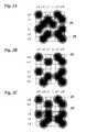
- Figure 2A shows an array of 6x6 pixels 26, which represents a portion of an image to be printed.
- the pixels 26 are arranged in lines i-3, i-2, i-1, i, i+1, i+2 and columns j-3, j-2, j-1, j. j+1 and j+2.
- Black pixels are indicated by dots 28 as printed with the ink jet printer shown in figure 1. Since the ink droplet forming a dot 28 tends to spread on the recording medium (paper), the optical density of the dot decreases gradually from the center toward the periphery, and the lighter peripheral portions of the dot extend beyond the area of the pixel, so that neighbouring dots overlap.
- the image that has been shown in largely magnified scale in figure 2A would give the impression of a uniform grey area.
- Figure 2B shows the same image in the case that the nozzle needed for printing the line i is defective, so that the dots at the pixel positions (i, j-2) and (i, j) are missing. This would give rise to a perceptible brighter gap in the printed image at the position of the line i.
- the processing unit 24 shown in figure 1 performs a camouflage step which, in the given example, leads to the insertion of an additional dot 30 at the pixel position (i-1, j-1), i.e. in the pixel line i-1 directly adjacent to the defective line i.
- the image shown in figure 2C resembles the ideal image shown in figure 2A.
- the print data are supplied to the printer in a multi-level format, in which the grey value of each pixel is indicated by an 8-bit word, i.e. by an integral number between 0 and 255.
- the number 0 represents a white pixel and the number 255 a black pixel with maximum optical density.
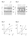
- the print data are thus represented by a multi-level pixel matrix 32 as is schematically shown in figure 3.
- each pixel line of this pixel matrix will be printed by only one of the nozzles 22 of the printhead.
- the printer may be equipped with a detection system which automatically detects and locates defective nozzles.
- the location of a defective nozzle may also be input by the user.
- the pixels in the line i are non-printable pixels 34. These pixels have been left white in figure 3.
- Printable pixels 36 are indicated by a light hatching.
- one or more adjacent lines i-1 and i+1 are defined as a camouflage area 38 which will be used for camouflaging the defect in line i.
- the printable pixels 38 are indicated by a frequent hatching and are part of the camouflage area 38.
- figure 4 illustrates the case of a two-pass print mode, where two nozzles of the printhead are involved in printing the pixels of the same line.
- half of the pixels will be a non-printable pixel 34, such as the pixels in columns j-3, j-1 and j+1 in figure 4.
- the camouflage area 38 may then be formed by the remaining printable pixels in line i (i. e. the pixels in columns j-2, j and j+2).
- the camouflage area 38 may also include the pixels in the two adjacent lines i-1 and i+1, as is shown in figure 4.
- Figure 5 shows an example of a gamma curve 40 which specifies the relation between a grey value gc of the pixels as supplied to the halftoning process and the optical density OD with which the pixels will actually be printed on the recording medium.
- the curve 40 is the normal gamma curve of the printer, i.e. it pertains to the case that there is no nozzle defect.
- the curve 42 represents a gamma correction function that is used for correcting the gamma curve 40 shown in figure 5, as is well known in the art.
- This correction function defines a relation between the original grey value g and the corrected grey value gc.
- the gamma correction function 42 is obtained by inverting the function represented by the gamma curve 40 such that a visually pleasing transfer curve is obtained.
- the conventional gamma correction process which is employed here for the printable pixels 36, the original grey value g of each pixel is subjected to the gamma correction function 42, and the result is a corrected grey value gc.
- a gamma-corrected pixel matrix is obtained in which each matrix element contains the corrected grey value gc of the corresponding pixel.
- This corrected pixel matrix is then subjected to a conventional halftoning process such as dithering or error diffusion, so that the corrected pixel matrix is converted into a bitmap in which each pixel as a binary value, either 0 for a white pixel or 1 for a black pixel.
- the halftoning process and printing process results in a relation between the corrected grey value gc and the optical density OD, which relation is represented by the gamma curve 40. Since the correctional function 42 is essentially inverse to the gamma curve 40, one finally obtains a practically linear relation between the original grey values g and the corresponding optical densities OD.
- curve 44 depends on the spatial size with which the optical densities OD are sampled.
- a sampling and camouflage region of 3 lines the line i of the defective nozzle, and the lines i+1 and i-1 directly adjacent to it.
- the inverse of this factor can be used in a correction routine.
- the camouflage region is 5 lines wide this factor is 4/5.
- a modified gamma correction curve 46 is used for gamma correction in the camouflage area 38. If, for example, a pixel in the original print data has the grey value g1, the modified gamma correction function 46 will yield the (modified) corrected grey value gc1. Now, the conventional halftoning process is performed without any further modifications for the pixels in the camouflage area 38. Since the (modified) corrected grey value gc1 is larger than the (not modified) corrected grey value gc1 (not depicted), this has the effect that additional black pixels are added in the camouflage area 38.
- the effect of the print process with the defective nozzle in line i is governed by the modified gamma curve 44.
- This curve links the corrected grey value gc1 to an optical density OD1 which is proportional to the original grey value g1 of the pixel.
- the nozzle defects in line i is camouflaged in the manner as shown in figure 2C.
- the grey value g1 for any pixel can only be in the range between 0 and 255. It should be noted however, that the corrected grey value gc1 may become larger than 255. When halftoning is achieved by error diffusion, for example, such larger values beyond 255 may well be processed and lead to the insertion of additional black pixels.
- camouflage process described above is particularly efficient for images which mainly contain small or medium grey levels. In case of very dark images and, in the extreme, in the case of solid black areas, it is increasingly difficult or even impossible to add more black pixels in the camouflage area. Nevertheless, the camouflage process may be useful even for dark or black images, depending upon the design of the printer. Some known printers are capable of printing a plainly black area even when the percentage of black pixels in the bitmap is somewhat smaller than 100%. In this case, the modified gamma correction in the camouflage area 38 may lead to an over-saturated bitmap which would still mask the nozzle defect to some extent.
- the appropriate form of the modified gamma correction curve 46 will generally depend on several physical parameters such as the size of ink droplets produced by the printhead, the resolution of the printer, the spreading of the ink on the recording paper and the like. Obviously, the correction function will also depend on the print mode and on the definition of the camouflage area. For example, in figure 3, where the single-pass mode is employed and the camouflage area 38 is formed by the two lines directly adjacent to the defective line. For this example, in a simplified approach, a suitable modified gamma correction function may also be obtained by multiplying the regular gamma correction function 42 with a predetermined factor of 3/2. In case of one line directly adjacent to the defective line a suitable modified correction function is obtained by for example multiplying the regular gamma correction function 42 with a predetermined factor 2.
- the factor for modifying the gamma correction function would be 6/5, when the adjacent lines i+1, i-1 and half of the pixels of line i are included in the camouflage area 38.
- the factor would be 2.
- the correction curve 46 may be determined on the basis of a direct measurement of the corresponding gamma curve 44 by disabling one of the nozzles of the printer and measuring the optical density of the printed image for different grey levels of the original image.
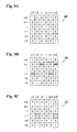
- step S100 the multi-level pixel matrix 32 is established by reading the grey values g.
- the pixel lines that are affected by nozzle failures of the printhead are identified in step S101.
- step S102 the camouflage area 38 surrounding these pixel lines is determined.
- step S103 consists of a conventional gamma correction for all the pixels of the pixel matrix on the basis of the regular gamma correction function 42.
- the corrected grey values gc corresponding to the original grey value g of each pixel are calculated or looked-up in a table.
- step S104 For all the pixels in the camouflage area 38 the corrected grey values gc are modified in step S104 by multiplying the corrected grey values gc with a predetermined factor, whereas the values gc for the printable pixels 36 are left as they are.
- This step results for all the pixels in the camouflage area 38 to a shift from the gamma correction function 42 to the modified gamma correction function 46.
- Step S105 is a conventional halftone step, e.g. dithering or error diffusion, and leads to the insertion of black pixels in the camouflage area 38.
- the resulting bitmap is then printed in step S106.
- the step S100 may be performed after the step S101 or even after the step S102. Then, the grey values for the non-printable pixels 34 need not be read, because they are not utilised in the further process.
- step 103 and 104 for the camouflage area. This effectively results in an identical data flow for the whole image, in which only the function gc(g) is different in the camouflage area than outside the camouflage area.
- step S104 in figure 7 An alternative for step S104 in figure 7 is that the modified gamma correction function is determined by a measuring method.
- the modified gamma function can be determined the same way as the gamma function, except the method applies to print optical density areas with a simulated defective print element comprising the following steps:
- Figure 8 illustrates another embodiment which is adapted to the case that the print data are presented already in the format of a bitonal bitmap, i.e. a matrix of only black and white pixels.
- the bitmap is read in step S200.
- the steps S201 and S202 correspond to the steps S101 and S102 discussed above. It is assumed here that the bitmap data read in step S200 have already been subjected to a regular gamma correction in the process in which the bitmap has been established. Thus, a regular gamma correction step corresponding to the step S103 in figure 7 is omitted in the embodiment of figure 8.
- step S204 the bitmap is reconverted into a multi-level pixel matrix.
- n is an integral number that has been appropriately selected to represent the shift from the regular gamma correction curve 42 to the modified curve 46.
- the number n may be constant or may be varied in accordance with the average grey level in a pixel cluster surrounding the pertinent pixel in the camouflage area.
- figure 8 has been exemplified for the single-pass mode, but it goes without saying that this method is also applicable to a multi-pass mode, as has been described in conjunction with figure 4.
- Figure 9A shows an example of the bitmap read in step S200. Again, it is assumed that the nozzle that is responsible for printing the pixels in line i in the single-pass mode is defective.
- Figure 9C shows the final bitmap or binary pixel image 52 resulting from the error diffusion step S205.
- error diffusion is performed by carrying the error from one pixel only to the next pixel in the same line.
- the corrected grey value gc of the black pixel (i+1, j-1) is 383, which is larger than the threshold value of 255. This gives a black pixel "1" in figure 9C, and the threshold value of 255 is subtracted from 383.
- the rest (i. e. 128) is carried to the next pixel (i+1, j). Since this rest is smaller than the threshold value, this pixel is left white ("0"), and the rest is carried-on to the next pixel and then to the pixel (i+1, j+2).
- the accumulated error is 511, which is larger than 255, so that this pixel is made black.
- the rest of 256 is carried to the next pixel which in this case is the first pixel in the next line of the camouflage area, i.e.. the pixel (i-1, j-3). This pixel is made black, and the rest (384) is carried to the next pixel (i-1, j-2) which gives an additional black pixel in this position. The rest is carried through the subsequent pixels and finally results in another additional black pixel in the position (i-1, j+2).
- two new pixels are added in line i-1 in order to camouflage the defect in line i.
Landscapes
- Engineering & Computer Science (AREA)
- Quality & Reliability (AREA)
- Ink Jet (AREA)
Priority Applications (1)
| Application Number | Priority Date | Filing Date | Title |
|---|---|---|---|
| EP04104428A EP1634709A1 (fr) | 2004-09-14 | 2004-09-14 | méthode d'impression à dissimulation d'éléments d'impression défectueux |
Applications Claiming Priority (1)
| Application Number | Priority Date | Filing Date | Title |
|---|---|---|---|
| EP04104428A EP1634709A1 (fr) | 2004-09-14 | 2004-09-14 | méthode d'impression à dissimulation d'éléments d'impression défectueux |
Publications (1)
| Publication Number | Publication Date |
|---|---|
| EP1634709A1 true EP1634709A1 (fr) | 2006-03-15 |
Family
ID=34929568
Family Applications (1)
| Application Number | Title | Priority Date | Filing Date |
|---|---|---|---|
| EP04104428A Withdrawn EP1634709A1 (fr) | 2004-09-14 | 2004-09-14 | méthode d'impression à dissimulation d'éléments d'impression défectueux |
Country Status (1)
| Country | Link |
|---|---|
| EP (1) | EP1634709A1 (fr) |
Cited By (7)
| Publication number | Priority date | Publication date | Assignee | Title |
|---|---|---|---|---|
| JP2015145085A (ja) * | 2014-02-03 | 2015-08-13 | セイコーエプソン株式会社 | 画像形成装置、及び、ドットパターン決定方法 |
| JP2015150751A (ja) * | 2014-02-13 | 2015-08-24 | セイコーエプソン株式会社 | 画像形成装置、及び、ドットパターン決定方法 |
| JP2016182775A (ja) * | 2015-03-26 | 2016-10-20 | 株式会社Screenホールディングス | 画像記録装置、印字データ補正装置および印字データ補正方法 |
| JP2016193534A (ja) * | 2015-03-31 | 2016-11-17 | ブラザー工業株式会社 | インクジェットプリンタ、及び印刷方法 |
| JP2016215395A (ja) * | 2015-05-14 | 2016-12-22 | 株式会社リコー | 液体を吐出する装置、画像データを処理する方法、プログラム |
| JP2017136731A (ja) * | 2016-02-02 | 2017-08-10 | 株式会社リコー | 画像処理方法、画像処理装置、及びプログラム |
| WO2021070662A1 (fr) * | 2019-10-10 | 2021-04-15 | 株式会社ミマキエンジニアリング | Dispositif d'impression et procédé de correction |
Citations (2)
| Publication number | Priority date | Publication date | Assignee | Title |
|---|---|---|---|---|
| US6215557B1 (en) | 1999-07-01 | 2001-04-10 | Lexmark International, Inc. | Entry of missing nozzle information in an ink jet printer |
| EP1151867A2 (fr) * | 2000-05-01 | 2001-11-07 | Canon Kabushiki Kaisha | Appareil et méthode d'enregistrement |
-
2004
- 2004-09-14 EP EP04104428A patent/EP1634709A1/fr not_active Withdrawn
Patent Citations (2)
| Publication number | Priority date | Publication date | Assignee | Title |
|---|---|---|---|---|
| US6215557B1 (en) | 1999-07-01 | 2001-04-10 | Lexmark International, Inc. | Entry of missing nozzle information in an ink jet printer |
| EP1151867A2 (fr) * | 2000-05-01 | 2001-11-07 | Canon Kabushiki Kaisha | Appareil et méthode d'enregistrement |
Cited By (8)
| Publication number | Priority date | Publication date | Assignee | Title |
|---|---|---|---|---|
| JP2015145085A (ja) * | 2014-02-03 | 2015-08-13 | セイコーエプソン株式会社 | 画像形成装置、及び、ドットパターン決定方法 |
| JP2015150751A (ja) * | 2014-02-13 | 2015-08-24 | セイコーエプソン株式会社 | 画像形成装置、及び、ドットパターン決定方法 |
| JP2016182775A (ja) * | 2015-03-26 | 2016-10-20 | 株式会社Screenホールディングス | 画像記録装置、印字データ補正装置および印字データ補正方法 |
| JP2016193534A (ja) * | 2015-03-31 | 2016-11-17 | ブラザー工業株式会社 | インクジェットプリンタ、及び印刷方法 |
| JP2016215395A (ja) * | 2015-05-14 | 2016-12-22 | 株式会社リコー | 液体を吐出する装置、画像データを処理する方法、プログラム |
| JP2017136731A (ja) * | 2016-02-02 | 2017-08-10 | 株式会社リコー | 画像処理方法、画像処理装置、及びプログラム |
| WO2021070662A1 (fr) * | 2019-10-10 | 2021-04-15 | 株式会社ミマキエンジニアリング | Dispositif d'impression et procédé de correction |
| JP2021062491A (ja) * | 2019-10-10 | 2021-04-22 | 株式会社ミマキエンジニアリング | 印刷装置及び補正方法 |
Similar Documents
| Publication | Publication Date | Title |
|---|---|---|
| EP1529644B1 (fr) | Procédé pour camoufler des éléments d'impression fautifs dans une imprimante | |
| JP4954494B2 (ja) | 欠陥印刷素子のカムフラージを用いた印刷方法 | |
| JP6016588B2 (ja) | 画像処理装置、記録装置および画像処理方法 | |
| JP2002029074A (ja) | 画像処理方法および画像記録装置 | |
| US7190485B2 (en) | Method for multilevel printing of digital images using reduced colorant amounts | |
| US7798589B2 (en) | Image forming apparatus, image processing apparatus, and control method therefor | |
| JP6021600B2 (ja) | 画像処理装置および画像処理方法 | |
| EP2842750B1 (fr) | Procédé de traitement d'image, dispositif de traitement d'image, dispositif de formation d'image et dispositif d'impression d'image à jet d'encre | |
| US7265770B2 (en) | Method of camouflaging defective print elements in a printer | |
| US8896883B2 (en) | Image processing apparatus, printing apparatus, and image processing method | |
| EP1648154A2 (fr) | Dispositif et procédé de traitement d'images en demi-teintes, dispositif d'impression | |
| JP2004284279A (ja) | 画像処理装置、画像処理方法及び画像処理プログラム | |
| JP6012425B2 (ja) | 画像処理装置および画像処理方法 | |
| EP1634709A1 (fr) | méthode d'impression à dissimulation d'éléments d'impression défectueux | |
| US7290846B2 (en) | Printing apparatus, printing apparatus control program, printing apparatus control method, printing data creating apparatus, printing data creating program and printing data creating method | |
| JP2005305785A (ja) | 画像形成装置、画像形成方法及び画像形成プログラム | |
| JP7446792B2 (ja) | 画像処理装置、画像処理方法及びプログラム | |
| EP1593516B1 (fr) | Méthode d'impression avec camouflage des élements d'impression défectueux | |
| JP2006247918A (ja) | 印刷装置、印刷プログラム、印刷方法および画像処理装置、画像処理プログラム、画像処理方法、並びに前記プログラムを記録した記録媒体 | |
| EP1536371B1 (fr) | Procédé de camoufler les défauts des éléments d'impression dans une imprimante | |
| JP4194326B2 (ja) | 補正テーブルの作成方法およびその作成装置 | |
| JP4065510B2 (ja) | 補正テーブルの作成方法およびその作成装置の制御方法 | |
| US20040100646A1 (en) | Spacing out output of pixels for other color components upon output of pixel for color component of an image pixel | |
| US11956403B1 (en) | Edge enhancement with compensation mechanism | |
| JP5288918B2 (ja) | 画像形成装置及びその制御方法、プログラム |
Legal Events
| Date | Code | Title | Description |
|---|---|---|---|
| PUAI | Public reference made under article 153(3) epc to a published international application that has entered the european phase |
Free format text: ORIGINAL CODE: 0009012 |
|
| AK | Designated contracting states |
Kind code of ref document: A1 Designated state(s): AT BE BG CH CY CZ DE DK EE ES FI FR GB GR HU IE IT LI LU MC NL PL PT RO SE SI SK TR |
|
| AX | Request for extension of the european patent |
Extension state: AL HR LT LV MK |
|
| STAA | Information on the status of an ep patent application or granted ep patent |
Free format text: STATUS: THE APPLICATION HAS BEEN WITHDRAWN |
|
| 18W | Application withdrawn |
Effective date: 20060719 |