EP1634674B1 - Schutzvorrichtung einer Laserbearbeitungseinheit - Google Patents
Schutzvorrichtung einer Laserbearbeitungseinheit Download PDFInfo
- Publication number
- EP1634674B1 EP1634674B1 EP04021785A EP04021785A EP1634674B1 EP 1634674 B1 EP1634674 B1 EP 1634674B1 EP 04021785 A EP04021785 A EP 04021785A EP 04021785 A EP04021785 A EP 04021785A EP 1634674 B1 EP1634674 B1 EP 1634674B1
- Authority
- EP
- European Patent Office
- Prior art keywords
- laser processing
- protection device
- basic frame
- dividing wall
- partition
- Prior art date
- Legal status (The legal status is an assumption and is not a legal conclusion. Google has not performed a legal analysis and makes no representation as to the accuracy of the status listed.)
- Expired - Lifetime
Links
Images


Classifications
-
- B—PERFORMING OPERATIONS; TRANSPORTING
- B23—MACHINE TOOLS; METAL-WORKING NOT OTHERWISE PROVIDED FOR
- B23K—SOLDERING OR UNSOLDERING; WELDING; CLADDING OR PLATING BY SOLDERING OR WELDING; CUTTING BY APPLYING HEAT LOCALLY, e.g. FLAME CUTTING; WORKING BY LASER BEAM
- B23K37/00—Auxiliary devices or processes, not specially adapted for a procedure covered by only one of the other main groups of this subclass
- B23K37/006—Safety devices for welding or cutting
-
- B—PERFORMING OPERATIONS; TRANSPORTING
- B23—MACHINE TOOLS; METAL-WORKING NOT OTHERWISE PROVIDED FOR
- B23K—SOLDERING OR UNSOLDERING; WELDING; CLADDING OR PLATING BY SOLDERING OR WELDING; CUTTING BY APPLYING HEAT LOCALLY, e.g. FLAME CUTTING; WORKING BY LASER BEAM
- B23K26/00—Working by laser beam, e.g. welding, cutting or boring
- B23K26/70—Auxiliary operations or equipment
- B23K26/702—Auxiliary equipment
- B23K26/706—Protective screens
Definitions
- the invention relates to a laser processing protection device.
- sliding doors are used as a protective device and / or subdivision of self-sufficient work areas.
- the doors are slidably mounted so that a boom and / or a laser processing head can change the working area. In one work area find preparatory measures and in the other work area laser machining takes place at the same time.
- a laser processing protection device It is a base frame provided with a U-shaped guide of the partition wall, wherein the partition through the base frame transverse to the longitudinal direction of the base frame and at the two Long sides of the base frame can be moved out of the base frame out. If in each case one half of the dividing wall can be moved out of the basic frame on both sides in a middle position of the dividing wall, the delivery arm and / or the laser processing head can cross the dividing wall.
- An embodiment of the base frame with rollers allows the method and positioning of the partition in the laser processing unit.
- a drive unit is advantageous.
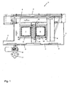
- a laser processing unit 1 for 2-station operation which has outer walls 2 and sliding doors 3 and 4 and is suitable for laser processing such as laser cutting, laser welding, hardening, etc.
- a machine frame 5 carries a boom 6, to which a in the FIG. 1 not shown laser processing head is mounted.
- the laser processing head in the X, Y, Z direction over a first and a second work table 7 and 8 are positioned. Hatched are the available for the movement of the laser processing head autarkic work areas 9 and 10, which result from the required space requirements of the boom 6 and the laser processing head.
- a user 11 can carry out preparatory measures on a worktable 7 or 8, leave the workstation again through the sliding door 3 or 4 and start and execute the laser processing with the sliding door 3 or 4 closed from outside via an operating device 12 .
- an automation of the laser processing unit 1 can also be realized.
- a protective device which has a movable partition wall 13 of individual sections (see Fig. 3 ) in the manner of a revolving shutter.
- the partition wall 13 is guided at its ends 14 and 15 in guide rails.
- FIGS. 2a to 2c shows the possibilities of movement of the partition wall 13:
- the partition 13 In a first position according to Fig. 2a the partition 13 is fully extended on the working area 10 side facing.
- the work area 10 is shielded, the user could work there.
- the dividing wall 13 On the side facing the working area 9, the dividing wall 13 is sunk in a base frame 16 with base frame walls 16a and 16b , so that a working portion 17 is available for moving the arm or the laser processing head 18 .
- a second position according to Fig. 2b is the partition 13 both on the working area 9 as well as on the working area 10 side facing partially, ie half, extended. This allows a crossing of the partition wall 13 by the laser processing head 18.
- the partition 13 looks on both sides of the base frame 16 out.
- the partition wall 13 In a third position according to Fig. 2c the partition wall 13 is fully extended on the working area 9 side facing.
- the work area 9 is shielded, the user could work there.
- the dividing wall 13 On the side facing the working area 10, the dividing wall 13 is recessed in the base frame 16 of the dividing wall 13, so that the working portion 17 is available for moving the arm or the laser machining head 18.
- the working portion 17 is alternately added to the one or the other work area 9 or 10 added and made available.
- the base frame 16 is provided with rollers 16c and can be slid into the working area of the laser processing unit and subdivide it into two autonomous working areas. If necessary, the base frame 16 can be removed with the partition 13 also to a Use of the entire work area for laser machining of larger workpieces.
- the partition 13 consists of individual sections 19 which are hinged together, with connectors of the sections 19 are not shown and are formed so that the sections 19 are collapsible.
- This principle is known by shutters or roller shutters.
- teeth 20 of a drive wheel 21 of a drive unit received in the base frame can engage with a gear motor or electric motor and move the partition wall 13 in the guide rail 22 according to the double arrow 23 and therefore move up or down.
Landscapes
- Engineering & Computer Science (AREA)
- Physics & Mathematics (AREA)
- Optics & Photonics (AREA)
- Mechanical Engineering (AREA)
- Plasma & Fusion (AREA)
- Laser Beam Processing (AREA)
- Electrical Discharge Machining, Electrochemical Machining, And Combined Machining (AREA)
- Auxiliary Devices For Machine Tools (AREA)
- Lasers (AREA)
Description
- Die Erfindung betrifft eine Laserbearbeitungsschutzvorrichtung.
- Bei Laserbearbeitungseinheiten werden bisher starre, verschiebbare Türen als Schutzvorrichtung und/oder zur Unterteilung von autarken Arbeitsbereichen eingesetzt. Die Türen sind verschiebbar angeordnet, damit ein Ausleger und/oder ein Laserbearbeitungskopf den Arbeitsbereich wechseln kann. In dem einen Arbeitsbereich finden vorbereitende Maßnahmen und in dem anderen Arbeitsbereich finden gleichzeitig Laserbearbeitungen statt.
- Durch die
DE 9319380 U1 ist ein Brecher für Gestein und/oder Recyclingmaterial mit einer Rollladen-Einhausung bekannt geworden. - Es soll die Aufgabe gelöst werden, eine möglichst einfach aufgebaute Laserbearbeitungsschutzvorrichtung zu entwickeln, welche es gestattet, dass ein Ausleger und/oder ein Laserbearbeitungskopf den Arbeitsbereich wechseln kann.
- Diese Aufgabe wird durch eine Laserbearbeitungsschutzvorrichtung gemäß Patentanspruch 1 gelöst. Es ist ein Grundgestell mit einer U-förmigen Führung der Trennwand vorgesehen, wobei die Trennwand das Grundgestell quer zur Längsrichtung des Grundgestells durchlaufen und an den beiden Längsseiten des Grundgestells aus dem Grundgestell heraus gefahren werden kann. Wenn jeweils eine Hälfte der Trennwand in einer mittleren Stellung der Trennwand beidseitig aus dem Grundgestell heraus fahrbar ist, kann der Ausleger und/oder der Laserbearbeitungskopf die Trennwand überqueren.
- Eine Ausführung des Grundgestells mit Rollen erlaubt das Verfahren und Positionieren der Trennwand in der Laserbearbeitungseinheit.
- Zur Bewegung der Trennwand ist eine Antriebseinheit vorteilhaft.
- Ein Ausführungsbeispiel der Erfindung ist in der Zeichnung schematisch dargestellt und wird nachfolgend mit Bezug zu den Figuren der Zeichnung näher erläutert. Es zeigt im Einzelnen:
- Fig. 1
- eine Draufsicht einer Laserbearbeitungseinheit;
- Fig. 2a bis 2c
- eine Seitenansicht der Schutzvorrichtung der Laserbearbeitungseinheit;
- Fig. 3
- einen vergrößerten Ausschnitt einer Trennwand der Schutzvorrichtung.
- Aus der
Fig. 1 ist der Aufbau einer Laserbearbeitungseinheit 1 für einen 2-Stationenbetrieb ersichtlich, welche äußere Wä fünf nde 2 und Schiebetüren 3 und 4 aufweist und zum Laserbearbeiten, wie Laserschneiden, Laserschweißen, Härten etc., geeignet ist. Ein Maschinenrahmen 5 trägt einen Ausleger 6, an dem ein in derFigur 1 nicht gezeigter Laserbearbeitungskopf angebracht ist. Mithilfe des Auslegers 6 kann der Laserbearbeitungskopf in X-, Y-, Z-Richtung über einem ersten und einem zweiten Arbeitstisch 7 und 8 positioniert werden. Schraffiert eingezeichnet sind die für die Bewegung des Laserbearbeitungskopfs zur Verfügung stehenden autarken Arbeitsbereiche 9 und 10, welche sich aus dem benötigten Platzbedarf des Auslegers 6 und des Laserbearbeitungskopfs ergeben. - Beim Betrieb der Laserbearbeitungseinheit 1 kann ein Anwender 11 an einem Arbeitstisch 7 oder 8 vorbereitende Maßnahmen durchführen, den Arbeitsplatz durch die Schiebetür 3 oder 4 wieder verlassen und die Laserbearbeitung bei geschlossener Schiebetür 3 oder 4 von außen über eine Bedieneinrichtung 12 geschützt starten und durchführen. Es kann aber auch eine Automatisierung der Laserbearbeitungseinheit 1 verwirklicht sein.
- Wenn ein Werkstück auf einem Arbeitstisch 7 oder 8 bearbeitet werden soll, muss der Laserbearbeitungskopf einerseits aus einem Arbeitsbereich 9 oder 10 in den anderen wechseln. Andererseits können Vorbereitungen in einem Arbeitsbereich 9 oder 10 von dem Anwender 11 nur durchgeführt werden, wenn der Arbeitsbereich 9 oder 10 gegen eine Laserstrahlung geschützt ist. Hierzu ist eine Schutzvorrichtung vorgesehen, welche eine bewegbare Trennwand 13 aus einzelnen Sektionen (siehe
Fig. 3 ) in der Art eines umlaufenden Rollladens aufweist. Die Trennwand 13 ist an ihren Enden 14 und 15 in Führungsschienen geführt. Somit kann in dem einen Arbeitsbereich eine Laserbearbeitung stattfinden, während in dem anderen Arbeitsbereich gerüstet werden kann. - Die Abfolge der
Figuren 2a bis 2c zeigt die Bewegungsmöglichkeiten der Trennwand 13: - In einer ersten Stellung gemäß
Fig. 2a ist die Trennwand 13 vollständig auf der dem Arbeitsbereich 10 zugewandten Seite ausgefahren. Der Arbeitsbereich 10 ist abgeschirmt, der Anwender könnte dort arbeiten. Auf der dem Arbeitsbereich 9 zugewandten Seite ist die Trennwand 13 in einem Grundgestell 16 mit Grundgestellwänden 16a und 16b versenkt, so dass ein Arbeitsteilbereich 17 zur Bewegung des Auslegers oder des Laserbearbeitungskopfs 18 zur Verfügung steht. - In einer zweiten Stellung gemäß
Fig. 2b ist die Trennwand 13 sowohl auf der dem Arbeitsbereich 9 als auch auf der dem Arbeitsbereich 10 zugewandten Seite teilweise, d. h. zur Hälfte, ausgefahren. Dies erlaubt eine Überquerung der Trennwand 13 durch den Laserbearbeitungskopf 18. Die Trennwand 13 schaut beidseitig aus dem Grundgestell 16 heraus. - In einer dritten Stellung gemäß
Fig. 2c ist die Trennwand 13 vollständig auf der dem Arbeitsbereich 9 zugewandten Seite ausgefahren. Der Arbeitsbereich 9 ist abgeschirmt, der Anwender könnte dort arbeiten. Auf der dem Arbeitsbereich 10 zugewandten Seite ist die Trennwand 13 in dem Grundgestell 16 der Trennwand 13 versenkt, so dass der Arbeitsteilbereich 17 zur Bewegung des Auslegers oder des Laserbearbeitungskopfs 18 zur Verfügung steht. Der Arbeitsteilbereich 17 wird wechselweise dem einen oder dem anderen Arbeitsbereich 9 oder 10 hinzu gerechnet und zur Verfügung gestellt. - Das Grundgestell 16 ist mit Rollen 16c versehen und kann in den Arbeitsbereich der Laserbearbeitungseinheit geschoben werden und diesen in zwei autarke Arbeitsbereiche unterteilen. Bei Bedarf kann das Grundgestell 16 mit der Trennwand 13 auch entfernt werden, um eine Nutzung des gesamten Arbeitsbereichs zur Laserbearbeitung größerer Werkstücke zu ermöglichen.
- Wie in
Fig. 3 dargestellt, besteht die Trennwand 13 aus einzelnen Sektionen 19, welche gelenkig miteinander verbunden sind, wobei Verbindungsstücke der Sektionen 19 nicht gezeigt und so ausgebildet sind, dass die Sektionen 19 zusammenschiebbar sind. Dieses Prinzip an sich ist durch Rollläden oder Rolltore bekannt. In Zwischenräume der Sektionen 19 können Zähne 20 eines Antriebsrades 21 einer in dem Grundgestell aufgenommenen Antriebseinheit mit einem Getriebemotor oder Elektromotor eingreifen und die Trennwand 13 in der Führungsschiene 22 gemäß dem Doppelpfeil 23 bewegen und daher hoch oder runter fahren. -
- 1
- Laserbearbeitungseinheit
- 2
- Wand
- 3
- Schiebetür
- 4
- Schiebetür
- 5
- Maschinenrahmen
- 6
- Ausleger
- 7
- Arbeitstisch
- 8
- Arbeitstisch
- 9
- Arbeitsbereich
- 10
- Arbeitsbereich
- 11
- Anwender
- 12
- Bedieneinrichtung
- 13
- Trennwand
- 14
- Trennwandende
- 15
- Trennwandende
- 16
- Grundgestell
- 16a
- Grundgestellwand
- 16b
- Grundgestellwand
- 17
- Arbeitsteilbereich
- 18
- Laserbearbeitungskopf
- 16c
- Rolle
- 19
- Sektion
- 20
- Zahn
- 21
- Antriebsrad
- 22
- Führungsschiene
- 23
- Bewegungsrichtung
Claims (4)
- Laserbearbeitungsschutzvorrichtung mit einer in vertikaler Richtung bewegbaren Trennwand (13) aus einzelnen miteinander verbundenen Sektionen (19), dadurch gekennzeichnet, daß ein Grundgestell (16) mit einer U-förmigen Führung der Trennwand (13) vorgesehen ist, wobei die Trennwand (13) das Grundgestell (16) quer zur Längsrichtung des Grundgestells (16) durchlaufen und an den beiden Längsseiten des Grundgestells (16) aus dem Grundgestell (16) heraus gefahren werden kann.
- Schutzvorrichtung nach Anspruch 1, dadurch gekennzeichnet, dass jeweils eine Hälfte der Trennwand (13) in einer mittleren Stellung der Trennwand (13) beidseitig aus dem Grundgestell (16) heraus fahrbar ist.
- Schutzvorrichtung nach Anspruch 1 oder 2, dadurch gekennzeichnet, dass das Grundgestell (16) mit Rollen (16c) versehen ist.
- Schutzvorrichtung nach einem der vorhergehenden Ansprüche, dadurch gekennzeichnet, dass das Grundgestell (16) eine Antriebseinheit zur Bewegung der Trennwand (13) aufnimmt.
Priority Applications (6)
| Application Number | Priority Date | Filing Date | Title |
|---|---|---|---|
| EP04021785A EP1634674B1 (de) | 2004-09-14 | 2004-09-14 | Schutzvorrichtung einer Laserbearbeitungseinheit |
| AT04021785T ATE389500T1 (de) | 2004-09-14 | 2004-09-14 | Schutzvorrichtung einer laserbearbeitungseinheit |
| PL04021785T PL1634674T3 (pl) | 2004-09-14 | 2004-09-14 | Urządzenie ochronne dla jednostki obróbki laserowej |
| ES04021785T ES2303617T3 (es) | 2004-09-14 | 2004-09-14 | Sistema protector para el mecanizado por laser. |
| DE502004006590T DE502004006590D1 (de) | 2004-09-14 | 2004-09-14 | Schutzvorrichtung einer Laserbearbeitungseinheit |
| US11/226,923 US8084714B2 (en) | 2004-09-14 | 2005-09-13 | Protection device of a laser processing unit |
Applications Claiming Priority (1)
| Application Number | Priority Date | Filing Date | Title |
|---|---|---|---|
| EP04021785A EP1634674B1 (de) | 2004-09-14 | 2004-09-14 | Schutzvorrichtung einer Laserbearbeitungseinheit |
Publications (2)
| Publication Number | Publication Date |
|---|---|
| EP1634674A1 EP1634674A1 (de) | 2006-03-15 |
| EP1634674B1 true EP1634674B1 (de) | 2008-03-19 |
Family
ID=34926525
Family Applications (1)
| Application Number | Title | Priority Date | Filing Date |
|---|---|---|---|
| EP04021785A Expired - Lifetime EP1634674B1 (de) | 2004-09-14 | 2004-09-14 | Schutzvorrichtung einer Laserbearbeitungseinheit |
Country Status (6)
| Country | Link |
|---|---|
| US (1) | US8084714B2 (de) |
| EP (1) | EP1634674B1 (de) |
| AT (1) | ATE389500T1 (de) |
| DE (1) | DE502004006590D1 (de) |
| ES (1) | ES2303617T3 (de) |
| PL (1) | PL1634674T3 (de) |
Families Citing this family (8)
| Publication number | Priority date | Publication date | Assignee | Title |
|---|---|---|---|---|
| DE102013114489B3 (de) * | 2013-12-19 | 2015-04-30 | Messer Cutting Systems Gmbh | Vorrichtung für die thermische Bearbeitung eines Werkstücks |
| US10391597B2 (en) | 2014-03-31 | 2019-08-27 | Lincoln Global, Inc. | Laser workstation with endless loop conveyor and coordinated access doors |
| US10086471B2 (en) | 2014-03-31 | 2018-10-02 | Lincoln Global, Inc. | Laser enclosure with reciprocally movable shuttle structure, and method of using same |
| ITUB20159554A1 (it) * | 2015-12-15 | 2017-06-15 | Prima Ind Spa | Cella di lavoro e centro per lavorazioni laser dotato di tale cella |
| CN105460366B (zh) | 2015-12-28 | 2017-11-21 | 同方威视技术股份有限公司 | 防护装置和包括该防护装置的激光拉曼安检仪 |
| DE102016204345A1 (de) * | 2016-03-16 | 2017-09-21 | Bayerische Motoren Werke Aktiengesellschaft | Laser-Remote-Bearbeitungsanlage und Verfahren zum Betrieb einer Laser-Remote-Bearbeitungsanlage |
| JP7422146B2 (ja) * | 2018-10-16 | 2024-01-25 | エレクトロ サイエンティフィック インダストリーズ インコーポレーテッド | レーザ加工システムのためのフレーム及び外側シュラウド |
| AT523476B1 (de) * | 2020-01-27 | 2021-10-15 | Trumpf Werkzeugmaschinen Gmbh Co Kg | Bearbeitungsvorrichtung zum Bearbeiten eines oder mehrerer Werkstücke |
Family Cites Families (12)
| Publication number | Priority date | Publication date | Assignee | Title |
|---|---|---|---|---|
| US2755081A (en) * | 1951-10-08 | 1956-07-17 | Johnson Clarence | Garage door operators |
| US2936463A (en) * | 1957-10-25 | 1960-05-17 | Frank Katzentine A | Bathing enclosure |
| US4635699A (en) * | 1984-04-06 | 1987-01-13 | Covenant Manufacturing Co. | Retractable safety shield |
| US5277240A (en) * | 1990-04-24 | 1994-01-11 | Tebel Pneumatiek B.V. | Overhead door assembly |
| DE9319380U1 (de) * | 1993-12-16 | 1994-02-10 | Böhringer, Paul, 74229 Oedheim | Brecher für Gestein und/oder Recyclingmaterial |
| US5643477A (en) * | 1995-06-30 | 1997-07-01 | Motoman Inc. | Laser enclosure |
| DE19956900B4 (de) * | 1999-11-26 | 2005-09-08 | Stama Maschinenfabrik Gmbh | Werkzeugmaschine mit Faltenbalg-Dachabdeckung |
| JP4615661B2 (ja) * | 2000-02-28 | 2011-01-19 | 株式会社アマダ | レーザ加工システム及びこのレーザ加工システムを用いたレーザ加工方法 |
| DE20200664U1 (de) * | 2002-01-17 | 2002-07-25 | Kahl, Helmut, 32457 Porta Westfalica | Laserschutzwand |
| JP2003287027A (ja) * | 2002-03-28 | 2003-10-10 | Mori Seiki Co Ltd | シール構造 |
| US6708956B1 (en) * | 2002-04-03 | 2004-03-23 | Genesis Systems Group, Ltd. | Break away barrier and method for using same |
| US6772932B1 (en) * | 2002-11-25 | 2004-08-10 | Scott P. Halstead | Automated welding system utilizing overhead robots |
-
2004
- 2004-09-14 PL PL04021785T patent/PL1634674T3/pl unknown
- 2004-09-14 ES ES04021785T patent/ES2303617T3/es not_active Expired - Lifetime
- 2004-09-14 EP EP04021785A patent/EP1634674B1/de not_active Expired - Lifetime
- 2004-09-14 AT AT04021785T patent/ATE389500T1/de not_active IP Right Cessation
- 2004-09-14 DE DE502004006590T patent/DE502004006590D1/de not_active Expired - Lifetime
-
2005
- 2005-09-13 US US11/226,923 patent/US8084714B2/en not_active Expired - Fee Related
Also Published As
| Publication number | Publication date |
|---|---|
| ATE389500T1 (de) | 2008-04-15 |
| PL1634674T3 (pl) | 2008-08-29 |
| EP1634674A1 (de) | 2006-03-15 |
| DE502004006590D1 (de) | 2008-04-30 |
| US8084714B2 (en) | 2011-12-27 |
| US20060076322A1 (en) | 2006-04-13 |
| ES2303617T3 (es) | 2008-08-16 |
Similar Documents
| Publication | Publication Date | Title |
|---|---|---|
| EP2353820B2 (de) | Holzbearbeitungsanlage | |
| DE1427765C3 (de) | Führungseinrichtung für eine Betonschneidmaschine | |
| EP2185317B1 (de) | Werkzeugmaschine mit mindestens einer schiebetüre | |
| DE202014010665U1 (de) | Maschine zur maschinellen Bearbeitung von Wänden, insbesondere für Wände aus Holz oder mehrschichtige Wände und dergleichen | |
| DE4331090C2 (de) | Spritzschutzeinrichtung für eine Werkzeugmaschine | |
| EP1634674A1 (de) | Schutzvorrichtung einer Laserbearbeitungseinheit | |
| EP1840448A1 (de) | Variable Schutzkabine | |
| DE102007057407A1 (de) | Maschine zum Fräsen des Längsprofils der Schäfte von Schlüsseln für Zylinderschlösser und Verfahren zur Bearbeitung von Schäften an Schlüsseln für Zylinderschlösser durch Fräsen | |
| EP0605773A2 (de) | Vorrichtung zum Bearbeiten der Eckverbindungen von Rahmen | |
| EP0460654A1 (de) | Vorrichtung zum Bearbeiten von Fensterrahmen o. dgl. | |
| EP3558608B1 (de) | Vorrichtung zum bearbeiten von stangenförmigen werkstücken wie fensterprofile oder türprofile | |
| DE2809152C3 (de) | Bohr-Fräsvorrichtung zum Einarbeiten von Schlitzen | |
| DE2726382C3 (de) | Vorrichtung zum Bohren und Ausschneiden oder Fräsen eines Bauteiles aus einem plattenförmigen Werkstück aus Holz o.dgl | |
| DE3817005C2 (de) | Schweißmaschine zur Herstellung von Rahmen | |
| DE202011002384U1 (de) | Holzbearbeitungsanlage in Portalbauweise | |
| EP0292864B1 (de) | Holzbearbeitungsmaschine | |
| EP0697936B1 (de) | Steinsäge mit schutzgehäusedrehtür- werkstückauflagetisch-kombination | |
| DE2513620A1 (de) | Vorrichtung zur eckenbearbeitung von kunststoffprofilrahmen | |
| DE102023005414A1 (de) | Verfahren zum Kantenfräsen | |
| DE4406381A1 (de) | Maschine zur Bearbeitung von stabförmigen Werkstücken | |
| DE10025354C2 (de) | Abdeckvorrichtung für eine Werkzeugmaschine | |
| DE102021121576B4 (de) | Maschine für das Fräsen oder Schleifen von Zahnstangen | |
| DE4308233A1 (de) | Arbeitsmaschine, insbesondere für die Endbearbeitung von Oberflächen von Werkstücken | |
| DE19505107C2 (de) | Abdeckhaube für eine Werkzeugmaschine zum Bearbeiten von Profilen, Stäben oder dergleichen | |
| DE1962320A1 (de) | Verfahren zum Herstellen in kontinuierlichem Fluss von Schalungsplatten und Vorrichtung zur Durchfuehrung dieses Verfahrens sowie mit dem neuen Verfahren hergestellte Schalungsplatte |
Legal Events
| Date | Code | Title | Description |
|---|---|---|---|
| PUAI | Public reference made under article 153(3) epc to a published international application that has entered the european phase |
Free format text: ORIGINAL CODE: 0009012 |
|
| 17P | Request for examination filed |
Effective date: 20050310 |
|
| AK | Designated contracting states |
Kind code of ref document: A1 Designated state(s): AT BE BG CH CY CZ DE DK EE ES FI FR GB GR HU IE IT LI LU MC NL PL PT RO SE SI SK TR |
|
| AX | Request for extension of the european patent |
Extension state: AL HR LT LV MK |
|
| AKX | Designation fees paid |
Designated state(s): AT BE BG CH CY CZ DE DK EE ES FI FR GB GR HU IE IT LI LU MC NL PL PT RO SE SI SK TR |
|
| 17Q | First examination report despatched |
Effective date: 20061103 |
|
| GRAP | Despatch of communication of intention to grant a patent |
Free format text: ORIGINAL CODE: EPIDOSNIGR1 |
|
| GRAS | Grant fee paid |
Free format text: ORIGINAL CODE: EPIDOSNIGR3 |
|
| GRAA | (expected) grant |
Free format text: ORIGINAL CODE: 0009210 |
|
| AK | Designated contracting states |
Kind code of ref document: B1 Designated state(s): AT BE BG CH CY CZ DE DK EE ES FI FR GB GR HU IE IT LI LU MC NL PL PT RO SE SI SK TR |
|
| REG | Reference to a national code |
Ref country code: GB Ref legal event code: FG4D Free format text: NOT ENGLISH |
|
| REG | Reference to a national code |
Ref country code: CH Ref legal event code: EP |
|
| REF | Corresponds to: |
Ref document number: 502004006590 Country of ref document: DE Date of ref document: 20080430 Kind code of ref document: P |
|
| REG | Reference to a national code |
Ref country code: IE Ref legal event code: FG4D Free format text: LANGUAGE OF EP DOCUMENT: GERMAN |
|
| PG25 | Lapsed in a contracting state [announced via postgrant information from national office to epo] |
Ref country code: FI Free format text: LAPSE BECAUSE OF FAILURE TO SUBMIT A TRANSLATION OF THE DESCRIPTION OR TO PAY THE FEE WITHIN THE PRESCRIBED TIME-LIMIT Effective date: 20080319 |
|
| REG | Reference to a national code |
Ref country code: ES Ref legal event code: FG2A Ref document number: 2303617 Country of ref document: ES Kind code of ref document: T3 |
|
| REG | Reference to a national code |
Ref country code: PL Ref legal event code: T3 |
|
| NLV1 | Nl: lapsed or annulled due to failure to fulfill the requirements of art. 29p and 29m of the patents act | ||
| PG25 | Lapsed in a contracting state [announced via postgrant information from national office to epo] |
Ref country code: SI Free format text: LAPSE BECAUSE OF FAILURE TO SUBMIT A TRANSLATION OF THE DESCRIPTION OR TO PAY THE FEE WITHIN THE PRESCRIBED TIME-LIMIT Effective date: 20080319 |
|
| REG | Reference to a national code |
Ref country code: IE Ref legal event code: FD4D |
|
| PG25 | Lapsed in a contracting state [announced via postgrant information from national office to epo] |
Ref country code: PT Free format text: LAPSE BECAUSE OF FAILURE TO SUBMIT A TRANSLATION OF THE DESCRIPTION OR TO PAY THE FEE WITHIN THE PRESCRIBED TIME-LIMIT Effective date: 20080826 Ref country code: SE Free format text: LAPSE BECAUSE OF FAILURE TO SUBMIT A TRANSLATION OF THE DESCRIPTION OR TO PAY THE FEE WITHIN THE PRESCRIBED TIME-LIMIT Effective date: 20080619 Ref country code: SK Free format text: LAPSE BECAUSE OF FAILURE TO SUBMIT A TRANSLATION OF THE DESCRIPTION OR TO PAY THE FEE WITHIN THE PRESCRIBED TIME-LIMIT Effective date: 20080319 |
|
| PG25 | Lapsed in a contracting state [announced via postgrant information from national office to epo] |
Ref country code: RO Free format text: LAPSE BECAUSE OF FAILURE TO SUBMIT A TRANSLATION OF THE DESCRIPTION OR TO PAY THE FEE WITHIN THE PRESCRIBED TIME-LIMIT Effective date: 20080319 Ref country code: NL Free format text: LAPSE BECAUSE OF FAILURE TO SUBMIT A TRANSLATION OF THE DESCRIPTION OR TO PAY THE FEE WITHIN THE PRESCRIBED TIME-LIMIT Effective date: 20080319 |
|
| ET | Fr: translation filed | ||
| PLBE | No opposition filed within time limit |
Free format text: ORIGINAL CODE: 0009261 |
|
| STAA | Information on the status of an ep patent application or granted ep patent |
Free format text: STATUS: NO OPPOSITION FILED WITHIN TIME LIMIT |
|
| PG25 | Lapsed in a contracting state [announced via postgrant information from national office to epo] |
Ref country code: IE Free format text: LAPSE BECAUSE OF FAILURE TO SUBMIT A TRANSLATION OF THE DESCRIPTION OR TO PAY THE FEE WITHIN THE PRESCRIBED TIME-LIMIT Effective date: 20080319 Ref country code: DK Free format text: LAPSE BECAUSE OF FAILURE TO SUBMIT A TRANSLATION OF THE DESCRIPTION OR TO PAY THE FEE WITHIN THE PRESCRIBED TIME-LIMIT Effective date: 20080319 |
|
| 26N | No opposition filed |
Effective date: 20081222 |
|
| BERE | Be: lapsed |
Owner name: TRUMPF WERKZEUGMASCHINEN G.M.B.H. + CO. KG Effective date: 20080930 |
|
| PG25 | Lapsed in a contracting state [announced via postgrant information from national office to epo] |
Ref country code: BG Free format text: LAPSE BECAUSE OF FAILURE TO SUBMIT A TRANSLATION OF THE DESCRIPTION OR TO PAY THE FEE WITHIN THE PRESCRIBED TIME-LIMIT Effective date: 20080619 Ref country code: MC Free format text: LAPSE BECAUSE OF NON-PAYMENT OF DUE FEES Effective date: 20080930 Ref country code: EE Free format text: LAPSE BECAUSE OF FAILURE TO SUBMIT A TRANSLATION OF THE DESCRIPTION OR TO PAY THE FEE WITHIN THE PRESCRIBED TIME-LIMIT Effective date: 20080319 |
|
| GBPC | Gb: european patent ceased through non-payment of renewal fee |
Effective date: 20080914 |
|
| PG25 | Lapsed in a contracting state [announced via postgrant information from national office to epo] |
Ref country code: BE Free format text: LAPSE BECAUSE OF NON-PAYMENT OF DUE FEES Effective date: 20080930 |
|
| PG25 | Lapsed in a contracting state [announced via postgrant information from national office to epo] |
Ref country code: CY Free format text: LAPSE BECAUSE OF FAILURE TO SUBMIT A TRANSLATION OF THE DESCRIPTION OR TO PAY THE FEE WITHIN THE PRESCRIBED TIME-LIMIT Effective date: 20080319 |
|
| PG25 | Lapsed in a contracting state [announced via postgrant information from national office to epo] |
Ref country code: AT Free format text: LAPSE BECAUSE OF NON-PAYMENT OF DUE FEES Effective date: 20080914 |
|
| PG25 | Lapsed in a contracting state [announced via postgrant information from national office to epo] |
Ref country code: GB Free format text: LAPSE BECAUSE OF NON-PAYMENT OF DUE FEES Effective date: 20080914 |
|
| PG25 | Lapsed in a contracting state [announced via postgrant information from national office to epo] |
Ref country code: HU Free format text: LAPSE BECAUSE OF FAILURE TO SUBMIT A TRANSLATION OF THE DESCRIPTION OR TO PAY THE FEE WITHIN THE PRESCRIBED TIME-LIMIT Effective date: 20080920 Ref country code: LU Free format text: LAPSE BECAUSE OF NON-PAYMENT OF DUE FEES Effective date: 20080914 |
|
| PG25 | Lapsed in a contracting state [announced via postgrant information from national office to epo] |
Ref country code: GR Free format text: LAPSE BECAUSE OF FAILURE TO SUBMIT A TRANSLATION OF THE DESCRIPTION OR TO PAY THE FEE WITHIN THE PRESCRIBED TIME-LIMIT Effective date: 20080620 |
|
| REG | Reference to a national code |
Ref country code: FR Ref legal event code: PLFP Year of fee payment: 13 |
|
| REG | Reference to a national code |
Ref country code: FR Ref legal event code: PLFP Year of fee payment: 14 |
|
| REG | Reference to a national code |
Ref country code: FR Ref legal event code: PLFP Year of fee payment: 15 |
|
| PGFP | Annual fee paid to national office [announced via postgrant information from national office to epo] |
Ref country code: CZ Payment date: 20210914 Year of fee payment: 18 Ref country code: CH Payment date: 20210920 Year of fee payment: 18 Ref country code: FR Payment date: 20210921 Year of fee payment: 18 Ref country code: IT Payment date: 20210922 Year of fee payment: 18 |
|
| PGFP | Annual fee paid to national office [announced via postgrant information from national office to epo] |
Ref country code: PL Payment date: 20210819 Year of fee payment: 18 Ref country code: DE Payment date: 20210920 Year of fee payment: 18 Ref country code: TR Payment date: 20210913 Year of fee payment: 18 |
|
| PGFP | Annual fee paid to national office [announced via postgrant information from national office to epo] |
Ref country code: ES Payment date: 20211119 Year of fee payment: 18 |
|
| REG | Reference to a national code |
Ref country code: DE Ref legal event code: R119 Ref document number: 502004006590 Country of ref document: DE |
|
| PG25 | Lapsed in a contracting state [announced via postgrant information from national office to epo] |
Ref country code: CZ Free format text: LAPSE BECAUSE OF NON-PAYMENT OF DUE FEES Effective date: 20220914 |
|
| REG | Reference to a national code |
Ref country code: CH Ref legal event code: PL |
|
| PG25 | Lapsed in a contracting state [announced via postgrant information from national office to epo] |
Ref country code: LI Free format text: LAPSE BECAUSE OF NON-PAYMENT OF DUE FEES Effective date: 20220930 Ref country code: FR Free format text: LAPSE BECAUSE OF NON-PAYMENT OF DUE FEES Effective date: 20220930 Ref country code: DE Free format text: LAPSE BECAUSE OF NON-PAYMENT OF DUE FEES Effective date: 20230401 Ref country code: CH Free format text: LAPSE BECAUSE OF NON-PAYMENT OF DUE FEES Effective date: 20220930 |
|
| REG | Reference to a national code |
Ref country code: ES Ref legal event code: FD2A Effective date: 20231027 |
|
| PG25 | Lapsed in a contracting state [announced via postgrant information from national office to epo] |
Ref country code: IT Free format text: LAPSE BECAUSE OF NON-PAYMENT OF DUE FEES Effective date: 20220914 |
|
| PG25 | Lapsed in a contracting state [announced via postgrant information from national office to epo] |
Ref country code: ES Free format text: LAPSE BECAUSE OF NON-PAYMENT OF DUE FEES Effective date: 20220915 |
|
| PG25 | Lapsed in a contracting state [announced via postgrant information from national office to epo] |
Ref country code: ES Free format text: LAPSE BECAUSE OF NON-PAYMENT OF DUE FEES Effective date: 20220915 |
|
| PG25 | Lapsed in a contracting state [announced via postgrant information from national office to epo] |
Ref country code: PL Free format text: LAPSE BECAUSE OF NON-PAYMENT OF DUE FEES Effective date: 20220914 |
|
| PG25 | Lapsed in a contracting state [announced via postgrant information from national office to epo] |
Ref country code: TR Free format text: LAPSE BECAUSE OF NON-PAYMENT OF DUE FEES Effective date: 20220914 |