EP1634533A1 - Optisches fettmessgerät - Google Patents
Optisches fettmessgerät Download PDFInfo
- Publication number
- EP1634533A1 EP1634533A1 EP04746033A EP04746033A EP1634533A1 EP 1634533 A1 EP1634533 A1 EP 1634533A1 EP 04746033 A EP04746033 A EP 04746033A EP 04746033 A EP04746033 A EP 04746033A EP 1634533 A1 EP1634533 A1 EP 1634533A1
- Authority
- EP
- European Patent Office
- Prior art keywords
- light
- section
- light receiving
- light source
- receiving section
- Prior art date
- Legal status (The legal status is an assumption and is not a legal conclusion. Google has not performed a legal analysis and makes no representation as to the accuracy of the status listed.)
- Withdrawn
Links
Images


Classifications
-
- A—HUMAN NECESSITIES
- A61—MEDICAL OR VETERINARY SCIENCE; HYGIENE
- A61B—DIAGNOSIS; SURGERY; IDENTIFICATION
- A61B5/00—Measuring for diagnostic purposes; Identification of persons
- A61B5/48—Other medical applications
- A61B5/4869—Determining body composition
- A61B5/4872—Body fat
-
- A—HUMAN NECESSITIES
- A61—MEDICAL OR VETERINARY SCIENCE; HYGIENE
- A61B—DIAGNOSIS; SURGERY; IDENTIFICATION
- A61B5/00—Measuring for diagnostic purposes; Identification of persons
- A61B5/0059—Measuring for diagnostic purposes; Identification of persons using light, e.g. diagnosis by transillumination, diascopy, fluorescence
Definitions
- the present invention relates to an optical fat measuring apparatus capable of optically measuring subcutaneous fat, as well as a standard element.
- a light source section and a light receiving section are arranged on the skin in a straight line, and the light source emits a near infrared light. Then, the light receiving section receives a light transmitted through the fat layer. The quantity of light received by the light receiving section is applied to a calibration curve for the quantity of light received and the thickness of the fat to estimate the thickness of the fat.
- a light propagation characteristic varies significantly between the muscle and the fat. More light is absorbed by the muscle, whereas light is more markedly scattered by the fat. This difference in characteristic is significant for a light having a wavelength of 500 to 1,000 nm.
- the thicker the subcutaneous fat layer is the more widely the light emitted by the light source and entering the surface of the living body is spread.
- the light is diffusively spread not only in the direction of the depth but also in a lateral direction. Accordingly, the quantity of light laterally spread and exiting the surface of the living body again increases consistently with the thickness of the subcutaneous fat. Therefore, the thickness and amount of subcutaneous fat can be measured by using the light receiving section to receive light.
- the light source section and the light receiving section are arranged so as to obtain a plurality of transmitted to received height distances, in order to correct the color of the skin or the like. This makes it possible to accurately measure the thickness of the subcutaneous fat. Specifically, when the quantity of light received by the light receiving section is determined, the quantity of light received by each light receiving section, which is dependent on the skin color difference, is corrected by the quantity of light received by the light receiving element closest to the light source section.
- a protective cover is placed so that a surface of the protective cover which has a reflector lies opposite a surface of the device which has a light source section and a light receiving section.
- the light source section emits light
- the reflector of the protective cover reflects the light.
- the quantity of light incident on the light receiving section is measured.
- the measured quantity of light received is used as reference data on the percentage of body fat.
- the light source used is a near infrared light, which is less visible tohumanbeings, even if an emission end of the light source section is contaminated and thus has a significantly reduced output, the user fails to notice this while using the device. As a result, disadvantageously, the accuracy decreases.
- the method according to Japanese Patent No. 2648377 uses the reflector attached to the protective cover. This calibration is effective if the light receiving section and the light source are located close to each other or at the same transmitted to received light distance.
- a signal level resulting from measurement of the living body varies exponentially with the transmitted to received light distances. Accordingly, with the simple specified reflector configuration, it is difficult to reproduce the exponentially varying quantity of light.
- the protective cover with the reflector described in Japanese Patent No. 2648377 is placed opposite the one light source and plurality of light receiving sections and light emitted by the light source section and then reflected by the reflector is received by the light receiving sections, the quantity of light received by the light receiving section is almost the same for all the light receiving sections. Accordingly, a light receiving section placed farther from the light source section has an excessively large amount of incident light and may thus be saturated. In contrast, if the quantity of light is adjusted for the light receiving section located farthest from the light source section to receive an optimal quantity of incident light, a light receiving section placed closer to the light source section has an excessively small quantity of incident light and cannot sense the quantity of incident light. With such a simple reflector configuration, it is difficult to reproduce an exponentially varying quantity of light.
- a first invention is an optical fat measuring apparatus comprising:
- a second invention is the optical fat measuring apparatus according to the first invention, having one of said light source sections and a plurality of said light receiving sections, and wherein said apparatus comprises an operation checking section which compares a reference value for the quantity of light received predetermined for each said light receiving section with the quantity of received light which has been guided from lighted said light source section to the plurality of said light receiving sections through said waveguide after said standard element has been placed so that said waveguide is opposite said light source section and said light receiving sections, which operates if the quantities of light received by a smaller number of said light receiving sections than that of the plurality of said light receiving sections are smaller than said reference value for the quantity of light received corresponding to these light receiving sections, to determine that these light receiving sections are defective, and which operates if each quantities of light received by all of the plurality of said light receiving sections are smaller than the reference value for the quantity of light received corresponding to said each light receiving sections, to determine that said light source section is defective.
- a third invention is the optical fat measuring apparatus according to the first invention, wherein if said operation checking section determines that said light receiving section is defective, said operation checking section shows that said light receiving section determined to be defective must be cleaned or provides a corresponding sound output, and if said operation checking section determines that said light source section is defective, said operation checking section shows that said light source section determined to be defective must be cleaned or provides a corresponding sound output.
- a fourth invention is the optical fat measuring apparatus according to the first invention, having a plurality of said light source sections and one said light receiving section, and wherein the apparatus comprises an operation checking section which compares a reference value for the quantity of light receivedpredetermined for each said light source section with the quantity of received light which has been guided from the independently lighted plurality of said light source sections to said light receiving section through said waveguide after said standard element has been placed so that said waveguide is opposite said light source sections and said light receiving section, which operates if the quantities of light received from a smaller number of said light source sections than that of the plurality of said light source sections are smaller than said reference value for the quantity of light received corresponding to these light source sections, to determine that these light source sections are defective, and which operates if each quantities of light received from all of the plurality of said light source sections are smaller than the reference value for the quantity of light received corresponding to said each light source sections, to determine that said light receiving section is defective.
- a fifth invention is the optical fat measuring apparatus according to the first invention, wherein if said operation checking section determines that said light source section is defective, said operation checking section shows that said light source section determined to be defective must be cleaned or provides a corresponding sound output, and if said operation checking section determines that said light receiving section is defective, said operation checking section shows that said light receiving section determined to be defective must be cleaned or provides a corresponding sound output.
- a sixth invention is the optical fat measuring apparatus according to the first invention, having one of said light source section and a plurality of said light receiving sections, and wherein said arithmetic section has a correcting section which corrects measured values for said living body using the quantity of received light which has been guided from lighted said light source section to the plurality of said light receiving sections through said waveguide after said standard element has been placed so that said waveguide is opposite said light source section and said light receiving sections.
- a seventh invention is the optical fat measuring apparatus according to the first invention, having a plurality of said light source sections and one said light receiving section, and wherein said arithmetic section has a correcting section which corrects measured values for said living body using the quantity of received light which has been guided from independently lighted plurality of said light source sections to said light receiving section through said waveguide after said standard element has been placed so that said waveguide is opposite said light source sections and said light receiving section.
- a eighth invention is the optical fat measuring apparatus according to the sixth invention, wherein said light receiving section includes a first light receiving section and a second light receiving section, and after said standard element has been placed so that said waveguide is opposite said light source section and said light receiving sections, said correcting section corrects the measured values for said living body on the basis of the ratio of the quantity of light received by said first light receiving section, the light being guided from lighted said light source and to said first light receiving section through said waveguide, to the quantity of light received by said second light receiving section, the light being guided from lighted said light source to said second light receiving section through said waveguide.
- a ninth invention is the optical fat measuring apparatus according to the seventh invention, wherein said light source section includes a first light source section and a second light source section, and after said standard element has been placed so that said waveguide is opposite said light source sections and said light receiving section, said correcting section corrects the measured values for said living body on the basis of the ratio of the quantity of received light guided from independently lighted said first light source to said light receiving section through said waveguide, to the quantity of received light guided from independently lighted said second light source to said light receiving section through said waveguide.
- a tenth invention is the optical fat measuring apparatus according to anyone of the first to the ninth invention, wherein said standard element is connected by a rotating shaft to a main body with said light source section and said light receiving section.
- An eleventh invention is a standard element comprising a waveguide which can be placed opposite a light source section and a light receiving section of the optical fat measuring apparatus and which guides light from said light source section to said light receiving section when placed opposite said light source section and said light receiving section of said optical fat measuring apparatus, said waveguide having a predetermined transmittance.
- a twelfth invention is the standard element according to the eleventh invention wherein said waveguide is a scatterer which scatters light or an absorber which absorbs light.
- a thirteenth invention is the standard element according to the eleventh invention wherein a reflecting layer is provided in the parts of said waveguide other than its surface opposite said light source section and said light receiving section when said standard element is placed so that said waveguide is opposite said light source section and said light receiving section.
- a fourteenth invention is the standard element according to the eleventh invention wherein a space is provided between said waveguide and said light source section and said light receiving section when said standard element is placed so that said waveguide is opposite said light source section and said light receiving section.
- a fifteenth invention is the standard element according to the fourteenth invention wherein said waveguide partly has a concave portion and said concave portion forms said space.
- a sixteenth invention is the standard element according to the eleventh invention wherein said standard element has a protective cover which covers the parts of said waveguide other than its surface opposite said light source section and said light receiving section.
- a seventeenth invention is a method of optically measuring fat, said method of making measurement using an optical fat measuring apparatus comprising:
- An eighteenth invention is a method of optically measuring fat, said method of making measurement using an optical fat measuring apparatus comprising:
- a nineteenth invention is a method of optically measuring fat, said method of making measurement using an optical fat measuring apparatus comprising:
- a twentieth invention is a method of optically measuring fat, said method of making measurement using an optical fat measuring apparatus comprising:
- An optical fat measuring apparatus comprises one light source section and a plurality of light receiving sections arranged so as to obtain a plurality of transmitted to received light distances.
- the apparatus calculates information on fat on the basis of the quantity of light received by the light receiving sections with respect to each transmitted to received light distance.
- the apparatus has a waveguide provided in a protective cover that blocks light, the waveguide having a specified transmittance. Before measurement is started and when an operation checking section is covered with the protective cover, the light source is lighted.
- the apparatus compares a reference value predetermined as a reference with the quantity of light received by each of the plurality of light receiving sections after the light propagating through the waveguide in the protective cover.
- the apparatus senses a defect in this light receiving section. The apparatus then shows that this light receiving section must be cleaned or auditorily outputs the need for cleaning. If the quantities of light received by all the light receiving sections are small, the apparatus senses a defect in the light source. The apparatus then shows that this light source must be cleaned or auditorily outputs the need for cleaning. It is thus possible to inform a user of the defect and measures to be taken. Consequently, accurate fat measurements are always possible.
- the light source is lighted. Then, on the basis of the ratio of two quantities of light received by two light receiving sections after the light propagating through the waveguide in the protective cover, degraded accuracy in measured values can be corrected which may result from a variation in the sensitivities of the plurality of light receiving sections caused by a change in temperature and a secular change. As a result, accurate fat measurements are always possible.
- an optical fat measuring apparatus comprises a plurality of light source sections and one light receiving section arranged so as to obtain a plurality of transmitted to received light distances.
- the apparatus calculates information on fat on the basis of the quantity of light received by the light receiving section with respect to each transmitted to received light distance.
- the apparatus has a waveguide provided in a protective cover that blocks light, the waveguide having a specified transmittance.
- An operation checking section individually lights each light source. The apparatus compares a reference value predetermined as a reference with the quantity of light received by the light receiving section after the light propagating through the waveguide. Then, if the quantity of light from one light source is small, the apparatus senses a defect in this light source.
- the apparatus then shows that this light source must be cleaned or auditorily outputs the need for cleaning. If the quantities of light from all the light sources are small, the apparatus senses a defect in the light receiving section. The apparatus then shows that this light receiving section must be cleaned or auditorily outputs the need for cleaning. It is thus possible to inform a user of the defect and measures to be taken. Consequently, accurate fat measurements are always possible.
- each light source is individually lighted. Then, on the basis of the ratio of two quantities of light received by the light receiving section after the light propagating through the waveguide in the protective cover, inaccuracy in measured values can be corrected which may result from a variation among outputs from the plurality of light sources caused by a change in temperature and a secular change. As a result, accurate fat measurements are always possible.
- a scattering coefficient can be used to exponentially vary the propagation of light.
- a reflection layer with a specified reflectance is formed in one of the outer surfaces of the waveguide on which the light source and the light receiving section do not face each other. This increases the propagance of the waveguide and enables the volume of the waveguide to be reduced. As a result, the size of the whole apparatus can be reduced.
- a space is provided in a site where the waveguide, the light source section, and the light receiving section face one another. Then, when the light source and the light receiving section are contaminated, the contamination can be prevented from adhering to the light receiving section. Therefore, operation checks and corrections can always correctly be executed.
- the light blocking protective cover is connected, via a rotating shaft, to a main body having the light source and light receiving section. Therefore, if the living body is measured, the removed protective cover is unlikely to be lost.
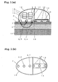
- Figure 1(a) is a diagram showing the configuration of an optical fat measuring apparatus according to Embodiment 1 of the present invention.
- Figure 1(b) is a diagram of the optical fat measuring apparatus according to Embodiment 1 as viewed from a living body.
- a light source 2 and a light receiving section 3 are provided on a surface that contacts with a surface 1 of a living body.
- the light receiving section 3 consists of a measuring light receiving section 4 and a correcting light receiving section 5.
- the distance between the measuring light receiving section 4 and the light source 2 is 38 mm. That between the correcting light receiving section 5 and the light source 2 is 23 mm.
- a port from which light emitted by the light source 2 is emitted has a distance ⁇ of 3 mm. Ports in the measuring light receiving section 4 and correcting light receiving section 5 on which light is incident have a distance ⁇ of 3 mm.
- the distance between the measuring light receiving section 4 and the light source 2 is preferably between 35 and 80 mm.
- the distance between the correcting light receiving section 5 and the light source 2 is preferably between 15 and 30 mm.
- the present apparatus is brought into contact with the living body surface 1.
- the correcting light receiving section 5 receives a quantity of light to be corrected Y1
- the measuring light receiving section 4 receives a quantity of light to be measured Y2.
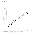
- Figure 2 shows the relationship between the thickness of subcutaneous fat 6 and a parameter Y2/Y1 corresponding to a division of the quantity of received light to be measured Y2 by the quantity of received light to be corrected Y1.
- black circles show the relationship between the Y2/Y1 and the thickness of the subcutaneous fat 6.
- the use of the Y2/Y1 enables the effect on the skin 7 to be corrected and also enables the thickness of the subcutaneous fat 6 to be accurately measured. That is, the use of the Y2/Y1 enables the thickness of the subcutaneous fat 6 to be accurately measured in spite of a variation in the color of the skin 7.
- the light source 2 uses a LED with a central wavelength of 680 nm as a light source element.
- the light source element is preferably a laser diode or LED with a central wavelength of 500 to 1,000 nm because of their characteristics showing a large difference in light propagation characteristic between the fat and the muscle.
- the apparatus is configured so that light is guided from the light source element to the living body surface 1 using a light guiding part such as an optical fiber. This is because heat generated by the light source element is not transmitted to the living body surface.
- the light receiving section 3 uses a photo diode as a light receiving element.
- the light receiving element may be a photoelectric converting element such as CdS.
- the apparatus is configured so that light is guided from the living body surface 1 to the light receiving element using a light guiding part such as an optical fiber.
- An arithmetic section 8 calculates the thickness of the subcutaneous fat 6 on the basis of the Y2/Y1 using the relationship in Figure 2.
- the calculated thickness of the subcutaneous fat 6 is displayed in the display section 9 and is sent to another equipment as data through a communication section 10.
- data such as the height, weight, age, sex, and measured site are inputted directly from an input section 11 or through a communication section 10 from other devices. Then, the arithmetic section 8 calculates the percentage of body fat correlated with the thickness of the subcutaneous fat 6. The percentage of body fat can be displayed on the display section 9 or the data can be transferred to the equipment through the communication section 10.
- the optical fat measuring apparatus has a light blocking protective cover 13 that covers the light source 2 and the light receiving section 3.
- a waveguide 14 formed of a scatterer such as high-density polyethylene is placed inside the protective cover 13.
- Recesses 15 are formed in a site of the waveguide 14 which faces the light source 2 and light receiving section 3 as shown in Figures 1(a) and 1(b).
- the protective cover is closed, the light source 2 and the light receiving section 3 do not contact tightly with the waveguide 14.
- Such a structure prevents the waveguide 14 from being contaminated even if the light source 2 and the light receiving section 3 are contaminated. Thus, accurate operation checks and corrections are always possible.
- the waveguide 14 may be composed of a combination of a first waveguide connecting the light source 2 and the measuring light receiving section 4 and a second waveguide connecting the light source 2 and the correcting light receiving section 5.
- the waveguide 14 may be an optical fiber composed of materials such as an infrared (heat ray) absorbing glass which has a specified absorptivity. If the waveguide 14 is an optical fiber, a reduced quantity of light leaking from the waveguide 14 or environmental light such as sunlight enters the waveguide 14. Consequently, the protective cover need not block light.
- the scatterer may be polycarbonate.
- polycarbonate of a light diffusion grade is useful because diffused rays have an increased transmittance.
- the protective cover 13 After the protective cover 13 has been mounted, that is, the protective cover 13 has been placed around the light source 2 and the light receiving section 3 with the waveguide 14 placed opposite the light source 2 and light receiving section 3 as shown in Figure 3, the light source 2 is lighted. The light propagates through the waveguide 14 and is then received by the light receiving section 3.
- the operation checking section 16 compares the quantity of light received by the light receiving section 3 with a reference value predetermined for each light receiving section as a reference. The reference value is prestored in a memory provided in the operation checking section 16.
- the operation checking section 16 compares the quantity of light received by the measuring light receiving section 4 with the reference value predetermined for the measuring light receiving section 4 as a reference.
- the operation checking section 16 also compares the quantity of light received by the correcting light receiving section 5 with the reference value predetermined for the correcting light receiving section 5 as a reference.
- the operation checking section 16 determines that this light receiving section is defective. Then, a display section 9 shows that the light receiving section must be cleaned. Once the display section 9 shows that the light receiving section must be cleaned, the user of the optical fat measuring apparatus cleans the light receiving section for which the need for cleaning is displayed. Further, if the quantities of light received by all the light receiving sections are small, the operation checking section 16 determines that the light source 2 is defective. Then, the display section 9 shows that the light source 2 must be cleaned. Once the display section 9 shows that the light source 2 must be cleaned, the user of the optical fat measuring apparatus cleans the light source 2 for which the need for cleaning is displayed. By thus displaying the need for cleaning it is possible to inform the user of the defect and measures to be taken. Accurate fat measurement is always possible.
- the light source 2 is lighted.
- the light propagates through the waveguide 14.
- the correcting light receiving section 5 receives a quantity of light to be corrected (Y1'), while the measuring light receiving section 4 receives a quantity of light to be measured (Y2').
- the correcting section 17 then divides the received light quantity ratio of Y2'/Y1' by the received light quantity ratio of Y2/Y1 obtained when the living body was measured.
- the protective cover when the protective cover is connected to the main body 18 by a rotating shaft 19 as shown in Figure 3, the protective cover 13 is prevented from being lost while the fat is being measured. Further, when the cover 20 covers the waveguide 14 in unison with rotation of the rotating shaft 19, the waveguide 14 is not exposed from the apparatus when the living body is measured. This prevents the waveguide 14 from being contaminated during measurement. Therefore, accurate fat measurement is always possible.
- the light propagation efficiency of the waveguide 14 increases in spite of the small thickness of the scatterer. It is therefore possible to reduce the thickness and size of the scatterer and thus the size of the apparatus itself.
- the light source 2 according to the present embodiment is an example of the light source section according to the present invention.
- the protective cover 13, waveguide 14, and reflection layer 23 according to the present embodiment are examples of standard elements according to the present invention.
- the thickness of the subcutaneous fat 6 according to the present embodiment is an example of information on the fat according to the present invention.
- the percent of body fat correlated with the thickness of the subcutaneous fat 6 according to the present embodiment is an example of information on the fat according to the present invention.
- the waveguide 14 is a scatterer.
- the waveguide 14 may be an absorber that attenuates light exponentially with a distance.
- Such an absorber may be an infrared (heat ray) absorbing glass or amaterial for an ND filter.
- a polycarbonate resin which absorbs a visible light or a near infrared light, can be used as an absorber.
- the display section 9 shows that the light receiving section determined to be defective must be cleaned.
- the present invention is not limited to this aspect. If the operation checking section 16 determines that one of the light receiving sections is defective, the display section 9 may use an alarm sound such as a buzzer, a voice message, or the like to inform the user of the optical fat measuring apparatus that the light receiving section determined to be defective must be cleaned. Further, in the description, if the operation checking section 16 determines that the light source 2 is defective, the display section 9 shows that the light source 2, determined to be defective, must be cleaned. However, the present invention is not limited to this aspect.
- the display section 9 may turn on an alarm such as a buzzer or use a voice message or the like to inform the user of the optical fat measuring apparatus that the light source 2, determined to be defective, must be cleaned.
- the optical fat measuring apparatus may be used to perform an operation of measuring the living body, and a measuring operation may then be performed after the protective cover 13 has been mounted, that is, after the protective cover 13 has been placed around the light source 2 and the light receiving section 3 with the waveguide 14 placed opposite the light source 2 and light receiving section 3.
- a measuring operation may be performed after the protective cover 13 has been mounted, that is, after the protective cover 13 has been placed around the light source 2 and the light receiving section 3 with the waveguide 14 placed opposite the light source 2 and light receiving section 3 and then the optical fat measuring apparatus may be used to perform an operation of measuring the living body.
- the optical fat measuring apparatus is used to perform an operation of measuring the living body, and a measuring operation is then performed after the protective cover 13 has been closed, that is, after the protective cover 13 has been placed around the light source 2 and the light receiving section 3 with the waveguide 14 placed opposite the light source 2 and light receiving section 3, then after the optical fat measuring apparatus is used to perform the operation of measuring the living body, automatic measurement may be executed when the user closes the protective cover, that is, the protective cover 13 is placed around the light source 2 and light receiving section 3 with the waveguide 14 placed opposite the light source 2 and light receiving section 3.
- the optical fat measuring apparatus comprises both operation checking section and correcting section.
- the present invention is not limited to this aspect.
- the optical fat measuring apparatus may be configured to comprise only one of the operation checking section and correcting section.
- the recesses 15 are formed in the waveguide 14 as shown in Figures 1(a) and 1(b).
- the recesses 15 may not be formed in the waveguide 14 if the configuration is such that when the protective cover 13 is closed, there may be a specified distance between the waveguide 14 and both light source 2 and light receiving section 3 so as to avoid the tight contact between them. In this case, if the distance between the waveguide 14 and both light source 2 and light receiving section 3 is excessively long, light emitted by the light source 2 and impinging on and reflected by the surface of the waveguide 14 may directly enter the light receiving section 3.
- both light source 2 and light receiving section 3 must be close to the waveguide 14 to the degree that the intensity of light emitted by the light source 2, then impinging on and reflected by the surface of the waveguide 14, and subsequently entering the light receiving section 3 is negligible. Consequently, the specified distance may be such that the both light source 2 and light receiving section 3 is so close to the waveguide 14 that the intensity of light emitted by the light source 2, then impinging on and reflected by the surface of the waveguide 14, and subsequently entering the light receiving section 3 is negligible.
- the protective cover 13 is connected to the main body 18 by the rotating shaft 19.
- the protective cover 13 may be removable from the main body 18. If the protective cover 13 can be removed from the main body 18, then when for example, the protective cover 13 is cleaned, it can be easily cleaned by being removed from the main body 18. Further, even if the waveguide 14 in the protective cover 13 is broken, it is only necessary to replace the protective cover 13 with a new one. This makes the maintenance of the optical fat measuring apparatus easy.
- the light receiving section 3 is composed of the measuring light receiving section 4 and the correcting light receiving section 5, that is, the two light receiving sections are provided.
- the light receiving section 3 may be composed of three or more light receiving sections. If three or more light receiving sections 3 are provided, the operation checking section 16 operates as described below. The operation checking section 16 compares the quantity of light received by each of the plurality of light receiving sections with a reference value predetermined for each light receiving section as a reference. Then, if the quantity of light received by one of the light receiving sections is small, the operation checking section 16 determines that this light receiving section is defective. Then, the display section 9 shows that the light receiving section must be cleaned.
- the user of the optical fat measuring apparatus cleans the light receiving section for which the need for cleaning is displayed. Further, if the quantities of light received by all the light receiving sections are small, the operation checking section 16 determines that the light source 2 is defective. Then, the display section 9 shows that the light source 2 must be cleaned. Once the display section 9 shows that the light source 2 must be cleaned, the user of the optical fat measuring apparatus cleans the light source 2 for which the need for cleaning is displayed. By thus displaying the need for cleaning, it is possible to inform the user of the defect and measures to be taken. Accurate fat measurement is always possible as in the case of Embodiment 1.
- Figure 4 is a diagram showing the configuration of an optical fat measuring apparatus according to Embodiment 2 of the present invention.
- a plurality of light sources 2 and the light receiving section 3 are provided on a surface that contacts with the surface 1 of the living body.
- the light sources 2 consist of a measuring light source 21 and a correcting light source 22.
- the distance between the measuring light source 21 and the light receiving section 3 is 38 mm. That between the correcting light source 22 and the light receiving section 3 is 23 mm.
- the measuring light source 21, the correcting light source 22, and the light receiving section 3 are lined up almost straight.
- the present apparatus is brought into contact with the living body surface 1.
- the correcting light source 22 is lighted, the light receiving section 3 receives the quantity of light to be corrected Y1.
- the measuring light source 21 is lighted, the light receiving section 3 receives the quantity of light to be measured Y2.
- Figure 2 shows the relationship between the thickness of subcutaneous fat 6 and a parameter Y2/Y1 corresponding to a division of the quantity of received light to be measured Y2 by the quantity of received light to be corrected Y1.
- black circles show the relationship between the Y2/Y1 and the thickness of the subcutaneous fat 6.
- the use of the Y2/Y1 enables the effect on the skin to be corrected and also enables the thickness of the subcutaneous fat to be accurately measured.
- the operation checking section 16 lights the correcting light source 22.
- the light propagates through the waveguide 14 and is then received by the light receiving section 3.
- the operation checking section 16 measures the quantity of light received by the light receiving section 3, Y1'.
- the operation checking section 16 lights the measuring light source 21 and measures the quantity of light received by the light receiving section 3, Y2'.
- the operation checking section 16 compares the plurality of quantities of light received with reference values determined in association with the respective quantities of light received as references.
- the operation checking section 16 determines that this light source 2 is defective. Then, the display section 9 shows that the light source 2 must be cleaned. Once the display section 9 shows that the light source 2 must be cleaned, the user of the optical fat measuring apparatus cleans the light source 2 for which the need for cleaning is displayed. Further, if the quantity of light received is small for all the light sources 2, the operation checking section 16 determines that the light receiving section 3 is defective. Then, the display section 9 shows that the light receiving section 3 must be cleaned. Once the display section 9 shows that the light receiving section 3 must be cleaned, the user of the optical fat measuring apparatus cleans the light receiving section for which the need for cleaning is displayed. By thus displaying the need for cleaning, it is possible to inform the user of the defect and measures to be taken. Accurate fat measurement is always possible. It is possible to inform the user of the defect and measures to be taken. Accurate fat measurement is always possible.
- the correcting section 17 lights the correcting light source 22.
- the light propagates through the waveguide 14.
- the light receiving section 3 then receives the quantity of light to be corrected Y1'.
- the correcting section 17 lights the measuring light source 21.
- the light receiving section 3 then receives the quantity of light to be measured Y2'.
- the correcting section 17 then divides the received light quantity ratio of Y2'/Y1' by the received light quantity ratio of Y2/Y1 obtained when the living body was measured.
- the display section 9 shows that the light receiving section determined to be defective must be cleaned.
- the present invention is not limited to this aspect. If the operation checking section 16 determines that the light receiving section is defective, the display section 9 may use an alarm sound such as a buzzer, a voice message, or the like to inform the user of the optical fat measuring apparatus that the light receiving section, determined to be defective, must be cleaned. Further, in the description, if the operation checking section 16 determines that the light source 2 is defective, the display section 9 shows that the light source 2 determined to be defective must be cleaned. However, the present invention is not limited to this aspect.
- the display section 9 may turn on an alarm such as a buzzer or use a voice message or the like to inform the user of the optical fat measuring apparatus that the light source 2, determined to be defective, must be cleaned.
- the optical fat measuring apparatus may be used to perform an operation of measuring the living body, and a measuring operation may then be performed after the protective cover 13 has been mounted, that is, after the protective cover 13 has been placed around the light source 2 and the light receiving section 3 with the waveguide 14 placed opposite the light source 2 and light receiving section 3.
- a measuring operation may be performed after the protective cover 13 has been mounted, that is, after the protective cover 13 has been placed around the light source 2 and the light receiving section 3 with the waveguide 14 placed opposite the light source 2 and light receiving section 3, and then the optical fat measuring apparatus may be used to perform an operation of measuring the living body.
- the optical fat measuring apparatus is used to perform an operation of measuring the living body, and a measuring operation is then performed after the protective cover 13 has been closed, that is, after the protective cover 13 has been placed around the light source 2 and the light receiving section 3 with the waveguide 14 placed opposite the light source 2 and light receiving section 3, then after the optical fat measuring apparatus is used to perform the operation of measuring the living body, automatic measurement may be executed when the user closes the protective cover, that is, the protective cover 13 is placed around the light source 2 and light receiving section 3 with the waveguide 14 placed opposite the light source 2 and light receiving section 3.
- the recesses 15 are formed in the waveguide 14 as shown in Figures 1(a) and 1(b).
- the recesses 15 may not be formed in the waveguide 14 if the configuration is such that when the protective cover 13 is closed, there may be a specified distance between the waveguide 14 and both light source 2 and light receiving section 3 so as to avoid the tight contact between them. In this case, if the distance between the waveguide 14 and both light source 2 and light receiving section 3 is excessively long, light emitted by the light source 2 and impinging on and reflected by the surface of the waveguide 14 may directly enter the light receiving section 3.
- both light source 2 and light receiving section 3 must be close to the waveguide 14 to the degree that the intensity of light emitted by the light source 2, then impinging on and reflected by the surface of the waveguide 14, and subsequently entering the light receiving section 3 is negligible. Consequently, the specified distance may be such that the both light source 2 and light receiving section 3 is so close to the waveguide 14 that the intensity of light emitted by the light source 2, then impinging on and reflected by the surface of the waveguide 14, and subsequently entering the light receiving section 3 is negligible.
- the protective cover 13 is connected to the main body 18 by the rotating shaft 19.
- the protective cover 13 may be removable from the main body 18. If the protective cover 13 can be removed from the main body 18, then when for example, the protective cover 13 is cleaned, it can be easily cleaned by being removed from the main body 18. Further, even if the waveguide 14 in the protective cover 13 is broken, it is only necessary to replace the protective cover 13 with a new one. This makes the maintenance of the optical fat measuring apparatus easy.
- the light source 2 is composed of the measuring light source 21 and the correcting light source 22, that is, the two light sources are provided.
- the light source 2 may be composed of three or more light sources. If three or more light sources 2 are provided, the operation checking section 16 operates as described below. The operation checking section 16 compares the quantity of received light emitted by each of the plurality of light sources with a reference value predetermined for each light source as a reference. Then, if the quantity of light received for only one of the light sources is small, the operation checking section 16 determines that this light source is defective. Then, the display section 9 shows that the light source must be cleaned.
- the user of the optical fat measuring apparatus cleans the light source for which the need for cleaning is displayed. Further, if all the quantities of received light emitted by all the light sources are small, the operation checking section 16 determines that the light receiving section 3 is defective. Then, the display section 9 shows that the light receiving section 3 must be cleaned. Once the display section 9 shows that the light receiving section must be cleaned, the user of the optical fat measuring apparatus cleans the light receiving section for which the need for cleaning is displayed. By thus displaying the need for cleaning, it is possible to inform the user of the defect and measures to be taken. Accurate fat measurement is always possible as in the case of Embodiment 1.
- the present invention can provide an optical fat measuring apparatus and a standard element which can correct an error in measurement caused by a change in temperature or a secular change by checking the sensitivities of a light source and a light receiving element.
- the present invention can provide an optical fat measuring apparatus and a standard element which can always accurately and reproducibly measure fat by sensing that the light source or the light receiving element is contaminated to display the need for cleaning.
Landscapes
- Life Sciences & Earth Sciences (AREA)
- Health & Medical Sciences (AREA)
- Medical Informatics (AREA)
- Biophysics (AREA)
- Pathology (AREA)
- Engineering & Computer Science (AREA)
- Biomedical Technology (AREA)
- Heart & Thoracic Surgery (AREA)
- Physics & Mathematics (AREA)
- Molecular Biology (AREA)
- Surgery (AREA)
- Animal Behavior & Ethology (AREA)
- General Health & Medical Sciences (AREA)
- Public Health (AREA)
- Veterinary Medicine (AREA)
- Investigating Or Analysing Materials By Optical Means (AREA)
- Measurement Of The Respiration, Hearing Ability, Form, And Blood Characteristics Of Living Organisms (AREA)
Applications Claiming Priority (2)
| Application Number | Priority Date | Filing Date | Title |
|---|---|---|---|
| JP2003169619 | 2003-06-13 | ||
| PCT/JP2004/008518 WO2004110273A1 (ja) | 2003-06-13 | 2004-06-10 | 光式脂肪測定装置 |
Publications (1)
| Publication Number | Publication Date |
|---|---|
| EP1634533A1 true EP1634533A1 (de) | 2006-03-15 |
Family
ID=33549377
Family Applications (1)
| Application Number | Title | Priority Date | Filing Date |
|---|---|---|---|
| EP04746033A Withdrawn EP1634533A1 (de) | 2003-06-13 | 2004-06-10 | Optisches fettmessgerät |
Country Status (5)
| Country | Link |
|---|---|
| US (1) | US20050288591A1 (de) |
| EP (1) | EP1634533A1 (de) |
| JP (1) | JP4466562B2 (de) |
| CN (1) | CN1700882A (de) |
| WO (1) | WO2004110273A1 (de) |
Cited By (2)
| Publication number | Priority date | Publication date | Assignee | Title |
|---|---|---|---|---|
| EP1857045A1 (de) | 2006-05-19 | 2007-11-21 | Samsung Electronics Co., Ltd. | Tragbares Körperfett-Messgerät, -verfahren und medium mit Seitenansicht-Lichtquellen |
| EP1852059A3 (de) * | 2006-05-02 | 2010-05-19 | Samsung Electronics Co., Ltd | Tragbares Körperfettmessgerät und optisches Sensormodul für das Gerät |
Families Citing this family (13)
| Publication number | Priority date | Publication date | Assignee | Title |
|---|---|---|---|---|
| KR100679106B1 (ko) * | 2006-02-07 | 2007-02-06 | 삼성전자주식회사 | 근적외선을 이용한 체지방 측정 장치 및 방법 |
| KR101041727B1 (ko) * | 2006-05-31 | 2011-06-14 | 고쿠리츠 다이가꾸 호우진 시즈오까 다이가꾸 | 광학적 측정 장치, 광학적 측정 방법, 및 광학적 측정 프로그램을 기록한 기억 매체 |
| KR100827138B1 (ko) | 2006-08-10 | 2008-05-02 | 삼성전자주식회사 | 생체 정보 측정 장치 |
| KR100829214B1 (ko) * | 2006-08-31 | 2008-05-14 | 삼성전자주식회사 | 체지방 측정 장치 및 그 방법 |
| US20080287809A1 (en) * | 2007-04-24 | 2008-11-20 | Seiko Epson Corporation | Biological information measuring apparatus and biological information measuring method |
| JP5236413B2 (ja) * | 2008-09-29 | 2013-07-17 | パナソニック株式会社 | 皮下脂肪厚測定装置 |
| CN101564290B (zh) * | 2009-06-10 | 2011-05-25 | 华中科技大学 | 一种光学多参数生理监测仪 |
| JP5672709B2 (ja) * | 2010-02-04 | 2015-02-18 | セイコーエプソン株式会社 | 生体情報検出器、生体情報測定装置および生体情報検出器における反射部の設計方法 |
| JP6241087B2 (ja) * | 2013-06-14 | 2017-12-06 | 村田機械株式会社 | 糸条状態検出方法及び糸条状態検出装置 |
| US9029780B2 (en) * | 2013-09-11 | 2015-05-12 | Google Technology Holdings LLC | Electronic device with gesture detection system and methods for using the gesture detection system |
| HK1248632A1 (zh) * | 2016-03-03 | 2018-10-19 | 麦克赛尔株式会社 | 美容器具 |
| US20230157555A1 (en) * | 2021-11-25 | 2023-05-25 | Shenzhen GOODIX Technology Co., Ltd. | Blood-volume-based cuff-less non-invasive blood pressure monitoring |
| WO2024069942A1 (ja) * | 2022-09-30 | 2024-04-04 | 日本電気株式会社 | 情報取得装置、情報取得システム、情報処理システム、情報取得方法、及び、記録媒体 |
Family Cites Families (3)
| Publication number | Priority date | Publication date | Assignee | Title |
|---|---|---|---|---|
| DE68927321T2 (de) * | 1988-03-14 | 1997-02-13 | Futrex Inc | Messung des fettanteils im gewebe mittels nahe dem infrarotbereich gelegener lichtstrahlung |
| US4850365A (en) * | 1988-03-14 | 1989-07-25 | Futrex, Inc. | Near infrared apparatus and method for determining percent fat in a body |
| JP3035791B2 (ja) * | 1996-11-26 | 2000-04-24 | オムロン株式会社 | 生体組織内の吸光物質濃度および生体の介在組織厚の計測方法ならびに計測装置 |
-
2004
- 2004-06-10 JP JP2005506996A patent/JP4466562B2/ja not_active Expired - Fee Related
- 2004-06-10 WO PCT/JP2004/008518 patent/WO2004110273A1/ja not_active Ceased
- 2004-06-10 CN CN200480000999.4A patent/CN1700882A/zh not_active Withdrawn
- 2004-06-10 EP EP04746033A patent/EP1634533A1/de not_active Withdrawn
- 2004-06-10 US US10/527,549 patent/US20050288591A1/en not_active Abandoned
Non-Patent Citations (1)
| Title |
|---|
| See references of WO2004110273A1 * |
Cited By (4)
| Publication number | Priority date | Publication date | Assignee | Title |
|---|---|---|---|---|
| EP1852059A3 (de) * | 2006-05-02 | 2010-05-19 | Samsung Electronics Co., Ltd | Tragbares Körperfettmessgerät und optisches Sensormodul für das Gerät |
| US7805184B2 (en) | 2006-05-02 | 2010-09-28 | Samsung Electronics Co., Ltd. | Portable body fat measurement device and optical sensor module of the device |
| EP1857045A1 (de) | 2006-05-19 | 2007-11-21 | Samsung Electronics Co., Ltd. | Tragbares Körperfett-Messgerät, -verfahren und medium mit Seitenansicht-Lichtquellen |
| US7851740B2 (en) | 2006-05-19 | 2010-12-14 | Samsung Electronics Co., Ltd. | Portable body fat measurement device, method, and medium, using side-view light sources |
Also Published As
| Publication number | Publication date |
|---|---|
| CN1700882A (zh) | 2005-11-23 |
| US20050288591A1 (en) | 2005-12-29 |
| JP4466562B2 (ja) | 2010-05-26 |
| WO2004110273A1 (ja) | 2004-12-23 |
| JPWO2004110273A1 (ja) | 2006-07-27 |
Similar Documents
| Publication | Publication Date | Title |
|---|---|---|
| EP1634533A1 (de) | Optisches fettmessgerät | |
| US8821450B2 (en) | Encoding and sensing of syringe information | |
| US7462166B2 (en) | Encoding and sensing of syringe information | |
| JP4701468B2 (ja) | 生体情報測定装置 | |
| US7254503B2 (en) | Light source wavelength correction | |
| US20050259242A1 (en) | Accuracy automated optical time domain reflectometry optical return loss measurements using a "Smart" Test Fiber Module | |
| US6847835B1 (en) | Transcutaneous bilirubin concentration measuring apparatus and a measurement data checking plate for use with the same | |
| US20030117623A1 (en) | Turbidity sensor | |
| JP7231689B2 (ja) | 腕時計ケースの内部の相対湿度レベルを測定するためのアセンブリ | |
| KR20110011644A (ko) | 광섬유 케이블 커넥터내의 광섬유 인터페이스의 단말처리 품질을 확인하기 위한 방법 및 장치 | |
| JP3881960B2 (ja) | 携帯自動屈折計 | |
| FR2877099A1 (fr) | Systeme de mesure de rayonnement | |
| JP4170262B2 (ja) | 生体情報測定装置及び標準素子 | |
| CN102959382A (zh) | 果蔬的非破坏测定装置 | |
| GB2115175A (en) | Fibre optics head featuring core spacing to block specular reflection | |
| KR100781968B1 (ko) | 광경로 길이를 변경할 수 있는 비분산 적외선 가스 농도측정장치 | |
| US9759671B2 (en) | Device and method for measuring panes, in particular windscreens of vehicles | |
| US20040075827A1 (en) | Method and apparatus for measuring the refractive index of at least two samples | |
| JPH0611443A (ja) | 光学的な測定系のための較正用反射体装置 | |
| Moore et al. | WET Labs ac-9: Field calibration protocol, deployment techniques, data processing, and design improvements | |
| JP2942727B2 (ja) | 光ファイバ放射線モニタシステム | |
| US11879888B2 (en) | Glycosuria measurement device | |
| JP3859288B2 (ja) | 光ファイバ放射線測定装置 | |
| RU225695U1 (ru) | Средство измерений ширины и угла расходимости лазерного пучка | |
| JP7760853B2 (ja) | 蛍光測定装置 |
Legal Events
| Date | Code | Title | Description |
|---|---|---|---|
| PUAI | Public reference made under article 153(3) epc to a published international application that has entered the european phase |
Free format text: ORIGINAL CODE: 0009012 |
|
| 17P | Request for examination filed |
Effective date: 20051005 |
|
| AK | Designated contracting states |
Kind code of ref document: A1 Designated state(s): DE FR GB |
|
| STAA | Information on the status of an ep patent application or granted ep patent |
Free format text: STATUS: THE APPLICATION HAS BEEN WITHDRAWN |
|
| 18W | Application withdrawn |
Effective date: 20060728 |