EP1633167A1 - Lautsprecher, herstellungsverfahren daf r und mobiltelefon damit - Google Patents
Lautsprecher, herstellungsverfahren daf r und mobiltelefon damit Download PDFInfo
- Publication number
- EP1633167A1 EP1633167A1 EP04735116A EP04735116A EP1633167A1 EP 1633167 A1 EP1633167 A1 EP 1633167A1 EP 04735116 A EP04735116 A EP 04735116A EP 04735116 A EP04735116 A EP 04735116A EP 1633167 A1 EP1633167 A1 EP 1633167A1
- Authority
- EP
- European Patent Office
- Prior art keywords
- yoke
- loudspeaker
- magnet
- groove portion
- frame
- Prior art date
- Legal status (The legal status is an assumption and is not a legal conclusion. Google has not performed a legal analysis and makes no representation as to the accuracy of the status listed.)
- Withdrawn
Links
Images

Classifications
-
- H—ELECTRICITY
- H04—ELECTRIC COMMUNICATION TECHNIQUE
- H04R—LOUDSPEAKERS, MICROPHONES, GRAMOPHONE PICK-UPS OR LIKE ACOUSTIC ELECTROMECHANICAL TRANSDUCERS; DEAF-AID SETS; PUBLIC ADDRESS SYSTEMS
- H04R9/00—Transducers of moving-coil, moving-strip, or moving-wire type
- H04R9/06—Loudspeakers
- H04R9/063—Loudspeakers using a plurality of acoustic drivers
-
- H—ELECTRICITY
- H04—ELECTRIC COMMUNICATION TECHNIQUE
- H04R—LOUDSPEAKERS, MICROPHONES, GRAMOPHONE PICK-UPS OR LIKE ACOUSTIC ELECTROMECHANICAL TRANSDUCERS; DEAF-AID SETS; PUBLIC ADDRESS SYSTEMS
- H04R9/00—Transducers of moving-coil, moving-strip, or moving-wire type
- H04R9/02—Details
- H04R9/025—Magnetic circuit
-
- H—ELECTRICITY
- H04—ELECTRIC COMMUNICATION TECHNIQUE
- H04R—LOUDSPEAKERS, MICROPHONES, GRAMOPHONE PICK-UPS OR LIKE ACOUSTIC ELECTROMECHANICAL TRANSDUCERS; DEAF-AID SETS; PUBLIC ADDRESS SYSTEMS
- H04R31/00—Apparatus or processes specially adapted for the manufacture of transducers or diaphragms therefor
- H04R31/006—Interconnection of transducer parts
-
- H—ELECTRICITY
- H04—ELECTRIC COMMUNICATION TECHNIQUE
- H04R—LOUDSPEAKERS, MICROPHONES, GRAMOPHONE PICK-UPS OR LIKE ACOUSTIC ELECTROMECHANICAL TRANSDUCERS; DEAF-AID SETS; PUBLIC ADDRESS SYSTEMS
- H04R9/00—Transducers of moving-coil, moving-strip, or moving-wire type
- H04R9/02—Details
- H04R9/04—Construction, mounting, or centering of coil
- H04R9/045—Mounting
-
- H—ELECTRICITY
- H04—ELECTRIC COMMUNICATION TECHNIQUE
- H04R—LOUDSPEAKERS, MICROPHONES, GRAMOPHONE PICK-UPS OR LIKE ACOUSTIC ELECTROMECHANICAL TRANSDUCERS; DEAF-AID SETS; PUBLIC ADDRESS SYSTEMS
- H04R9/00—Transducers of moving-coil, moving-strip, or moving-wire type
- H04R9/10—Telephone receivers
-
- H—ELECTRICITY
- H04—ELECTRIC COMMUNICATION TECHNIQUE
- H04R—LOUDSPEAKERS, MICROPHONES, GRAMOPHONE PICK-UPS OR LIKE ACOUSTIC ELECTROMECHANICAL TRANSDUCERS; DEAF-AID SETS; PUBLIC ADDRESS SYSTEMS
- H04R2209/00—Details of transducers of the moving-coil, moving-strip, or moving-wire type covered by H04R9/00 but not provided for in any of its subgroups
- H04R2209/026—Transducers having separately controllable opposing diaphragms, e.g. for ring-tone and voice
-
- H—ELECTRICITY
- H04—ELECTRIC COMMUNICATION TECHNIQUE
- H04R—LOUDSPEAKERS, MICROPHONES, GRAMOPHONE PICK-UPS OR LIKE ACOUSTIC ELECTROMECHANICAL TRANSDUCERS; DEAF-AID SETS; PUBLIC ADDRESS SYSTEMS
- H04R2499/00—Aspects covered by H04R or H04S not otherwise provided for in their subgroups
- H04R2499/10—General applications
- H04R2499/11—Transducers incorporated or for use in hand-held devices, e.g. mobile phones, PDA's, camera's
Definitions
- the present invention relates to a loudspeaker used for mobile communication such as a mobile telephone, a method for manufacturing the same and a mobile telephone using the same.
- FIG. 8 is a sectional view showing a conventional loudspeaker of this kind.
- Hollow cylindrical frame 1 formed by resin molding has convex part 1A protruding inwardly all around a center part of an inner circumferential surface.
- Ring-shaped first magnet 2 is bonded to convex portion 1A at its outer circumferential side surface.
- Cup-shaped yoke 3 made of a magnetic material such as iron is bonded to first magnet 2 at its lower surface of an outer circumference.
- Columnar second magnet 4 is bonded to a center part of yoke 3.
- Annular first plate 6 is bonded to a lower surface of first magnet 2, and second plate 5 is bonded to an upper surface of second magnet 4.
- Annular first magnetic gap 7 is provided between an inner circumference of first plate 6 and the outer circumference of the center part of yoke 3.
- Annular second magnetic gap 8 is formed between an outer circumference of second plate 5 and an inner circumference of the center part of yoke 3.
- first magnet 2, yoke 3, first magnetic gap 7 and first plate 6 form a first magnetic circuit. Furthermore, second magnet 4, second plate 5, second magnetic gap 8 and yoke 3 form a second magnetic circuit.
- First diaphragm 9 is placed at a lower side opening of frame 1.
- Annular first voice coil 10 is bonded to first diaphragm 9 at its lower end and located in first magnetic gap 7 at another end.
- First protector 10A has a plurality of holes for releasing sound and is bonded to outer circumferences of frame 1 and first diaphragm 9 such that it covers first diaphragm 9.
- Second diaphragm 11 is bonded to an upper side opening of frame 1.
- Annular second voice coil 12 is bonded to second diaphragm 11 at its upper end and located in second magnetic gap 8 at another end.
- Second protector 13 has a plurality of holes for releasing sound and is bonded to outer circumferences of frame 1 and second diaphragm 11 such that it covers second diaphragm 11.
- Such a loudspeaker is disclosed in, for example, Japanese Patent Unexamined Publication No. 2003-111194.
- a loudspeaker having the above-mentioned configuration including two loudspeaker parts is used for, for example, a mobile telephone
- one loudspeaker part is used as a receiver for receiving and another is used for a loudspeaker for notifying incoming of call or a loudspeaker.
- the loudspeaker can be used as a small-sized stereo loudspeaker by inputting LR signals, respectively.
- a loudspeaker of the present invention is a composite type loudspeaker for driving two diaphragms in one magnetic circuit.
- the loudspeaker includes a hollow frame, a magnet, a yoke, a plate, a first voice coil, a first diaphragm, a second voice coil and a second diaphragm.
- the frame includes a first opening and a second opening facing the first opening.
- the magnet is provided inside the frame, and has a first pole and a second pole facing the first opening and the second opening, respectively.
- the plate made of a magnetic material is provided in contact with the first pole of the magnet.
- the yoke made of a magnetic material is provided in contact with the second pole of the magnet, forms magnetic flux flow between the first pole and the second pole and has a groove portion on a surface facing the second opening.
- the first voice coil has a first end located in a magnetic gap provided between the yoke and the plate.
- the first diaphragm is bonded to a second end of the first voice coil and bonded to the first opening of the frame at its outer periphery.
- the second voice coil has a first end located in the groove portion.
- the second diaphragm is bonded to a second end of the second voice coil and bonded to the second opening of the frame at its outer periphery.
- a yoke is provided with a groove portion.
- a mobile telephone of the present invention uses a second loudspeaker part including the second diaphragm of the above-mentioned loudspeaker as a receiver for releasing sound from another end of the telephone.
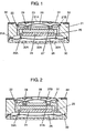
- FIG. 1 is a sectional view showing a loudspeaker according to an embodiment of the present invention.
- Hollow cylindrical frame 21 is formed by resin molding.
- Yoke 22 has a U-shaped cross section and is made of iron that is a magnetic metal.
- An outer wall portion of yoke 22 is integrated with frame 21 by insert molding and supported by an inner wall of frame 21.
- Columnar magnet 23 having a first pole and a second pole (north pole and south pole) at lower and upper sides is provided inside yoke 22 with the second pole attached to a center of a top surface of yoke 22.
- Plate 24 is also made of a magnetic material and is attached to the lower surface, that is, the first pole of magnet 23. Both poles of magnet 23 face first opening 21A and second opening 21B of frame 21, respectively.
- First diaphragm 26 is attached to first opening 21A of frame 21 at its outer periphery. To the end part, a second end of first voice coil 26A is attached, while a first end thereof is located in magnetic gap 25.
- Yoke 22 forms magnetic flux flow between the both poles of magnet 23.
- Groove portion 27 is provided on a surface facing second opening 21B of yoke 22, and second diaphragm 28 is attached to second opening 21B facing first opening 21A of frame 21 at its outer periphery. To an end of second diaphragm 28, a second end of second voice coil 29 is attached, while first end of second voice coil 29 is located in groove portion 27.
- groove portion 27 has a width and a depth appropriately set to generate magnetic saturation by suitably narrowing a magnetic path of yoke 22 that forms a magnetic circuit, and to function as a second magnetic gap. Accordingly, magnetic flux leaking into groove portion 27 that is the second magnetic gap is increased, and an output of sound pressure of the loudspeaker is increased.
- magnet 23, plate 24, magnetic gap 25, voice coil 26A, yoke 22, and diaphragm 26 form a first loudspeaker part. Furthermore, magnet 23, plate 24, groove portion 27, voice coil 29, yoke 22, and diaphragm 28 form a second loudspeaker part.
- First protector 30 provided with a plurality of holes 30A for releasing sound and second protector 31 provided with center hole 31A are respectively attached to first and second openings 21A and 21B of frame 21 such that they cover diaphragm 26 and 28, respectively.
- Terminal boards 32 are provided at four portions of frame 21 and electrically connected (not shown) to both ends of first voice coil 26A and second voice coil 29, respectively.
- Ring-shaped groove portion 27 can be formed extremely easily by casting at the same time yoke 22 is formed. Furthermore, groove portion 27 can be extremely easily formed by forging of sheet-like or hoop-shaped iron material before, after or when yoke 22 is formed. In this way, since groove portion 27 is formed by casting or forging and used as the second magnetic gap, the second magnetic gap can be finished to have a certain shape and size with high accuracy when yoke 22 is formed. Therefore, when the loudspeaker is incorporated, no error in incorporating the magnetic gap occurs.
- groove portion 27 provided in yoke 22 functions as the second magnetic gap into which second voice coil 29 is inserted, and two loudspeakers are included.
- FIG. 2 is a side sectional view showing a modification of the above-mentioned configuration.
- This configuration is different from the configuration shown in FIG. 1 in groove portion 27A.
- This configuration includes standing wall (hereinafter, which is referred to as "wall”) 27B formed by extending both side walls of groove portion 27A upwardly.
- wall 27B By providing wall 27B, the depth of groove portion 27A is increased, as well as leakage flux is more concentrated to improve the magnetic efficiency, and the output of sound pressure of the loudspeaker is increased to improve the sound pressure frequency property.
- wall 27B is provided on both sides of groove portion 27A, but it may be provided on only one side if necessary.
- wall 27B can be formed extremely easily by using a casting mold, and when yoke 22 is formed by forging, wall 27B can be formed extremely easily as a buildup portion when groove portion 27A is formed at the time of forging.
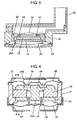
- FIG. 3 is also a side sectional view showing a modification of the configuration shown in FIG. 1.
- This configuration is different from the configuration shown in FIG. 1 in that instead of protector 31, port 33 is provided. With port 33, it is possible to release sound from a certain position of equipment into which this loudspeaker is incorporated.
- FIG. 4 is a side sectional view showing a loudspeaker having another configuration according to an embodiment of the present invention.
- FIGs. 1 to 3 show configurations of an internal magnetic type loudspeaker having columnar magnet 23 in a center part thereof. Meanwhile, this configuration shows an external magnetic type loudspeaker using ring-shaped magnet 43.
- Frame 41 made of resin has first and second openings 41A and 41B at lower and upper ends and is formed as a hollow frame.
- Ring-shaped plate 42 is made of a magnetic material and integrated with frame 41 by insert molding.
- Ring-shaped magnet 43 is attached to plate 42 at its first pole. Both plate 42 and magnet 43 are provided inside frame 41. Both poles of magnet 43 face first opening 41A and second opening 41B of frame 41, respectively.
- Yoke 44 made of a magnetic material is attached to a second pole of magnet 43 and has center pole 44A located in a through hole in a center portion of ring-shaped magnet 43 and plate 42. Yoke 44 forms magnetic flux flow between the first pole and the second pole of magnet 43.
- First diaphragm 45 is attached at its outer circumference such that it covers first opening 41A.
- a first end of first voice coil 47 is located in magnetic gap 46 between center pole 44A and an inner circumference of plate 42, and a second end thereof is attached to first diaphragm 45.
- Second diaphragm 48 is attached at its outer circumference such that it covers the second opening 41B.
- a first end of second voice coil 49 is located in groove portion 44B provided in yoke 44 in an annular shape, and a second end thereof is attached to second diaphragm 48.
- Protectors 50 and 51 are attached to first and second openings 41A and 41B such that they cover diaphragms 45 and 48, respectively.
- magnet 43, plate 42, magnetic gap 46, voice coil 47, yoke 44 and diaphragm 45 form a first loudspeaker part. Furthermore, plate 42, magnet 43, groove portion 44B, voice coil 49, yoke 44 and diaphragm 49 form a second loudspeaker part.
- groove portion 44B can be formed by casting or forging when yoke 44 is formed. As in FIG. 2, groove portion 44B may be provided with a standing wall.
- groove portion 44B provided in yoke 44 functions as a second magnetic gap for the second loudspeaker part, and second voice coil 49 is inserted therein. Therefore, when yoke 44 is formed, the magnetic gap can be finished to have a certain shape and size with high accuracy. Accordingly, when the loudspeaker is incorporated, no error in incorporating the magnetic gap occurs.
- plate 42 is integrated with frame 41 by insert molding.
- an outer wall portion of yoke 44 may be integrated with frame 41 by insert molding.
- the relation between frame 41 and groove portion 44B provided in yoke 44 is determined by accuracy of a mold. Therefore, the location accuracy of the magnetic gap is more improved and the quality of the loudspeaker is stabilized.
- a magnetic material having high magnetic permeability and low coercive force is used for yokes 22 and 44 and plates 24 and 42.
- a magnetic material having high magnetic permeability and low coercive force is used for example, iron is preferably used.
- magnets 23 and 43 a magnet material having a large energy product is used. Ferrite magnets, samarium-cobalt magnets, neodymium base magnets, and the like are preferred. Neodymium base magnets are preferably used because they have a high energy product and are suitable for achieving small size and light weight. If necessary, magnetic materials and magnet materials may be subjected to an anti-rust treatment.
- Frames 21 and 41 are formed by using a resin material.
- resin material thermoplastic resin that does not need hardening treatment is preferred.
- ABS, PBT, etc. are used.
- thermoplastic resin having a glass-transition temperature of 100°C or more An example thereof may include polyamide (PA) that is nylon resin containing glass, which has high heat resistance property and high rigidity.
- PA polyamide
- a resin material is required to have an excellent fluidity inside a mold. In order to improve fluidity, various additives may be used.
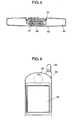
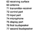
- FIG. 5 is a sectional view of a mobile telephone seen from the upper side.
- FIG. 6 is a front view showing only a display part at the upper side of the mobile telephone shown in FIG. 5.
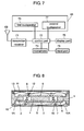
- FIG. 7 is a block diagram showing a configuration of the mobile telephone shown in FIG. 5.
- input part 73 receives a telephone number that is information about destination of the call from a user or an originating operation based on search for an installed telephone directory.
- Control part 72 transmits radio wave including an originating signal from transmitter-receiver 71 to the outside by using antenna 63 based on the signal from input part 73.
- Microphone 74 inputs a sound from a user and transmits it to control part 72.
- Control part 72 transmits a signal including sound data from transmitter-receiver 71 to the outside by using antenna 63.
- Display part 75 displays a telephone number input from input part 73 by a user or search content of telephone directory.
- transmitter-receiver 71 When a call is incoming, transmitter-receiver 71 that receives incoming signal via antenna 63 transmits the signal to control part 72. Control part 72 releases ringtone by first diaphragm 26 of first loudspeaker part 76. At the same time, incoming number etc. may be displayed on display part 75. Input part 73 receives incoming operation by a user and control part 72 transmits a signal of incoming operation from transmitter-receiver 71. Thus, the communication line is connected. Note here that in a case where transmitter-receiver 71 transmits/receives a digital signal, control part 72 functions also as an encoder and a decoder:
- second diaphragm 28 of second loudspeaker part 77 is provided at the side of display surface (receiving surface) 62.
- second diaphragm 28 is used as a receiving loudspeaker that does not require a large sound pressure output as a loudspeaker using leakage flux in groove portion 27.
- location accuracy of the magnetic gap is improved. Therefore, incorporating error is suppressed, and variation in sound pressure output is suppressed.
- Equipment having small variation, for listener, in quality of sound pressure output by the mounted loudspeaker is provided.
- the reduction of magnets to be used contributes to lightening the weight of the equipment.
- loudspeakers shown in FIGs. 2 and 4 may be used.
- second diaphragm 48 is provided at the side of display surface 62.
- a loudspeaker has a columnar shape.
- a loudspeaker may be formed to have an appearance of a rectangular parallelepiped, or an oval, or an elliptical shape.
- An inside magnetic circuit may be formed in an oval or an elliptical shape other than a circular shape if necessary.
- the groove portion is not limited to a circular shape and it may be changed to an oval, or an elliptical, a racetrack shape, etc. in accordance with the shape of the magnetic circuit.
- a groove portion provided in a yoke is used as a magnetic gap. Consequently, incorporating error occurring when a loudspeaker is incorporated is suppressed and variation is eliminated, and thus a loudspeaker with stable quality can be achieved.
Landscapes
- Engineering & Computer Science (AREA)
- Physics & Mathematics (AREA)
- Acoustics & Sound (AREA)
- Signal Processing (AREA)
- Manufacturing & Machinery (AREA)
- Audible-Bandwidth Dynamoelectric Transducers Other Than Pickups (AREA)
- Details Of Audible-Bandwidth Transducers (AREA)
Applications Claiming Priority (2)
| Application Number | Priority Date | Filing Date | Title |
|---|---|---|---|
| JP2003162048A JP4111067B2 (ja) | 2003-06-06 | 2003-06-06 | スピーカおよびこれを用いた携帯電話装置 |
| PCT/JP2004/007662 WO2004110097A1 (ja) | 2003-06-06 | 2004-05-27 | スピーカとその製造方法、それを用いた携帯電話 |
Publications (2)
| Publication Number | Publication Date |
|---|---|
| EP1633167A1 true EP1633167A1 (de) | 2006-03-08 |
| EP1633167A4 EP1633167A4 (de) | 2009-11-04 |
Family
ID=33508653
Family Applications (1)
| Application Number | Title | Priority Date | Filing Date |
|---|---|---|---|
| EP04735116A Withdrawn EP1633167A4 (de) | 2003-06-06 | 2004-05-27 | Lautsprecher, herstellungsverfahren daf r und mobiltelefon damit |
Country Status (7)
| Country | Link |
|---|---|
| US (1) | US7519191B2 (de) |
| EP (1) | EP1633167A4 (de) |
| JP (1) | JP4111067B2 (de) |
| KR (1) | KR100663118B1 (de) |
| CN (1) | CN1698399B (de) |
| TW (1) | TW200503575A (de) |
| WO (1) | WO2004110097A1 (de) |
Cited By (2)
| Publication number | Priority date | Publication date | Assignee | Title |
|---|---|---|---|---|
| GB2461929A (en) * | 2008-07-17 | 2010-01-20 | Strong Pacific | Earphones with compound drive units and level control |
| US9532145B2 (en) | 2010-12-23 | 2016-12-27 | Eagle Acoustics Manufacturing, Llc | Low-profile speaker |
Families Citing this family (25)
| Publication number | Priority date | Publication date | Assignee | Title |
|---|---|---|---|---|
| JP2006191213A (ja) * | 2004-12-28 | 2006-07-20 | Citizen Electronics Co Ltd | 電気音響変換器及び携帯端末装置 |
| EP1686834A1 (de) * | 2005-01-28 | 2006-08-02 | Sonion Horsens A/S | Miniature-Mehrfachlautsprechermodul |
| KR100661921B1 (ko) | 2005-04-15 | 2006-12-27 | 삼성전기주식회사 | 진동 및 음향 발생장치와 이에 사용되는 요크 |
| EP1956866A4 (de) * | 2006-03-13 | 2010-08-04 | Panasonic Corp | Composite lautsprecher und sein herstellungsverfahren |
| KR100785077B1 (ko) | 2006-07-24 | 2007-12-12 | 부산대학교 산학협력단 | 마이크로 스피커 |
| US8385568B2 (en) * | 2010-01-06 | 2013-02-26 | Apple Inc. | Low-profile speaker arrangements for compact electronic devices |
| CN201839425U (zh) * | 2010-04-27 | 2011-05-18 | 常州美欧电子有限公司 | 双回路集成发声器件 |
| JP2012124719A (ja) * | 2010-12-08 | 2012-06-28 | Alpine Electronics Inc | 複合スピーカ |
| EP2521375B1 (de) * | 2011-05-03 | 2014-04-16 | Knowles Electronics Asia PTE. Ltd. | Lautsprecher mit einer einen Teilchenfilter enthaltenden Öffnung |
| CN202190382U (zh) * | 2011-07-04 | 2012-04-11 | 常州美欧电子有限公司 | 发声器件 |
| US8831270B1 (en) * | 2013-08-08 | 2014-09-09 | Dimitar Kirilov Dimitrov | Single magnet coaxial loudspeaker |
| CN203912181U (zh) * | 2014-04-30 | 2014-10-29 | 瑞声光电科技(常州)有限公司 | 扬声器 |
| WO2016170595A1 (ja) * | 2015-04-21 | 2016-10-27 | 賢太 田中 | 電気音響変換装置 |
| ITUA20163268A1 (it) * | 2015-05-22 | 2017-11-09 | Ask Ind Spa | Gruppo trasduttore elettro-acustico inerziale. |
| CN108574918A (zh) * | 2018-07-19 | 2018-09-25 | 陈新得 | 一种两分频双磁路扬声器 |
| CN109040921B (zh) * | 2018-07-26 | 2022-02-22 | 维沃移动通信有限公司 | 一种发声结构及终端 |
| CN108966089A (zh) * | 2018-10-09 | 2018-12-07 | 安庆市汇智科技咨询服务有限公司 | 一种扬声器 |
| US11044562B1 (en) * | 2020-01-21 | 2021-06-22 | Resonado, Inc. | Multi-diaphragm speaker driven by multiple voice coil plates and a shared permanent magnet pair |
| GB2591223A (en) * | 2020-01-22 | 2021-07-28 | Gp Acoustics International Ltd | Loudspeakers |
| CN111343549B (zh) * | 2020-03-05 | 2021-02-19 | 瑞声科技(新加坡)有限公司 | 扬声器箱 |
| CN111641907B (zh) * | 2020-06-24 | 2021-07-09 | 瑞声科技(新加坡)有限公司 | 发声器件 |
| EP4287650A1 (de) * | 2021-02-01 | 2023-12-06 | Samsung Electronics Co., Ltd. | Lautsprecher mit verbesserten bl-eigenschaften und elektronische vorrichtung damit |
| WO2023060009A2 (en) * | 2021-10-07 | 2023-04-13 | Sonos, Inc. | Speaker device |
| CN114390407A (zh) * | 2022-01-25 | 2022-04-22 | 瑞声光电科技(常州)有限公司 | 同轴扬声器 |
| CN216960175U (zh) * | 2022-01-25 | 2022-07-12 | 瑞声光电科技(常州)有限公司 | 一种同轴扬声器 |
Citations (3)
| Publication number | Priority date | Publication date | Assignee | Title |
|---|---|---|---|---|
| EP0650308A1 (de) * | 1993-10-25 | 1995-04-26 | Star Micronics Co., Ltd. | Elektroakustischer Wandler und dessen Herstellungsmethode |
| EP1257147A2 (de) * | 2001-05-08 | 2002-11-13 | Matsushita Electric Industrial Co., Ltd. | Lautsprecher und Mobilendgerät |
| JP2003032792A (ja) * | 2001-07-11 | 2003-01-31 | Nec Tokin Corp | マルチモードデバイス |
Family Cites Families (6)
| Publication number | Priority date | Publication date | Assignee | Title |
|---|---|---|---|---|
| JP3521830B2 (ja) * | 2000-02-14 | 2004-04-26 | ミネベア株式会社 | 携帯用通信装置における報知装置 |
| JP2001300422A (ja) * | 2000-04-21 | 2001-10-30 | Citizen Electronics Co Ltd | 多機能変換器とその駆動方法 |
| KR100369853B1 (ko) | 2001-01-09 | 2003-01-30 | 주식회사 이엠텍 | 휴대용 통신기기의 양방향 통합형 스피커-리시버 |
| JP3935393B2 (ja) | 2001-05-08 | 2007-06-20 | 松下電器産業株式会社 | スピーカおよび携帯端末装置 |
| JP2002335597A (ja) * | 2001-05-09 | 2002-11-22 | Citizen Electronics Co Ltd | 複合スピーカー |
| JP3927782B2 (ja) * | 2001-09-19 | 2007-06-13 | ホシデン株式会社 | 電気音響変換装置 |
-
2003
- 2003-06-06 JP JP2003162048A patent/JP4111067B2/ja not_active Expired - Fee Related
-
2004
- 2004-05-19 TW TW093114079A patent/TW200503575A/zh unknown
- 2004-05-27 US US10/522,943 patent/US7519191B2/en not_active Expired - Fee Related
- 2004-05-27 CN CN2004800005692A patent/CN1698399B/zh not_active Expired - Fee Related
- 2004-05-27 WO PCT/JP2004/007662 patent/WO2004110097A1/ja active Application Filing
- 2004-05-27 EP EP04735116A patent/EP1633167A4/de not_active Withdrawn
- 2004-05-27 KR KR1020057000747A patent/KR100663118B1/ko not_active IP Right Cessation
Patent Citations (3)
| Publication number | Priority date | Publication date | Assignee | Title |
|---|---|---|---|---|
| EP0650308A1 (de) * | 1993-10-25 | 1995-04-26 | Star Micronics Co., Ltd. | Elektroakustischer Wandler und dessen Herstellungsmethode |
| EP1257147A2 (de) * | 2001-05-08 | 2002-11-13 | Matsushita Electric Industrial Co., Ltd. | Lautsprecher und Mobilendgerät |
| JP2003032792A (ja) * | 2001-07-11 | 2003-01-31 | Nec Tokin Corp | マルチモードデバイス |
Non-Patent Citations (1)
| Title |
|---|
| See also references of WO2004110097A1 * |
Cited By (2)
| Publication number | Priority date | Publication date | Assignee | Title |
|---|---|---|---|---|
| GB2461929A (en) * | 2008-07-17 | 2010-01-20 | Strong Pacific | Earphones with compound drive units and level control |
| US9532145B2 (en) | 2010-12-23 | 2016-12-27 | Eagle Acoustics Manufacturing, Llc | Low-profile speaker |
Also Published As
| Publication number | Publication date |
|---|---|
| JP4111067B2 (ja) | 2008-07-02 |
| TW200503575A (en) | 2005-01-16 |
| KR20050052454A (ko) | 2005-06-02 |
| US7519191B2 (en) | 2009-04-14 |
| KR100663118B1 (ko) | 2007-01-02 |
| CN1698399B (zh) | 2011-06-22 |
| US20060120551A1 (en) | 2006-06-08 |
| CN1698399A (zh) | 2005-11-16 |
| WO2004110097A1 (ja) | 2004-12-16 |
| JP2004364101A (ja) | 2004-12-24 |
| EP1633167A4 (de) | 2009-11-04 |
Similar Documents
| Publication | Publication Date | Title |
|---|---|---|
| US7519191B2 (en) | Loudspeaker, manufacturing method thereof, and mobile telephone using the same | |
| US20090136065A1 (en) | Composite speaker and its manufacturing method | |
| KR100662533B1 (ko) | 스피커 | |
| EP1942701B1 (de) | Lautsprecher | |
| EP2356822B1 (de) | Elektronische geräte samt auf einer basisplatte angeordneten akustischen aktuatoren sowie verwandte verfahren und mobilfunktelefone | |
| CN210725317U (zh) | 矩形的微型扬声器及音响设备 | |
| US8301188B2 (en) | Electronic devices including substrate mounted acoustic actuators and related methods and mobile radiotelephones | |
| US20120213398A1 (en) | Speaker, and electronic apparatus and cellular phone using the speaker | |
| KR20030033695A (ko) | 휴대용 단말기의 양방향 스피커 | |
| CN213342569U (zh) | 扬声器箱及移动终端 | |
| JP4557495B2 (ja) | 電気音響変換器 | |
| KR20020003169A (ko) | 휴대용 통신 단말기의 수신 유니트 | |
| KR101610231B1 (ko) | 외자형 스피커 어셈블리 | |
| KR100375125B1 (ko) | 통신 단말기의 수신 유니트 | |
| CN213342571U (zh) | 扬声器箱及移动终端 | |
| US7151840B2 (en) | Magnet system of a sound transducer | |
| KR100534154B1 (ko) | 통신 단말기용 마이크로 스피커의 내부결합구조 | |
| KR100401000B1 (ko) | 리시버가 결합된 스피커 | |
| JP2007243870A (ja) | スピーカ | |
| JP2006166151A (ja) | ステレオ用スピーカ | |
| KR20030083774A (ko) | 자화필름을 이용한 고정형 코일구조를 갖는 단방향/양방향전기-음향 변환기 및 전기-음향 변환 방법 | |
| KR20060023329A (ko) | 자기장 누설 방지 구조를 갖는 소형스피커 | |
| KR20040091277A (ko) | 다기능 전자음향 변환기의 요크 구조 | |
| KR200295324Y1 (ko) | 이종 결합형 스피커 | |
| JP2003333686A (ja) | スピーカ |
Legal Events
| Date | Code | Title | Description |
|---|---|---|---|
| PUAI | Public reference made under article 153(3) epc to a published international application that has entered the european phase |
Free format text: ORIGINAL CODE: 0009012 |
|
| 17P | Request for examination filed |
Effective date: 20050126 |
|
| AK | Designated contracting states |
Kind code of ref document: A1 Designated state(s): AT BE BG CH CY CZ DE DK EE ES FI FR GB GR HU IE IT LI LU MC NL PL PT RO SE SI SK TR |
|
| DAX | Request for extension of the european patent (deleted) | ||
| RAP1 | Party data changed (applicant data changed or rights of an application transferred) |
Owner name: PANASONIC CORPORATION |
|
| A4 | Supplementary search report drawn up and despatched |
Effective date: 20091005 |
|
| STAA | Information on the status of an ep patent application or granted ep patent |
Free format text: STATUS: THE APPLICATION HAS BEEN WITHDRAWN |
|
| 18W | Application withdrawn |
Effective date: 20110201 |