EP1632985A1 - high-pressure discharge lampe - Google Patents
high-pressure discharge lampe Download PDFInfo
- Publication number
- EP1632985A1 EP1632985A1 EP05017122A EP05017122A EP1632985A1 EP 1632985 A1 EP1632985 A1 EP 1632985A1 EP 05017122 A EP05017122 A EP 05017122A EP 05017122 A EP05017122 A EP 05017122A EP 1632985 A1 EP1632985 A1 EP 1632985A1
- Authority
- EP
- European Patent Office
- Prior art keywords
- coating
- discharge
- discharge vessel
- pressure discharge
- discharge lamp
- Prior art date
- Legal status (The legal status is an assumption and is not a legal conclusion. Google has not performed a legal analysis and makes no representation as to the accuracy of the status listed.)
- Granted
Links
Images

Classifications
-
- H—ELECTRICITY
- H01—ELECTRIC ELEMENTS
- H01J—ELECTRIC DISCHARGE TUBES OR DISCHARGE LAMPS
- H01J61/00—Gas-discharge or vapour-discharge lamps
- H01J61/02—Details
- H01J61/04—Electrodes; Screens; Shields
- H01J61/06—Main electrodes
- H01J61/073—Main electrodes for high-pressure discharge lamps
-
- H—ELECTRICITY
- H01—ELECTRIC ELEMENTS
- H01J—ELECTRIC DISCHARGE TUBES OR DISCHARGE LAMPS
- H01J61/00—Gas-discharge or vapour-discharge lamps
- H01J61/02—Details
- H01J61/54—Igniting arrangements, e.g. promoting ionisation for starting
- H01J61/547—Igniting arrangements, e.g. promoting ionisation for starting using an auxiliary electrode outside the vessel
-
- H—ELECTRICITY
- H01—ELECTRIC ELEMENTS
- H01J—ELECTRIC DISCHARGE TUBES OR DISCHARGE LAMPS
- H01J61/00—Gas-discharge or vapour-discharge lamps
- H01J61/02—Details
- H01J61/30—Vessels; Containers
- H01J61/35—Vessels; Containers provided with coatings on the walls thereof; Selection of materials for the coatings
Definitions
- the invention relates to a high-pressure discharge lamp according to the preamble of patent claim 1.
- Such a high-pressure discharge lamp is disclosed, for example, in European patent EP 0 991 107 B1.
- EP 0 991 107 B1 On page 4, in lines 12 to 26 of column 6 of this patent a unilaterally capped high-pressure discharge lamp for a motor vehicle headlight is described which has a surrounded by a glass outer bulb discharge vessel, wherein the outer bulb is provided with a transparent, electrically conductive layer which extends over the entire discharge space of the lamp. This layer is connected to the circuit-internal ground reference potential of the operating device of the high-pressure discharge lamp in order to improve the electromagnetic compatibility of the lamp.
- the high-pressure discharge lamp according to the invention has a light-permeable discharge vessel, an ionizable filling arranged in the discharge space of the discharge vessel and extending into the discharge space of the discharge vessel Electrodes for generating a gas discharge, as well as led out of the discharge vessel power supply to the power supply of the electrodes, wherein the surface of the discharge vessel is at least partially provided with a translucent, electrically conductive coating, so that between the coating and at least one electrode and / or power supply, a capacitive coupling consists.
- the abovementioned coating, together with the at least one electrode and optionally with the associated power supply, forms a capacitor, the quartz glass of the discharge vessel and the filling gas in the discharge space forming the dielectric of this capacitor.
- a dielectrically impeded discharge is generated in the discharge space between the at least one electrode and the coating.
- This dielectrically impeded discharge generates a sufficient number of free charge carriers in the discharge space in order to enable the electrical breakdown between the two electrodes of the high-pressure discharge lamp or to significantly reduce the ignition voltage required for this purpose.
- the invention is therefore particularly suitable for mercury-free metal halide high-pressure discharge lamps, which have an increased ignition voltage due to the lack of mercury.
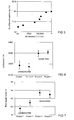
- FIG. 5 shows the dependence of the breakdown voltage of the discharge gap on the resistance of the partial coating according to the invention for a plurality of mercury-free metal halide high-pressure discharge lamps with a rated power of 35 watt, which are provided with a different thickness partial coating shown.
- the resistance of the coating in the unit ohms / cm is plotted on a logarithmic scale and on the vertical axis the breakdown voltage of the discharge path of the lamp in kilovolts. The resistance was measured between two points of the coating, which were arranged at a distance of 1 cm.
- the breakdown voltage for lamps of this type whose partial coating has a resistance per unit length of less than or equal to 10 5 ohm / cm, the discharge path has a significantly reduced breakdown voltage.
- the thickness of the partial according to the invention Coating is therefore chosen so that its resistance per unit length is in the order of magnitude of 10 3 ohms / cm to 10 5 ohms / cm. With a resistance per unit length below 10 3 ohm / cm, the layer thickness is so large that it can adversely affect the optical properties of the headlamp system due to light reflection.
- the layer thickness is selected such that its resistance per unit length is in the order of 10 4 ohms / cm.
- the breakdown voltage of the discharge gap has been reduced in this case from 20 kV in uncoated lamps to about 17.5 kV.
- the coating according to the invention therefore correspondingly reduces the required ignition voltage.
- the translucent, electrically conductive coating is advantageously applied to the outer surface of the discharge vessel, since it is not exposed to the chemical attack of the metal halides and the discharge plasma there.
- the abovementioned coating is arranged at least in the region of the discharge space and extends over a part of the circumference of the discharge space in order to ensure a good capacitive coupling of the coating to at least one electrode and preferably even to both electrodes by the planar expansion of the coating.
- the light-transmitting, electrically conductive partial coating is formed such that it extends as far as the at least one molybdenum foil and one of the two sides the molybdenum foil faces the coating.
- the molybdenum foil and the coating form a type of plate capacitor, wherein the material of the discharge vessel, preferably quartz glass, arranged therebetween forms the dielectric of this capacitor.
- the light-transmitting, electrically conductive coating is advantageously on one Restricted below the electrodes arranged surface region of the discharge vessel.
- the coating reflects a portion of the infrared radiation generated by the discharge back into the discharge space and thus provides for selective heating of the colder, lying below the electrodes areas of the discharge vessel in which collect the metal halides used for the light generation.
- the efficiency of the lamp can be increased without also heating the hot regions of the discharge vessel lying above the electrodes.
- the application of the coating only on the colder underside of the discharge vessel reduces the thermal load of the coating, so that correspondingly lower demands can be placed on the thermal resistance of the coating materials.
- the lamps according to the invention of groups 3 and 4 have a further advantage over the uncoated lamps of groups 1 and 2.
- the lamps according to the invention of groups 3 and 4 have a higher burning voltage than the uncoated lamps of the groups 1 and 2.
- a correspondingly lower lamp current is required in the lamps according to the invention during lamp operation to achieve the desired rated power of 35 watts. Accordingly, the operating devices can be dimensioned for lower currents.
- the high-pressure discharge lamp is designed as a single-ended high-pressure discharge lamp whose discharge vessel has a socket-sealed end and a socket-sealed end from each of which a lead-out led out for the electrodes, wherein led out of the sockelfemen end power supply with a connected to the socket recycled current return.
- the translucent, electrically conductive coating on the basis of the above explanations and because this lamp is operated in a horizontal position with current recirculation running below the electrodes, is arranged on a surface region of the discharge vessel facing the current return.
- the abovementioned coating is preferably limited to a surface region of the discharge vessel which is arranged between the current return and the connection axis of the electrodes and extends in the longitudinal direction of the lamp over at least part of the discharge space and a part of one of the two ends of the discharge vessel.
- the surface region of the discharge vessel facing the current return plays only a minor role in the use of the high-pressure discharge lamp in a vehicle headlight for generating the desired light distribution. Therefore, even a slight absorption of light caused by the coating is meaningless.
- the high-pressure discharge lamp according to the invention is advantageously provided with a light-permeable outer bulb which encloses at least the discharge space of the discharge vessel.
- the glass of the outer envelope is doped with ultraviolet radiation absorbing agents to absorb the UV radiation emitted by the gas discharge.
- the space between the outer bulb and the discharge vessel is advantageously provided with a gas filling having a cold filling pressure in the range of 5 kPa to 150 kPa.
- Cold filling pressure here means the filling pressure measured at a gas filling temperature of 22 degrees Celsius.
- the gas filling removes gaseous contaminants such as water vapor and carbon dioxide and combustion gases formed during the lamp vessel sealing, and reduces the temperature gradient along the discharge vessel.
- the abovementioned gas filling advantageously contains inert gases which do not undergo any chemical reaction with the material of the coating according to the invention on the discharge vessel.
- the gas filling therefore preferably contains nitrogen or at least one noble gas.
- the gas filling advantageously contains small amounts of oxygen in order to counteract a diffusion of oxygen from the coating, which is preferably in the form of a doped tin oxide layer or ITO layer, on the discharge vessel.
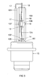
- the preferred exemplary embodiment of the invention shown schematically in FIG. 3 is a mercury-free metal halide high-pressure discharge lamp with an electrical power consumption of approximately 35 watts.
- This lamp is intended for use in a vehicle headlight. It has a two-sided sealed discharge vessel 30 made of quartz glass with a volume of 24 mm 3 , in which an ionizable filling, consisting of xenon and halides of the metals sodium, scandium, zinc and indium, gas-tight enclosed.
- the inner contour of the discharge vessel 10 is circular-cylindrical and its outer contour is ellipsoidal.
- the inner diameter of the discharge space 106 is 2.6 mm and its outer diameter is 6.3 mm.
- the two ends 101, 102 of the discharge vessel 10 are each sealed by means of a molybdenum foil sealing 103, 104.
- the electrodes 11, 12 are made of tungsten. Their thickness or their diameter is 0.30 mm. The distance between the electrodes 11, 12 is 4.2 mm.
- the electrodes 11, 12 are in each case electrically conductively connected to one of the molybdenum foil melts 103, 104 and via the base-remote power supply wire 13 and the current return 17 or via the socket-side power supply wire 14 to an electrical connection of the lamp base 15, which consists essentially of plastic.
- the discharge vessel 10 is enveloped by a glass outer bulb 16.
- the outer bulb 16 has an extension 161 anchored in the base 15.
- the discharge vessel 10 has a tubular extension 105 made of quartz glass on the base side, in which the socket-side power supply 14 extends:
- the surface region of the discharge vessel 10 facing the current return 17 is provided with a transparent, electrically conductive coating 107.
- This coating 107 extends in the longitudinal direction of the lamp over the entire length of the discharge space 106 and over a part, about 50 percent, of the length of the sealed ends 101, 102 of the discharge vessel 10.
- the coating 107 is mounted on the outside of the discharge vessel 10 and extends over about 5 percent to 10 percent of the circumference of the discharge vessel 10.
- FIGS. 1 and 2 show two different views of the discharge vessel 10 and the coating 107 of the high-pressure discharge lamp depicted in FIG.
- the coating 107 covers both ends 101, 102 of the discharge vessel 10 in a symmetrical manner.
- the coating 107 consists of doped tin oxide, for example of tin oxide doped with fluorine or antimony or, for example, boron and / or lithium-doped tin oxide.
- This high-pressure discharge lamp is operated in a horizontal position, that is, with arranged in a horizontal plane electrodes 11, 12, wherein the lamp is oriented such that the current return path 17 extends below the discharge vessel 30 and the outer bulb 16.
- the space between the outer bulb 16 and the discharge vessel 10 is filled with an inert gas having a cold filling pressure in the range of 5 kPa to 150 kPa.
- the inert gas is mixed with small amounts of oxygen.
- the amount of oxygen is adjusted so that, on the one hand, diffusion of oxygen from the tin oxide layer 107 is prevented and, on the other hand, no oxidation of the dopants in the tin oxide coating 107 is caused.
- the inert gas is preferably nitrogen or a noble gas or a noble gas mixture or a nitrogen-noble gas mixture.
- FIG. 4 shows the discharge vessel 10 of the high-pressure discharge lamp depicted in FIG. 3 with an alternative coating 107 '.
- the coating 107 ' differs from the above-described coating 107 only in that the coating 107' extends in the longitudinal direction of the lamp only over the length of the discharge space 106 and about 50 percent of the length of the socket-proximal end 101 of the discharge vessel 10.
- the coating 107 can also consist of another light-transmitting, electrically conductive material.
- it may be formed as a so-called ITO layer, that is, an indium tin oxide layer.
- the ITO layer may comprise, for example, 90 weight percent indium oxide and 10 weight percent tin oxide.
- the coating 107 or 107 ' can be electrically coupled, for example by suitable means, to an ignition device in order to apply to the high-pressure discharge lamp via the coating 107, 107' voltage pulses for igniting the gas discharge in the discharge space 106.
- the coating 107 or 107 ' may extend over the entire surface of the discharge vessel 10. But it is also possible that the coating 107 or 107 'extends in the region of the discharge space 106, for example, only over half or a third of the circumference of the discharge vessel 10. In the region of the ends 101, 102 of the discharge vessel 10, the coating 107 or 107 'may extend, for example, over the entire circumference of the discharge vessel 10 or even over a third, half or other fraction of the discharge vessel circumference.
- the coating 107 or 107 ' is preferably designed such that it serves as an ignition aid and for heating the coldest point of the discharge vessel, the so-called cold spot.
- the electrical resistance of the translucent coating 107 or 107 ' is in the range of 40,000 ohms to 200,000 ohms.
Abstract
Description
Die Erfindung betrifft eine Hochdruckentladungslampe gemäß des Oberbegriffs des Patentanspruchs 1.The invention relates to a high-pressure discharge lamp according to the preamble of
Eine derartige Hochdruckentladungslampe ist beispielsweise in der europäischen Patentschrift EP 0 991 107 B1 offenbart. Auf Seite 4, in den Zeilen 12 bis 26 der Spalte 6 dieser Patentschrift ist eine einseitig gesockelte Hochdruckentladungslampe für einen Kraftfahrzeugscheinwerfer beschrieben, die ein von einem gläsernen Außenkolben umgebenes Entladungsgefäß besitzt, wobei der Außenkolben mit einer lichtdurchlässigen, elektrisch leitfähigen Schicht versehen ist, die sich über den gesamten Entladungsraum der Lampe der erstreckt. Diese Schicht ist mit dem schaltungsinternen Massebezugspotential des Betriebsgerätes der Hochdruckentladungslampe verbunden, um die elektromagnetische Verträglichkeit der Lampe zu verbessern.Such a high-pressure discharge lamp is disclosed, for example, in European patent EP 0 991 107 B1. On
Es ist die Aufgabe der Erfindung, eine Hochdruckentladungslampe, insbesondere eine quecksilberfreie Halogen-Metalldampf-Hochdruckentladungslampe für Fahrzeugscheinwerfer mit verbesserter Zündwilligkeit bereitzustellen.It is the object of the invention to provide a high-pressure discharge lamp, in particular a mercury-free metal halide high-pressure discharge lamp for vehicle headlights with improved ignitability.
Diese Aufgabe wird erfindungsgemäß durch die Merkmale des Patentanspruchs 1 gelöst. Besonders vorteilhafte Ausführungen der Erfindung sind in den abhängigen Patentansprüchen beschrieben.This object is achieved by the features of
Die erfindungsgemäße Hochdruckentladungslampe besitzt ein lichtdurchlässiges Entladungsgefäß, eine im Entladungsraum des Entladungsgefäßes angeordnete ionisierbare Füllung und sich in den Entladungsraum des Entladungsgefäßes erstreckende Elektroden zum Erzeugen einer Gasentladung, sowie aus dem Entladungsgefäß herausgeführte Stromzuführungen zur Energieversorgung der Elektroden, wobei die Oberfläche des Entladungsgefäßes zumindest partiell mit einer lichtdurchlässigen, elektrisch leitfähigen Beschichtung versehen ist, so dass zwischen der Beschichtung und mindestens einer Elektrode oder / und Stromzuführung eine kapazitive Kopplung besteht. Die vorgenannte Beschichtung bildet zusammen mit der mindestens einen Elektrode und gegebenenfalls mit der dazugehörenden Stromzuführung einen Kondensator, wobei das dazwischen liegende Quarzglas des Entladungsgefäßes und das Füllgas im Entladungsraum das Dielektrikum dieses Kondensators bilden. Dadurch wird, insbesondere mit Hilfe der hochfrequenten Anteile des Zündimpulses, im Entladungsraum eine dielektrisch behinderte Entladung zwischen der mindestens einen Elektrode und der Beschichtung erzeugt. Diese dielektrisch behinderte Entladung generiert im Entladungsraum eine ausreichende Anzahl von freien Ladungsträgern, um den elektrischen Durchbruch zwischen den beiden Elektroden der Hochdruckentladungslampe zu ermöglichen bzw. die dafür erforderliche Zündspannung deutlich zu reduzieren. Die Erfindung eignet sich daher besonders gut für quecksilberfreie Halogen-Metalldampf-Hochdruckentladungslampen, die aufgrund des fehlenden Quecksilbers eine erhöhte Zündspannung aufweisen.The high-pressure discharge lamp according to the invention has a light-permeable discharge vessel, an ionizable filling arranged in the discharge space of the discharge vessel and extending into the discharge space of the discharge vessel Electrodes for generating a gas discharge, as well as led out of the discharge vessel power supply to the power supply of the electrodes, wherein the surface of the discharge vessel is at least partially provided with a translucent, electrically conductive coating, so that between the coating and at least one electrode and / or power supply, a capacitive coupling consists. The abovementioned coating, together with the at least one electrode and optionally with the associated power supply, forms a capacitor, the quartz glass of the discharge vessel and the filling gas in the discharge space forming the dielectric of this capacitor. As a result, in particular with the aid of the high-frequency components of the ignition pulse, a dielectrically impeded discharge is generated in the discharge space between the at least one electrode and the coating. This dielectrically impeded discharge generates a sufficient number of free charge carriers in the discharge space in order to enable the electrical breakdown between the two electrodes of the high-pressure discharge lamp or to significantly reduce the ignition voltage required for this purpose. The invention is therefore particularly suitable for mercury-free metal halide high-pressure discharge lamps, which have an increased ignition voltage due to the lack of mercury.
In der Figur 5 ist für mehrere, in Figur 3 schematisch abgebildete, quecksilberfreie Halogen-Metalldampf-Hochdruckentladungslampen mit einer Nennleistung von 35 Watt, die mit einer unterschiedlich dicken partiellen Beschichtung versehen wurden, die Abhängigkeit der Durchbruchsspannung der Entladungsstrecke von dem Widerstand der erfindungsgemäßen partiellen Beschichtung dargestellt. Auf der horizontalen Achse ist der Widerstand der Beschichtung in der Einheit Ohm/cm im logarithmischen Maßstab abgetragen und auf der vertikalen Achse die Durchbruchsspannung der Entladungsstrecke der Lampe in Kilovolt. Gemessen wurde der Widerstand zwischen zwei Punkten der Beschichtung, die in einem Abstand von 1 cm angeordnet waren. Es ist deutlich zu erkennen, dass die Durchbruchsspannung bei Lampen dieser Art, deren partielle Beschichtung einen Widerstand pro Längeneinheit von kleiner gleich 105 Ohm/cm besitzt, die Entladungsstrecke eine signifikant reduzierte Durchbruchsspannung aufweist. Die Dicke der erfindungsgemäßen partiellen Beschichtung wird daher so gewählt, dass ihr Widerstand pro Längeneinheit in dem Größenordnungsbereich von 103 Ohm/cm bis 105 Ohm/cm liegt. Bei einem Widerstand pro Längeneinheit unterhalb von 103 Ohm/cm ist die Schichtdicke so groß, dass sie aufgrund von Lichtreflexion die optischen Eigenschaften des Scheinwerfersystems negativ beeinflussen kann. Gemäß dem besonders bevorzugten Ausführungsbeispiel der Erfindung ist die Schichtdicke so gewählt, dass ihr Widerstand pro Längeneinheit in der Größenordnung von 104 Ohm/cm liegt. Die Durchbruchsspannung der Entladungsstrecke hat sich in diesem Fall von 20 kV bei unbeschichteten Lampen auf ca. 17,5 kV reduziert. Durch die erfindungsgemäße Beschichtung wird daher die erforderliche Zündspannung entsprechend verringert.FIG. 5 shows the dependence of the breakdown voltage of the discharge gap on the resistance of the partial coating according to the invention for a plurality of mercury-free metal halide high-pressure discharge lamps with a rated power of 35 watt, which are provided with a different thickness partial coating shown. On the horizontal axis, the resistance of the coating in the unit ohms / cm is plotted on a logarithmic scale and on the vertical axis the breakdown voltage of the discharge path of the lamp in kilovolts. The resistance was measured between two points of the coating, which were arranged at a distance of 1 cm. It can be clearly seen that the breakdown voltage for lamps of this type whose partial coating has a resistance per unit length of less than or equal to 10 5 ohm / cm, the discharge path has a significantly reduced breakdown voltage. The thickness of the partial according to the invention Coating is therefore chosen so that its resistance per unit length is in the order of magnitude of 10 3 ohms / cm to 10 5 ohms / cm. With a resistance per unit length below 10 3 ohm / cm, the layer thickness is so large that it can adversely affect the optical properties of the headlamp system due to light reflection. According to the particularly preferred embodiment of the invention, the layer thickness is selected such that its resistance per unit length is in the order of 10 4 ohms / cm. The breakdown voltage of the discharge gap has been reduced in this case from 20 kV in uncoated lamps to about 17.5 kV. The coating according to the invention therefore correspondingly reduces the required ignition voltage.
Die lichtdurchlässige, elektrisch leitfähige Beschichtung ist vorteilhafter Weise auf der äußeren Oberfläche des Entladungsgefäßes aufgebracht, da sie dort nicht dem chemischen Angriff der Metallhalogenide und dem Entladungsplasma ausgesetzt ist. Die vorgenannte Beschichtung ist zumindest im Bereich des Entladungsraumes angeordnet und erstreckt sich über einen Teil des Umfangs des Entladungsraumes, um durch die flächenhafte Ausdehnung der Beschichtung eine gute kapazitive Kopplung der Beschichtung zu mindestens einer Elektrode und vorzugsweise sogar zu beiden Elektroden zu gewährleisten.The translucent, electrically conductive coating is advantageously applied to the outer surface of the discharge vessel, since it is not exposed to the chemical attack of the metal halides and the discharge plasma there. The abovementioned coating is arranged at least in the region of the discharge space and extends over a part of the circumference of the discharge space in order to ensure a good capacitive coupling of the coating to at least one electrode and preferably even to both electrodes by the planar expansion of the coating.
Um die vorgenannte kapazitive Kopplung zu optimieren, ist bei Hochdruckentladungslampen mit Stromzuführungen, die mindestens eine im Material des Entladungsgefäßes eingebettete Molybdänfolie umfassen, die lichtdurchlässige, elektrisch leitfähige partielle Beschichtung derart ausgebildet, dass sie sich bis zu der mindestens einen Molybdänfolie erstreckt und eine der beiden Seiten der Molybdänfolie der Beschichtung zugewandt ist. Dadurch bilden die Molybdänfolie und die Beschichtung eine Art von Plattenkondensator, wobei das dazwischen angeordnete Material des Entladungsgefäßes, vorzugsweise Quarzglas, das Dielektrikum dieses Kondensators bildet.In order to optimize the aforementioned capacitive coupling, in high-pressure discharge lamps with power supply lines which comprise at least one molybdenum foil embedded in the material of the discharge vessel, the light-transmitting, electrically conductive partial coating is formed such that it extends as far as the at least one molybdenum foil and one of the two sides the molybdenum foil faces the coating. As a result, the molybdenum foil and the coating form a type of plate capacitor, wherein the material of the discharge vessel, preferably quartz glass, arranged therebetween forms the dielectric of this capacitor.
Bei Hochdruckentladungslampen, die für den Betrieb in horizontaler Lage, das heißt, mit in einer horizontalen Ebene angeordneten Elektroden vorgesehen sind, ist die lichtdurchlässige, elektrisch leitfähige Beschichtung vorteilhafter Weise auf einem unterhalb der Elektroden angeordneten Oberflächenbereich des Entladungsgefäßes beschränkt. Die Beschichtung reflektiert einen Teil der von der Entladung generierten Infrarotstrahlung in den Entladungsraum zurück und sorgt somit für eine selektive Erwärmung der kälteren, unterhalb der Elektroden liegenden Bereiche des Entladungsgefäßes, in denen sich die für die Lichterzeugung verwendeten Metallhalogenide sammeln. Dadurch kann die Effizienz der Lampe gesteigert werden, ohne die heißen, oberhalb der Elektroden liegenden Bereiche des Entladungsgefäßes ebenfalls zu erwärmen. Außerdem reduziert das Aufbringen der Beschichtung nur auf der kälteren Unterseite des Entladungsgefäßes die thermische Belastung der Beschichtung, so dass entsprechend geringere Anforderungen an die thermische Belastbarkeit der Beschichtungsmaterialien gestellt werden können.In the case of high-pressure discharge lamps which are provided for operation in a horizontal position, that is to say with electrodes arranged in a horizontal plane, the light-transmitting, electrically conductive coating is advantageously on one Restricted below the electrodes arranged surface region of the discharge vessel. The coating reflects a portion of the infrared radiation generated by the discharge back into the discharge space and thus provides for selective heating of the colder, lying below the electrodes areas of the discharge vessel in which collect the metal halides used for the light generation. As a result, the efficiency of the lamp can be increased without also heating the hot regions of the discharge vessel lying above the electrodes. In addition, the application of the coating only on the colder underside of the discharge vessel reduces the thermal load of the coating, so that correspondingly lower demands can be placed on the thermal resistance of the coating materials.
In der Figur 6 ist der Lichtstrom, gemessen in der Einheit Lumen, für zwei Fertigungschargen von unbeschichteten, quecksilberfreien, in horizontaler Betriebslage betriebenen Halogen-Metalldampf-Hochdruckentladungslampen mit einer Nennleistung von 35 Watt (Gruppe 1 und Gruppe 2) im Vergleich zu zwei Fertigungschargen von erfindungsgemäßen, mit der oben genannten Beschichtung versehenen, in horizontaler Betriebslage betriebenen quecksilberfreien Halogen-Metalldampf-Hochdruckentladungslampen mit einer Nennleistung von 35 Watt (Gruppe 3 und Gruppe 4) dargestellt. Die Lampen der Gruppen 3 und 4 waren während des Betriebs derart horizontal ausgerichtet, dass die erfindungsgemäße Beschichtung unterhalb der Elektroden-Verbindungsachse angeordnet war. Diese Lampen besitzen den in Figur 3 schematisch dargestellten Aufbau. Ihre Beschichtung hatte einen Widerstand pro Längeneinheit in der Größenordnung von 104 Ohm/cm. Aus der Figur 6 ist ersichtlich, dass die erfindungsgemäßen Lampen der Gruppen 3 und 4 einen höheren Lichtstrom und damit eine höhere Lichtausbeute als die unbeschichteten Lampen der Gruppen 1 und 2 aufweisen.In Figure 6, the luminous flux, measured in units of lumens, for two production batches of uncoated, mercury-free, operated in a horizontal operating position metal halide high-pressure discharge lamps with a nominal power of 35 watts (
Außerdem besitzen die erfindungsgemäßen Lampen der Gruppen 3 und 4 noch einen weiteren Vorteil gegenüber den unbeschichteten Lampen der Gruppen 1 und 2. Wie aus der Figur 7 ersichtlich ist, weisen die erfindungsgemäßen Lampen der Gruppen 3 und 4 eine höhere Brennspannung auf, als die unbeschichteten Lampen der Gruppen 1 und 2. Dadurch ist bei den erfindungsgemäßen Lampen während des Lampenbetriebs ein entsprechend geringerer Lampenstrom erforderlich, um die gewünschte Nennleistung von 35 Watt zu erreichen. Dem entsprechend können die Betriebsgeräte für geringere Stromstärken dimensioniert werden.Furthermore, the lamps according to the invention of
Gemäß dem bevorzugten Ausführungsbeispiel der Erfindung ist die Hochdruckentladungslampe als einseitig gesockelte Hochdruckentladungslampe ausgebildet, deren Entladungsgefäß ein sockelnahes abgedichtetes Ende und ein sockelfemes abgedichtetes Ende besitzt, aus denen jeweils eine Stromzuführung herausgeführt für die Elektroden herausgeführt ist, wobei die aus dem sockelfemen Ende herausgeführte Stromzuführung mit einer zu dem Sockel zurückgeführten Stromrückführung verbunden ist. Bei dieser Hochdruckentladungslampe ist die lichtdurchlässige, elektrisch leitfähige Beschichtung, aufgrund der obigen Erläuterungen und weil diese Lampe in horizontaler Lage mit unterhalb der Elektroden verlaufender Stromrückführung betrieben wird, auf einem der Stromrückführung zugewandten Oberflächenbereich des Entladungsgefäßes angeordnet. Vorzugsweise ist die vorgenannte Beschichtung bei dieser Hochdruckentladungslampe auf einen zwischen der Stromrückführung und der Verbindungsachse der Elektroden angeordneten Oberflächenbereich des Entladungsgefäßes begrenzt, der sich in Längsrichtung der Lampe zumindest über einen Teil des Entladungsraumes und einen Teil eines der beiden Enden des Entladungsgefäßes erstreckt. Der der Stromrückführung zugewandte Oberflächenbereich des Entladungsgefäßes spielt bei dem Einsatz der Hochdruckentladungslampe in einem Fahrzeugscheinwerfer für die Erzeugung der gewünschten Lichtverteilung nur eine untergeordnete Rolle. Daher ist auch eine geringfügige, durch die Beschichtung verursachte Lichtabsorption bedeutungslos.According to the preferred embodiment of the invention, the high-pressure discharge lamp is designed as a single-ended high-pressure discharge lamp whose discharge vessel has a socket-sealed end and a socket-sealed end from each of which a lead-out led out for the electrodes, wherein led out of the sockelfemen end power supply with a connected to the socket recycled current return. In this high-pressure discharge lamp, the translucent, electrically conductive coating, on the basis of the above explanations and because this lamp is operated in a horizontal position with current recirculation running below the electrodes, is arranged on a surface region of the discharge vessel facing the current return. In the case of this high-pressure discharge lamp, the abovementioned coating is preferably limited to a surface region of the discharge vessel which is arranged between the current return and the connection axis of the electrodes and extends in the longitudinal direction of the lamp over at least part of the discharge space and a part of one of the two ends of the discharge vessel. The surface region of the discharge vessel facing the current return plays only a minor role in the use of the high-pressure discharge lamp in a vehicle headlight for generating the desired light distribution. Therefore, even a slight absorption of light caused by the coating is meaningless.
Die erfindungsgemäße Hochdruckentladungslampe ist aus Gründen der Sicherheit vorteilhafter Weise mit einem lichtdurchlässigen Außenkolben versehen, der zumindest den Entladungsraum des Entladungsgefäßes umschließt. Das Glas des Außenkolbens ist mit ultraviolette Strahlung absorbierenden Mitteln dotiert, um die von der Gasentladung emittierte UV-Strahlung zu absorbieren.For reasons of safety, the high-pressure discharge lamp according to the invention is advantageously provided with a light-permeable outer bulb which encloses at least the discharge space of the discharge vessel. The glass of the outer envelope is doped with ultraviolet radiation absorbing agents to absorb the UV radiation emitted by the gas discharge.
Der Zwischenraum zwischen Außenkolben und Entladungsgefäß ist vorteilhafterweise mit einer Gasfüllung versehen, die einen Kaltfülldruck im Bereich von 5 kPa bis 150 kPa besitzt. Kaltfülldruck bedeutet hier den Fülldruck gemessen bei einer Temperatur der Gasfüllung von 22 Grad Celsius. Durch die Gasfüllung werden gasförmige Verunreinigungen, wie zum Beispiel Wasserdampf und Kohlendioxid sowie Verbrennungsgase, die sich während der Lampengefäßabdichtung gebildet haben, entfernt, und der Temperaturgradient entlang des Entladungsgefäßes reduziert.The space between the outer bulb and the discharge vessel is advantageously provided with a gas filling having a cold filling pressure in the range of 5 kPa to 150 kPa. Cold filling pressure here means the filling pressure measured at a gas filling temperature of 22 degrees Celsius. The gas filling removes gaseous contaminants such as water vapor and carbon dioxide and combustion gases formed during the lamp vessel sealing, and reduces the temperature gradient along the discharge vessel.
Die vorgenannte Gasfüllung enthält vorteilhafterweise Inertgase, die keine chemische Reaktion mit dem Material der erfindungsgemäßen Beschichtung auf dem Entladungsgefäß eingehen. Vorzugsweise enthält die Gasfüllung daher Stickstoff oder mindestens ein Edelgas. Zusätzlich enthält die Gasfüllung vorteilhafterweise geringe Mengen von Sauerstoff, um einer Diffusion von Sauerstoff aus der vorzugsweise als dotierte Zinnoxidschicht bzw. ITO-Schicht ausgebildeten Beschichtung auf dem Entladungsgefäß entgegen zu wirken.The abovementioned gas filling advantageously contains inert gases which do not undergo any chemical reaction with the material of the coating according to the invention on the discharge vessel. The gas filling therefore preferably contains nitrogen or at least one noble gas. In addition, the gas filling advantageously contains small amounts of oxygen in order to counteract a diffusion of oxygen from the coating, which is preferably in the form of a doped tin oxide layer or ITO layer, on the discharge vessel.
Nachstehend wird die Erfindung anhand eines bevorzugten Ausführungsbeispiels näher erläutert. Es zeigen:
Figur 1- Eine Seitenansicht des Entladungsgefäßes der in
Figur 3 abgebildeten Hochdruckentladungslampe gemäß des bevorzugten Ausführungsbeispiels Figur 2- Eine Seitenansicht des Entladungsgefäßes der in
Figur 3 abgebildeten Hochdruckentladungslampe gemäß des bevorzugten Ausführungsbeispiels in einer gegenüber Figur1 um einen Winkel von 90 Grad gedrehten Ansicht Figur 3- Eine Seitenansicht der Hochdruckentladungslampe gemäß des bevorzugten Ausführungsbeispiels der Erfindung
Figur 4- Eine Seitenansicht des Entladungsgefäßes der in
Figur 3 abgebildeten Hochdruckentladungslampe mit einer alternativen Beschichtung - Figur 5
- Die Abhängigkeit der Durchbruchsspannung der Entladungsstrecke von dem Widerstand der partiellen Beschichtung
- Figur 6
- Der gemessene Lichtstrom für zwei Fertigungschargen von unbeschichteten Hochdruckentladungslampen und zwei Fertigungschargen von erfindungsgemäß beschichteten Hochdruckentladungslampen
- Figur 7
- Die Brennspannung von zwei Fertigungschargen von unbeschichteten Hochdruckentladungslampen und von zwei Fertigungschargen von erfindungsgemäß beschichteten Hochdruckentladungslampen
- FIG. 1
- A side view of the discharge vessel of the illustrated in Figure 3 high-pressure discharge lamp according to the preferred embodiment
- FIG. 2
- A side view of the discharge vessel of the illustrated in Figure 3 high-pressure discharge lamp according to the preferred embodiment in a comparison with Figure 1 rotated by an angle of 90 degrees view
- FIG. 3
- A side view of the high pressure discharge lamp according to the preferred embodiment of the invention
- FIG. 4
- A side view of the discharge vessel of the illustrated in Figure 3 high-pressure discharge lamp with an alternative coating
- FIG. 5
- The dependence of the breakdown voltage of the discharge gap on the resistance of the partial coating
- FIG. 6
- The measured luminous flux for two production batches of uncoated high-pressure discharge lamps and two production batches of inventively coated high-pressure discharge lamps
- FIG. 7
- The burning voltage of two production batches of uncoated high-pressure discharge lamps and of two production batches of coated high-pressure discharge lamps according to the invention
Bei dem in Figur 3 schematisch dargestellten bevorzugten Ausführungsbeispiel der Erfindung handelt es sich um eine quecksilberfreie Halogen-Metalldampf-Hochdruckentladungslampe mit einer elektrischen Leistungsaufnahme von ungefähr 35 Watt. Diese Lampe ist für den Einsatz in einem Fahrzeugscheinwerfer vorgesehen. Sie besitzt ein zweiseitig abgedichtetes Entladungsgefäß 30 aus Quarzglas mit einem Volumen von 24 mm3, in dem eine ionisierbare Füllung, bestehend aus Xenon und Halogeniden der Metalle Natrium, Scandium, Zink und Indium, gasdicht eingeschlossen ist. Im Bereich des Entladungsraumes 106 ist die Innenkontur des Entladungsgefäßes 10 kreiszylindrisch und seine Außenkontur ellipsoidförmig ausgebildet. Der Innendurchmesser des Entladungsraumes 106 beträgt 2,6 mm und sein Au-βendurchmesser beträgt 6,3 mm. Die beiden Enden 101, 102 des Entladungsgefäßes 10 sind jeweils mittels einer Molybdänfolien-Einschmelzung 103, 104 abgedichtet. Im Innenraum des Entladungsgefäßes 10 befinden sich zwei Elektroden 11, 12, zwischen denen sich während des Lampenbetriebes der für die Lichtemission verantwortliche Entladungsbogen ausbildet. Die Elektroden 11, 12 bestehen aus Wolfram. Ihre Dicke bzw. ihr Durchmesser beträgt 0,30 mm. Der Abstand zwischen den Elektroden 11, 12 beträgt 4,2 mm. Die Elektroden 11, 12 sind jeweils über eine der Molybdänfolien-Einschmelzungen 103, 104 und über den sockelfernen Stromzuführungsdraht 13 und die Stromrückführung 17 bzw. über den sockelseitigen Stromzuführungsdraht 14 elektrisch leitend mit einem elektrischen Anschluss des im wesentlichen aus Kunststoff bestehenden Lampensockels 15 verbunden. Das Entladungsgefäß 10 wird von einem gläsernen Außenkolben 16 umhüllt. Der Außenkolben 16 besitzt einen im Sockel 15 verankerten Fortsatz 161. Das Entladungsgefäß 10 weist sockelseitig eine rohrartige Verlängerung 105 aus Quarzglas auf, in der die sockelseitige Stromzuführung 14 verläuft:The preferred exemplary embodiment of the invention shown schematically in FIG. 3 is a mercury-free metal halide high-pressure discharge lamp with an electrical power consumption of approximately 35 watts. This lamp is intended for use in a vehicle headlight. It has a two-sided sealed discharge vessel 30 made of quartz glass with a volume of 24 mm 3 , in which an ionizable filling, consisting of xenon and halides of the metals sodium, scandium, zinc and indium, gas-tight enclosed. In the region of the
Der der Stromrückführung 17 zugewandte Oberflächenbereich des Entladungsgefä-βes 10 ist mit einer lichtdurchlässigen, elektrisch leitfähigen Beschichtung 107 versehen. Diese Beschichtung 107 erstreckt sich in Längsrichtung der Lampe über die gesamte Länge des Entladungsraumes 106 und über einen Teil, ca. 50 Prozent, der Länge der abgedichteten Enden 101, 102 des Entladungsgefäßes 10. Die Beschichtung 107 ist auf der Außenseite des Entladungsgefäßes 10 angebracht und erstreckt sich über ca. 5 Prozent bis 10 Prozent des Umfangs des Entladungsgefäßes 10. In den Figuren 1 und 2 sind zwei unterschiedliche Ansichten des Entladungsgefäßes 10 und der Beschichtung 107 der in Figur 3 abgebildeten Hochdruckentladungslampe dargestellt. Die Beschichtung 107 bedeckt hier in symmetrischer Weise beide Enden 101, 102 des Entladungsgefäßes 10. Die Beschichtung 107 besteht aus dotiertem Zinnoxid, beispielsweise aus mit Fluor oder Antimon dotiertem Zinnoxid oder beispielsweise aus mit Bor und / oder Lithium dotiertem Zinnoxid. Diese Hochdruckentladungslampe wird in horizontaler Lage betrieben, das heißt, mit in einer horizontalen Ebene angeordneten Elektroden 11, 12, wobei die Lampe derart ausgerichtet ist, dass die Stromrückführung 17 unterhalb des Entladungsgefäßes 30 und des Außenkolbens 16 verläuft.The surface region of the
Der Zwischenraum zwischen Außenkolben 16 und Entladungsgefäß 10 ist mit einem Inertgas mit einem Kaltfülldruck im Bereich von 5 kPa bis 150 kPa gefüllt. Dem Inertgas sind geringe Mengen von Sauerstoff beigemischt. Die Sauerstoffmenge ist so eingestellt, dass einerseits eine Diffusion von Sauerstoff aus der Zinnoxidschicht 107 verhindert wird und andererseits keine Oxidation der Dotierstoffe in der Zinnoxidbeschichtung 107 verursacht wird. Hierzu genügen bereits wenige ppm Sauerstoffgehalt, beispielsweise 100 ppm Sauerstoffgehalt (Gewichtsanteil) in dem Füllgas. Bei dem Inertgas handelt es sich vorzugsweise um Stickstoff oder um ein Edelgas oder ein Edelgasgemisch oder ein Stickstoff-Edelgasgemisch.The space between the
Die Figur 4 zeigt das Entladungsgefäß 10 der in Figur 3 abgebildeten Hochdruckentladungslampe mit einer alternativen Beschichtung 107'. Die Beschichtung 107' unterscheidet sich von der oben beschriebenen Beschichtung 107 nur dadurch, dass die Beschichtung 107' sich in Längsrichtung der Lampe nur über die Länge des Entladungsraums 106 und ca. 50 Prozent der Länge des sockelnahen Endes 101 des Entladungsgefäßes 10 erstreckt.FIG. 4 shows the
Die Erfindung beschränkt sich nicht auf die oben näher erläuterten Ausführungsbeispiele. Statt des oben genannten Materials kann die Beschichtung 107 auch aus einem anderen lichtdurchlässigen, elektrisch leitfähigen Material bestehen. Beispielsweise kann sie als so genannte ITO-Schicht, das heißt, eine Indium-Zinn-OxidSchicht, ausgebildet sein. Die ITO-Schicht kann beispielsweise 90 Gewichtsprozent Indiumoxid und 10 Gewichtsprozent Zinnoxid aufweisen. Außerdem kann die Beschichtung 107 oder 107' beispielsweise mit geeigneten Mitteln elektrisch an eine Zündvorrichtung gekoppelt sein, um über die Beschichtung 107, 107' die Hochdruckentladungslampe mit Spannungsimpulsen zum Zünden der Gasentladung in dem Entladungsraum 106 zu beaufschlagen. Die Erfindung kann ferner auch auf die konventionellen quecksilberhaltigen Halogen-Metalldampf-Hochdruckentladungslampen angewandt werden, um die oben beschriebenen Vorteile zu erzielen. Außerdem kann sich die Beschichtung 107 bzw. 107' über die gesamte Oberfläche des Entladungsgefäßes 10 erstrecken. Es ist aber auch möglich, dass sich die Beschichtung 107 bzw. 107' im Bereich des Entladungsraumes 106 beispielsweise nur über die Hälfte oder ein Drittel des Umfangs des Entladungsgefäßes 10 erstreckt. Im Bereich der Enden 101, 102 des Entladungsgefäßes 10 kann sich die Beschichtung 107 bzw. 107' beispielsweise über den gesamten Umfang des Entladungsgefäßes 10 oder auch nur über ein Drittel, die Hälfte bzw. einen anderen Bruchteil des Entladungsgefäßumfangs erstrecken. Es ist aber auch möglich, im Bereich der Enden 101, 102 keine transparente, elektrisch leitfähige Beschichtung des Entladungsgefäßes 10 vorzusehen. Die Beschichtung 107 bzw. 107' ist vorzugsweise derart ausgebildet, dass sie als Zündhilfe und zur Erwärmung der kältesten Stelle des Entladungsgefäßes, des so genannten Cold Spot, dient. Der elektrische Widerstand der lichtdurchlässigen Beschichtung 107 bzw. 107' liegt im Bereich von 40000 Ohm bis 200000 Ohm.The invention is not limited to the embodiments explained in more detail above. Instead of the above-mentioned material, the
Claims (13)
Applications Claiming Priority (4)
| Application Number | Priority Date | Filing Date | Title |
|---|---|---|---|
| DE200410043636 DE102004043636A1 (en) | 2004-09-07 | 2004-09-07 | Mercury-free halogen metal-vapor high-pressure discharge lamp for vehicle headlight, has discharge vessel provided partially with coating, so that capacitive coupling is produced between coating and electrode and/or power supply lines |
| DE200410050303 DE102004050303A1 (en) | 2004-10-14 | 2004-10-14 | Mercury-free halogen metal-vapor high-pressure discharge lamp for vehicle headlight, has discharge vessel provided partially with coating, so that capacitive coupling is produced between coating and electrode and/or power supply lines |
| DE200410053011 DE102004053011A1 (en) | 2004-10-29 | 2004-10-29 | Mercury-free halogen metal-vapor high-pressure discharge lamp for vehicle headlight, has discharge vessel provided partially with coating, so that capacitive coupling is produced between coating and electrode and/or power supply lines |
| DE200410057852 DE102004057852A1 (en) | 2004-11-30 | 2004-11-30 | Mercury-free halogen metal-vapor high-pressure discharge lamp for vehicle headlight, has discharge vessel provided partially with coating, so that capacitive coupling is produced between coating and electrode and/or power supply lines |
Publications (2)
| Publication Number | Publication Date |
|---|---|
| EP1632985A1 true EP1632985A1 (en) | 2006-03-08 |
| EP1632985B1 EP1632985B1 (en) | 2014-06-25 |
Family
ID=35311524
Family Applications (1)
| Application Number | Title | Priority Date | Filing Date |
|---|---|---|---|
| EP05017122.2A Not-in-force EP1632985B1 (en) | 2004-09-07 | 2005-08-05 | High-pressure discharge lampe |
Country Status (4)
| Country | Link |
|---|---|
| US (1) | US7705540B2 (en) |
| EP (1) | EP1632985B1 (en) |
| JP (1) | JP4956829B2 (en) |
| KR (1) | KR101216458B1 (en) |
Cited By (18)
| Publication number | Priority date | Publication date | Assignee | Title |
|---|---|---|---|---|
| WO2007101827A1 (en) * | 2006-03-07 | 2007-09-13 | Patent-Treuhand-Gesellschaft für elektrische Glühlampen mbH | Method for producing a discharge lamp and a lamp produced in accordance with such a method |
| WO2008007283A2 (en) * | 2006-07-07 | 2008-01-17 | Philips Intellectual Property & Standards Gmbh | Gas-discharge lamp |
| DE102007018614A1 (en) | 2007-04-19 | 2008-10-23 | Osram Gesellschaft mit beschränkter Haftung | High pressure discharge lamp and vehicle headlight with high pressure discharge lamp |
| DE102007043165A1 (en) | 2007-09-11 | 2009-03-12 | Osram Gesellschaft mit beschränkter Haftung | High pressure discharge lamp for use in vehicle headlight, has ionizable filling containing xenon halides of zinc, where portion of zinc halide in ionizable filling is smaller or equal to specific value of discharge vessel volume |
| DE102008009144A1 (en) | 2008-02-14 | 2009-08-20 | Osram Gesellschaft mit beschränkter Haftung | Gas discharge ignition method for mercury free halogen-metal vapor- high pressure discharge lamp of motor vehicle headlight, involves producing alternating field with frequency equal/larger than twenty kilohertz in medium for ignition |
| DE102008014096A1 (en) | 2008-03-05 | 2009-09-10 | Osram Gesellschaft mit beschränkter Haftung | Tungsten electrode for high-pressure discharge lamps and high-pressure discharge lamp with a tungsten electrode |
| DE102008026521A1 (en) | 2008-06-03 | 2009-12-10 | Osram Gesellschaft mit beschränkter Haftung | Thorium-free high-pressure discharge lamp for high-frequency operation |
| DE102008057703A1 (en) | 2008-11-17 | 2010-05-20 | Osram Gesellschaft mit beschränkter Haftung | Mercury-free discharge lamp |
| DE102009052999A1 (en) | 2009-11-12 | 2011-05-19 | Osram Gesellschaft mit beschränkter Haftung | High pressure discharge lamp |
| DE202011103862U1 (en) | 2011-07-29 | 2011-10-24 | Osram Ag | High pressure discharge lamp |
| DE102010028156A1 (en) | 2010-04-23 | 2011-10-27 | Osram Gesellschaft mit beschränkter Haftung | High pressure discharge lamp |
| DE102010062193A1 (en) | 2010-11-30 | 2012-05-31 | Osram Ag | glass product |
| WO2012076298A1 (en) | 2010-12-10 | 2012-06-14 | Osram Ag | High-pressure discharge lamp |
| DE102011003141A1 (en) | 2011-01-26 | 2012-07-26 | Osram Ag | High pressure discharge lamp |
| DE102013223708A1 (en) | 2013-11-20 | 2015-05-21 | Osram Gmbh | High-pressure discharge lamp for motor vehicle headlights |
| DE102014204932A1 (en) | 2014-03-17 | 2015-09-17 | Osram Gmbh | High pressure discharge lamp |
| DE102015200162A1 (en) | 2015-01-08 | 2016-07-14 | Osram Gmbh | High pressure discharge lamp |
| DE102015211915A1 (en) | 2015-06-26 | 2016-12-29 | Osram Gmbh | High-pressure discharge lamp for motor vehicle headlights |
Families Citing this family (9)
| Publication number | Priority date | Publication date | Assignee | Title |
|---|---|---|---|---|
| JP2007042369A (en) * | 2005-08-02 | 2007-02-15 | Harison Toshiba Lighting Corp | Metal-halide lamp and lighting device |
| DE102006007218A1 (en) * | 2006-02-15 | 2007-08-16 | Patent-Treuhand-Gesellschaft für elektrische Glühlampen mbH | High pressure discharge lamp |
| US8030847B2 (en) * | 2007-03-12 | 2011-10-04 | Koninklijke Philips Electronics N.V. | Low power discharge lamp with high efficacy |
| JP2008293912A (en) * | 2007-05-28 | 2008-12-04 | Phoenix Denki Kk | High-voltage discharge lamp and light source device using the same |
| CN101689474A (en) * | 2007-06-21 | 2010-03-31 | 皇家飞利浦电子股份有限公司 | High-pressure discharge lamp comprising a starter antenna |
| JP5493694B2 (en) * | 2009-06-25 | 2014-05-14 | 東芝ライテック株式会社 | Discharge lamp |
| DE102010028222A1 (en) * | 2010-04-27 | 2011-10-27 | Osram Gesellschaft mit beschränkter Haftung | Method for operating a gas discharge lamp and gas discharge lamp system |
| TWI417474B (en) * | 2010-05-31 | 2013-12-01 | 明志科技大學 | A bulb and a lighting fixture capable of reducing electromagnetic radiation |
| JP2019159456A (en) * | 2018-03-08 | 2019-09-19 | 富士ゼロックス株式会社 | Information processing system and information processing program |
Citations (9)
| Publication number | Priority date | Publication date | Assignee | Title |
|---|---|---|---|---|
| DE717783C (en) * | 1939-08-31 | 1942-02-23 | Patra Patent Treuhand | On the inside wall of the vessel, a transparent and conductive ignition lightening coating for electric discharge lamps or tubes |
| GB1012574A (en) * | 1962-05-02 | 1965-12-08 | Philips Electronic Associated | Improvements in high-pressure mercury discharge lamps |
| US4701664A (en) * | 1986-01-09 | 1987-10-20 | Becton, Dickinson And Company | Mercury arc lamp suitable for inclusion in a flow cytometry apparatus |
| WO1991018413A1 (en) * | 1990-05-22 | 1991-11-28 | Gte Products Corporation | Arc discharge lamp having reduced sodium loss |
| JPH0660851A (en) | 1992-08-07 | 1994-03-04 | Matsushita Electric Ind Co Ltd | Metal halide lamp and its manufacture |
| US20010041491A1 (en) * | 1997-12-16 | 2001-11-15 | Shouji Nishida | Flash discharge tube and method for producing the same |
| US6456005B1 (en) | 2000-10-31 | 2002-09-24 | General Electric Company | Materials and methods for application of conducting members on arc tubes |
| EP1369902A1 (en) * | 2001-02-19 | 2003-12-10 | West Electric Co., Ltd. | Electric discharge tube, method of manufacturing the tube, stroboscopic device using the tube, and camera |
| EP0991107B1 (en) | 1998-09-29 | 2004-01-28 | Patent-Treuhand-Gesellschaft für elektrische Glühlampen mbH | Lighting device comprising a discharge lamp |
Family Cites Families (11)
| Publication number | Priority date | Publication date | Assignee | Title |
|---|---|---|---|---|
| JPS5157979A (en) * | 1974-11-15 | 1976-05-20 | Hitachi Ltd | KOATSUKINZOKUJOKIHODENTO OYOBI SONOSEIZOHOHO |
| US4918352A (en) * | 1988-11-07 | 1990-04-17 | General Electric Company | Metal halide lamps with oxidized frame parts |
| JPH065259A (en) * | 1992-06-18 | 1994-01-14 | Hamamatsu Photonics Kk | Metallic vapor discharge tube |
| US5844350A (en) * | 1992-12-18 | 1998-12-01 | General Electric Company | Coated arc tube for sodium vapor lamp |
| US5955846A (en) * | 1995-03-15 | 1999-09-21 | Matsushita Electric Industrial Co., Ltd. | Discharge lamp lighting device and a method for lighting a discharge lamp |
| US5610469A (en) * | 1995-03-16 | 1997-03-11 | General Electric Company | Electric lamp with ellipsoidal shroud |
| US5702179A (en) * | 1995-10-02 | 1997-12-30 | Osram Sylvania, Inc. | Discharge lamp having light-transmissive conductive coating for RF containment and heating |
| DE19610387A1 (en) * | 1996-03-16 | 1997-09-18 | Bosch Gmbh Robert | Gas discharge lamp, in particular for motor vehicle headlights |
| JP3224993B2 (en) * | 1996-11-05 | 2001-11-05 | 松下電器産業株式会社 | High pressure discharge lamp and method of manufacturing the same |
| JP2000090879A (en) * | 1998-09-14 | 2000-03-31 | Osuramu Melco Kk | Metal halide lamp |
| KR100464709B1 (en) * | 2001-03-12 | 2005-01-06 | 가부시키가이샤 고이토 세이사꾸쇼 | Discharge lamp device |
-
2005
- 2005-08-05 EP EP05017122.2A patent/EP1632985B1/en not_active Not-in-force
- 2005-08-25 US US11/210,878 patent/US7705540B2/en not_active Expired - Fee Related
- 2005-09-07 KR KR1020050083206A patent/KR101216458B1/en not_active IP Right Cessation
- 2005-09-07 JP JP2005259422A patent/JP4956829B2/en not_active Expired - Fee Related
Patent Citations (9)
| Publication number | Priority date | Publication date | Assignee | Title |
|---|---|---|---|---|
| DE717783C (en) * | 1939-08-31 | 1942-02-23 | Patra Patent Treuhand | On the inside wall of the vessel, a transparent and conductive ignition lightening coating for electric discharge lamps or tubes |
| GB1012574A (en) * | 1962-05-02 | 1965-12-08 | Philips Electronic Associated | Improvements in high-pressure mercury discharge lamps |
| US4701664A (en) * | 1986-01-09 | 1987-10-20 | Becton, Dickinson And Company | Mercury arc lamp suitable for inclusion in a flow cytometry apparatus |
| WO1991018413A1 (en) * | 1990-05-22 | 1991-11-28 | Gte Products Corporation | Arc discharge lamp having reduced sodium loss |
| JPH0660851A (en) | 1992-08-07 | 1994-03-04 | Matsushita Electric Ind Co Ltd | Metal halide lamp and its manufacture |
| US20010041491A1 (en) * | 1997-12-16 | 2001-11-15 | Shouji Nishida | Flash discharge tube and method for producing the same |
| EP0991107B1 (en) | 1998-09-29 | 2004-01-28 | Patent-Treuhand-Gesellschaft für elektrische Glühlampen mbH | Lighting device comprising a discharge lamp |
| US6456005B1 (en) | 2000-10-31 | 2002-09-24 | General Electric Company | Materials and methods for application of conducting members on arc tubes |
| EP1369902A1 (en) * | 2001-02-19 | 2003-12-10 | West Electric Co., Ltd. | Electric discharge tube, method of manufacturing the tube, stroboscopic device using the tube, and camera |
Cited By (28)
| Publication number | Priority date | Publication date | Assignee | Title |
|---|---|---|---|---|
| WO2007101827A1 (en) * | 2006-03-07 | 2007-09-13 | Patent-Treuhand-Gesellschaft für elektrische Glühlampen mbH | Method for producing a discharge lamp and a lamp produced in accordance with such a method |
| US7884549B2 (en) | 2006-07-07 | 2011-02-08 | Koninklijke Philips Electronics N.V. | Gas-discharge lamp |
| WO2008007283A2 (en) * | 2006-07-07 | 2008-01-17 | Philips Intellectual Property & Standards Gmbh | Gas-discharge lamp |
| WO2008007283A3 (en) * | 2006-07-07 | 2008-05-15 | Philips Intellectual Property | Gas-discharge lamp |
| DE102007018614A1 (en) | 2007-04-19 | 2008-10-23 | Osram Gesellschaft mit beschränkter Haftung | High pressure discharge lamp and vehicle headlight with high pressure discharge lamp |
| US8310156B2 (en) | 2007-04-19 | 2012-11-13 | Osram Ag | High-pressure discharge lamp and vehicle headlight with high-pressure discharge lamp |
| DE102007043165A1 (en) | 2007-09-11 | 2009-03-12 | Osram Gesellschaft mit beschränkter Haftung | High pressure discharge lamp for use in vehicle headlight, has ionizable filling containing xenon halides of zinc, where portion of zinc halide in ionizable filling is smaller or equal to specific value of discharge vessel volume |
| DE102008009144A1 (en) | 2008-02-14 | 2009-08-20 | Osram Gesellschaft mit beschränkter Haftung | Gas discharge ignition method for mercury free halogen-metal vapor- high pressure discharge lamp of motor vehicle headlight, involves producing alternating field with frequency equal/larger than twenty kilohertz in medium for ignition |
| DE102008014096A1 (en) | 2008-03-05 | 2009-09-10 | Osram Gesellschaft mit beschränkter Haftung | Tungsten electrode for high-pressure discharge lamps and high-pressure discharge lamp with a tungsten electrode |
| DE102008026521A1 (en) | 2008-06-03 | 2009-12-10 | Osram Gesellschaft mit beschränkter Haftung | Thorium-free high-pressure discharge lamp for high-frequency operation |
| US8736165B2 (en) | 2008-11-17 | 2014-05-27 | Osram Gesellschaft Mit Beschraenkter Haftung | Mercury-free discharge lamp having a translucent discharge vessel |
| DE102008057703A1 (en) | 2008-11-17 | 2010-05-20 | Osram Gesellschaft mit beschränkter Haftung | Mercury-free discharge lamp |
| DE102009052999A1 (en) | 2009-11-12 | 2011-05-19 | Osram Gesellschaft mit beschränkter Haftung | High pressure discharge lamp |
| WO2011057903A1 (en) | 2009-11-12 | 2011-05-19 | Osram Gesellschaft mit beschränkter Haftung | Mercury-free high-pressure discharge lamp with a reduced amount of zinc halide |
| DE102010028156A1 (en) | 2010-04-23 | 2011-10-27 | Osram Gesellschaft mit beschränkter Haftung | High pressure discharge lamp |
| WO2011131559A1 (en) | 2010-04-23 | 2011-10-27 | Osram Gesellschaft mit beschränkter Haftung | High-pressure discharge lamp |
| DE102010062193A1 (en) | 2010-11-30 | 2012-05-31 | Osram Ag | glass product |
| WO2012072398A1 (en) | 2010-11-30 | 2012-06-07 | Osram Ag | Glass article for lamp construction |
| DE102010063755A1 (en) | 2010-12-10 | 2012-06-14 | Osram Ag | High pressure discharge lamp |
| WO2012076298A1 (en) | 2010-12-10 | 2012-06-14 | Osram Ag | High-pressure discharge lamp |
| DE102011003141A1 (en) | 2011-01-26 | 2012-07-26 | Osram Ag | High pressure discharge lamp |
| WO2012101053A1 (en) | 2011-01-26 | 2012-08-02 | Osram Ag | High-pressure discharge lamp |
| WO2013017325A1 (en) | 2011-07-29 | 2013-02-07 | Osram Ag | High-pressure discharge lamp with starting aid and operating apparatus |
| DE202011103862U1 (en) | 2011-07-29 | 2011-10-24 | Osram Ag | High pressure discharge lamp |
| DE102013223708A1 (en) | 2013-11-20 | 2015-05-21 | Osram Gmbh | High-pressure discharge lamp for motor vehicle headlights |
| DE102014204932A1 (en) | 2014-03-17 | 2015-09-17 | Osram Gmbh | High pressure discharge lamp |
| DE102015200162A1 (en) | 2015-01-08 | 2016-07-14 | Osram Gmbh | High pressure discharge lamp |
| DE102015211915A1 (en) | 2015-06-26 | 2016-12-29 | Osram Gmbh | High-pressure discharge lamp for motor vehicle headlights |
Also Published As
| Publication number | Publication date |
|---|---|
| JP4956829B2 (en) | 2012-06-20 |
| KR20060051078A (en) | 2006-05-19 |
| JP2006080078A (en) | 2006-03-23 |
| US20060049764A1 (en) | 2006-03-09 |
| KR101216458B1 (en) | 2012-12-28 |
| US7705540B2 (en) | 2010-04-27 |
| EP1632985B1 (en) | 2014-06-25 |
Similar Documents
| Publication | Publication Date | Title |
|---|---|---|
| EP1632985B1 (en) | High-pressure discharge lampe | |
| EP1984936B1 (en) | High-pressure discharge lamp | |
| DE10354868B4 (en) | Mercury-free arc tube for a discharge lamp unit | |
| EP1754245A2 (en) | High-pressure discharge lamp | |
| EP2499657B1 (en) | Mercury-free high-pressure discharge lamp with a reduced amount of zinc halide | |
| EP2147456B1 (en) | High-pressure discharge lamp and vehicle headlight with high-pressure discharge lamp | |
| DE10204691C1 (en) | Mercury-free, high-intensity, high pressure gas discharge lamp for vehicle headlights, has infra-red reflecting coating on lower wall to promote vaporization | |
| EP2347430B1 (en) | Mercury-free discharge lamp | |
| DE102004043636A1 (en) | Mercury-free halogen metal-vapor high-pressure discharge lamp for vehicle headlight, has discharge vessel provided partially with coating, so that capacitive coupling is produced between coating and electrode and/or power supply lines | |
| EP2529391B1 (en) | High-pressure discharge lamp | |
| DE102004057852A1 (en) | Mercury-free halogen metal-vapor high-pressure discharge lamp for vehicle headlight, has discharge vessel provided partially with coating, so that capacitive coupling is produced between coating and electrode and/or power supply lines | |
| DE102004050303A1 (en) | Mercury-free halogen metal-vapor high-pressure discharge lamp for vehicle headlight, has discharge vessel provided partially with coating, so that capacitive coupling is produced between coating and electrode and/or power supply lines | |
| EP2499651A1 (en) | High-pressure discharge lamp having a single socket | |
| DE102004053011A1 (en) | Mercury-free halogen metal-vapor high-pressure discharge lamp for vehicle headlight, has discharge vessel provided partially with coating, so that capacitive coupling is produced between coating and electrode and/or power supply lines | |
| EP3031071B1 (en) | High-pressure discharge lamp for vehicle headlights | |
| EP3072146B1 (en) | High-intensity discharge lamp for motor vehicle headlights | |
| DE3321479A1 (en) | HIGH PRESSURE DISCHARGE LAMP | |
| WO2009147041A2 (en) | Thorium-free high-pressure discharge-type lamp for high-frequency operation | |
| DE102007043165A1 (en) | High pressure discharge lamp for use in vehicle headlight, has ionizable filling containing xenon halides of zinc, where portion of zinc halide in ionizable filling is smaller or equal to specific value of discharge vessel volume | |
| WO2008116493A1 (en) | Filament lamp with a coiled filament with encased end | |
| WO2007101827A1 (en) | Method for producing a discharge lamp and a lamp produced in accordance with such a method | |
| DE19808365A1 (en) | Metal halide lamp | |
| DE102015200162A1 (en) | High pressure discharge lamp | |
| WO2009109566A1 (en) | Tungsten electrode for high pressure discharge lamps and high pressure discharge lamp comprising a tungsten electrode | |
| WO2014032925A1 (en) | High-pressure discharge lamp having electrodes that are provided with an electron emitter |
Legal Events
| Date | Code | Title | Description |
|---|---|---|---|
| PUAI | Public reference made under article 153(3) epc to a published international application that has entered the european phase |
Free format text: ORIGINAL CODE: 0009012 |
|
| AK | Designated contracting states |
Kind code of ref document: A1 Designated state(s): AT BE BG CH CY CZ DE DK EE ES FI FR GB GR HU IE IS IT LI LT LU LV MC NL PL PT RO SE SI SK TR |
|
| AX | Request for extension of the european patent |
Extension state: AL BA HR MK YU |
|
| 17P | Request for examination filed |
Effective date: 20060821 |
|
| 17Q | First examination report despatched |
Effective date: 20060925 |
|
| AKX | Designation fees paid |
Designated state(s): AT BE BG CH CY CZ DE DK EE ES FI FR GB GR HU IE IS IT LI LT LU LV MC NL PL PT RO SE SI SK TR |
|
| RAP1 | Party data changed (applicant data changed or rights of an application transferred) |
Owner name: OSRAM GESELLSCHAFT MIT BESCHRAENKTER HAFTUNG |
|
| RAP1 | Party data changed (applicant data changed or rights of an application transferred) |
Owner name: OSRAM AG |
|
| RAP1 | Party data changed (applicant data changed or rights of an application transferred) |
Owner name: OSRAM GMBH |
|
| RAP1 | Party data changed (applicant data changed or rights of an application transferred) |
Owner name: OSRAM GMBH |
|
| GRAP | Despatch of communication of intention to grant a patent |
Free format text: ORIGINAL CODE: EPIDOSNIGR1 |
|
| INTG | Intention to grant announced |
Effective date: 20140219 |
|
| RIN1 | Information on inventor provided before grant (corrected) |
Inventor name: BOENIGK, MICHAEL Inventor name: GRUNDMANN, DIRK Inventor name: BEDYNEK, FLORIAN Inventor name: SCHIMKE, CONRAD Inventor name: REINERS, THOMAS DR. |
|
| RIN1 | Information on inventor provided before grant (corrected) |
Inventor name: BEDYNEK, FLORIAN Inventor name: SCHIMKE, CONRAD Inventor name: GRUNDMANN, DIRK Inventor name: REINERS, THOMAS DR. Inventor name: BOENIGK, MICHAEL |
|
| GRAS | Grant fee paid |
Free format text: ORIGINAL CODE: EPIDOSNIGR3 |
|
| GRAA | (expected) grant |
Free format text: ORIGINAL CODE: 0009210 |
|
| AK | Designated contracting states |
Kind code of ref document: B1 Designated state(s): AT BE BG CH CY CZ DE DK EE ES FI FR GB GR HU IE IS IT LI LT LU LV MC NL PL PT RO SE SI SK TR |
|
| REG | Reference to a national code |
Ref country code: GB Ref legal event code: FG4D Free format text: NOT ENGLISH |
|
| REG | Reference to a national code |
Ref country code: CH Ref legal event code: EP |
|
| REG | Reference to a national code |
Ref country code: AT Ref legal event code: REF Ref document number: 675142 Country of ref document: AT Kind code of ref document: T Effective date: 20140715 |
|
| REG | Reference to a national code |
Ref country code: IE Ref legal event code: FG4D Free format text: LANGUAGE OF EP DOCUMENT: GERMAN |
|
| REG | Reference to a national code |
Ref country code: DE Ref legal event code: R096 Ref document number: 502005014407 Country of ref document: DE Effective date: 20140807 |
|
| PG25 | Lapsed in a contracting state [announced via postgrant information from national office to epo] |
Ref country code: LT Free format text: LAPSE BECAUSE OF FAILURE TO SUBMIT A TRANSLATION OF THE DESCRIPTION OR TO PAY THE FEE WITHIN THE PRESCRIBED TIME-LIMIT Effective date: 20140625 Ref country code: FI Free format text: LAPSE BECAUSE OF FAILURE TO SUBMIT A TRANSLATION OF THE DESCRIPTION OR TO PAY THE FEE WITHIN THE PRESCRIBED TIME-LIMIT Effective date: 20140625 Ref country code: GR Free format text: LAPSE BECAUSE OF FAILURE TO SUBMIT A TRANSLATION OF THE DESCRIPTION OR TO PAY THE FEE WITHIN THE PRESCRIBED TIME-LIMIT Effective date: 20140926 Ref country code: CY Free format text: LAPSE BECAUSE OF FAILURE TO SUBMIT A TRANSLATION OF THE DESCRIPTION OR TO PAY THE FEE WITHIN THE PRESCRIBED TIME-LIMIT Effective date: 20140625 |
|
| REG | Reference to a national code |
Ref country code: NL Ref legal event code: VDEP Effective date: 20140625 |
|
| REG | Reference to a national code |
Ref country code: LT Ref legal event code: MG4D |
|
| PG25 | Lapsed in a contracting state [announced via postgrant information from national office to epo] |
Ref country code: LV Free format text: LAPSE BECAUSE OF FAILURE TO SUBMIT A TRANSLATION OF THE DESCRIPTION OR TO PAY THE FEE WITHIN THE PRESCRIBED TIME-LIMIT Effective date: 20140625 Ref country code: SE Free format text: LAPSE BECAUSE OF FAILURE TO SUBMIT A TRANSLATION OF THE DESCRIPTION OR TO PAY THE FEE WITHIN THE PRESCRIBED TIME-LIMIT Effective date: 20140625 |
|
| PG25 | Lapsed in a contracting state [announced via postgrant information from national office to epo] |
Ref country code: CZ Free format text: LAPSE BECAUSE OF FAILURE TO SUBMIT A TRANSLATION OF THE DESCRIPTION OR TO PAY THE FEE WITHIN THE PRESCRIBED TIME-LIMIT Effective date: 20140625 Ref country code: SK Free format text: LAPSE BECAUSE OF FAILURE TO SUBMIT A TRANSLATION OF THE DESCRIPTION OR TO PAY THE FEE WITHIN THE PRESCRIBED TIME-LIMIT Effective date: 20140625 Ref country code: RO Free format text: LAPSE BECAUSE OF FAILURE TO SUBMIT A TRANSLATION OF THE DESCRIPTION OR TO PAY THE FEE WITHIN THE PRESCRIBED TIME-LIMIT Effective date: 20140625 Ref country code: PT Free format text: LAPSE BECAUSE OF FAILURE TO SUBMIT A TRANSLATION OF THE DESCRIPTION OR TO PAY THE FEE WITHIN THE PRESCRIBED TIME-LIMIT Effective date: 20141027 Ref country code: ES Free format text: LAPSE BECAUSE OF FAILURE TO SUBMIT A TRANSLATION OF THE DESCRIPTION OR TO PAY THE FEE WITHIN THE PRESCRIBED TIME-LIMIT Effective date: 20140625 Ref country code: EE Free format text: LAPSE BECAUSE OF FAILURE TO SUBMIT A TRANSLATION OF THE DESCRIPTION OR TO PAY THE FEE WITHIN THE PRESCRIBED TIME-LIMIT Effective date: 20140625 |
|
| PG25 | Lapsed in a contracting state [announced via postgrant information from national office to epo] |
Ref country code: PL Free format text: LAPSE BECAUSE OF FAILURE TO SUBMIT A TRANSLATION OF THE DESCRIPTION OR TO PAY THE FEE WITHIN THE PRESCRIBED TIME-LIMIT Effective date: 20140625 Ref country code: NL Free format text: LAPSE BECAUSE OF FAILURE TO SUBMIT A TRANSLATION OF THE DESCRIPTION OR TO PAY THE FEE WITHIN THE PRESCRIBED TIME-LIMIT Effective date: 20140625 Ref country code: IS Free format text: LAPSE BECAUSE OF FAILURE TO SUBMIT A TRANSLATION OF THE DESCRIPTION OR TO PAY THE FEE WITHIN THE PRESCRIBED TIME-LIMIT Effective date: 20141025 |
|
| REG | Reference to a national code |
Ref country code: DE Ref legal event code: R097 Ref document number: 502005014407 Country of ref document: DE |
|
| PG25 | Lapsed in a contracting state [announced via postgrant information from national office to epo] |
Ref country code: MC Free format text: LAPSE BECAUSE OF FAILURE TO SUBMIT A TRANSLATION OF THE DESCRIPTION OR TO PAY THE FEE WITHIN THE PRESCRIBED TIME-LIMIT Effective date: 20140625 Ref country code: LU Free format text: LAPSE BECAUSE OF FAILURE TO SUBMIT A TRANSLATION OF THE DESCRIPTION OR TO PAY THE FEE WITHIN THE PRESCRIBED TIME-LIMIT Effective date: 20140805 |
|
| REG | Reference to a national code |
Ref country code: CH Ref legal event code: PL |
|
| PG25 | Lapsed in a contracting state [announced via postgrant information from national office to epo] |
Ref country code: LI Free format text: LAPSE BECAUSE OF NON-PAYMENT OF DUE FEES Effective date: 20140831 Ref country code: CH Free format text: LAPSE BECAUSE OF NON-PAYMENT OF DUE FEES Effective date: 20140831 Ref country code: IT Free format text: LAPSE BECAUSE OF FAILURE TO SUBMIT A TRANSLATION OF THE DESCRIPTION OR TO PAY THE FEE WITHIN THE PRESCRIBED TIME-LIMIT Effective date: 20140625 Ref country code: DK Free format text: LAPSE BECAUSE OF FAILURE TO SUBMIT A TRANSLATION OF THE DESCRIPTION OR TO PAY THE FEE WITHIN THE PRESCRIBED TIME-LIMIT Effective date: 20140625 Ref country code: BE Free format text: LAPSE BECAUSE OF NON-PAYMENT OF DUE FEES Effective date: 20140831 |
|
| PLBE | No opposition filed within time limit |
Free format text: ORIGINAL CODE: 0009261 |
|
| STAA | Information on the status of an ep patent application or granted ep patent |
Free format text: STATUS: NO OPPOSITION FILED WITHIN TIME LIMIT |
|
| REG | Reference to a national code |
Ref country code: IE Ref legal event code: MM4A |
|
| GBPC | Gb: european patent ceased through non-payment of renewal fee |
Effective date: 20140925 |
|
| 26N | No opposition filed |
Effective date: 20150326 |
|
| PG25 | Lapsed in a contracting state [announced via postgrant information from national office to epo] |
Ref country code: GB Free format text: LAPSE BECAUSE OF NON-PAYMENT OF DUE FEES Effective date: 20140925 |
|
| PG25 | Lapsed in a contracting state [announced via postgrant information from national office to epo] |
Ref country code: IE Free format text: LAPSE BECAUSE OF NON-PAYMENT OF DUE FEES Effective date: 20140805 |
|
| REG | Reference to a national code |
Ref country code: AT Ref legal event code: MM01 Ref document number: 675142 Country of ref document: AT Kind code of ref document: T Effective date: 20140805 |
|
| PG25 | Lapsed in a contracting state [announced via postgrant information from national office to epo] |
Ref country code: AT Free format text: LAPSE BECAUSE OF NON-PAYMENT OF DUE FEES Effective date: 20140805 Ref country code: SI Free format text: LAPSE BECAUSE OF FAILURE TO SUBMIT A TRANSLATION OF THE DESCRIPTION OR TO PAY THE FEE WITHIN THE PRESCRIBED TIME-LIMIT Effective date: 20140625 |
|
| PG25 | Lapsed in a contracting state [announced via postgrant information from national office to epo] |
Ref country code: BG Free format text: LAPSE BECAUSE OF FAILURE TO SUBMIT A TRANSLATION OF THE DESCRIPTION OR TO PAY THE FEE WITHIN THE PRESCRIBED TIME-LIMIT Effective date: 20140625 |
|
| PG25 | Lapsed in a contracting state [announced via postgrant information from national office to epo] |
Ref country code: TR Free format text: LAPSE BECAUSE OF FAILURE TO SUBMIT A TRANSLATION OF THE DESCRIPTION OR TO PAY THE FEE WITHIN THE PRESCRIBED TIME-LIMIT Effective date: 20140625 Ref country code: HU Free format text: LAPSE BECAUSE OF FAILURE TO SUBMIT A TRANSLATION OF THE DESCRIPTION OR TO PAY THE FEE WITHIN THE PRESCRIBED TIME-LIMIT; INVALID AB INITIO Effective date: 20050805 |
|
| REG | Reference to a national code |
Ref country code: FR Ref legal event code: PLFP Year of fee payment: 12 |
|
| REG | Reference to a national code |
Ref country code: FR Ref legal event code: PLFP Year of fee payment: 13 |
|
| REG | Reference to a national code |
Ref country code: FR Ref legal event code: PLFP Year of fee payment: 14 |
|
| PGFP | Annual fee paid to national office [announced via postgrant information from national office to epo] |
Ref country code: FR Payment date: 20180827 Year of fee payment: 14 |
|
| PGFP | Annual fee paid to national office [announced via postgrant information from national office to epo] |
Ref country code: DE Payment date: 20190822 Year of fee payment: 15 |
|
| PG25 | Lapsed in a contracting state [announced via postgrant information from national office to epo] |
Ref country code: FR Free format text: LAPSE BECAUSE OF NON-PAYMENT OF DUE FEES Effective date: 20190831 |
|
| REG | Reference to a national code |
Ref country code: DE Ref legal event code: R119 Ref document number: 502005014407 Country of ref document: DE |
|
| PG25 | Lapsed in a contracting state [announced via postgrant information from national office to epo] |
Ref country code: DE Free format text: LAPSE BECAUSE OF NON-PAYMENT OF DUE FEES Effective date: 20210302 |