EP1632971A2 - Dispositif pas à pas pour un appareil d'installation et procédé correspondant - Google Patents
Dispositif pas à pas pour un appareil d'installation et procédé correspondant Download PDFInfo
- Publication number
- EP1632971A2 EP1632971A2 EP05107807A EP05107807A EP1632971A2 EP 1632971 A2 EP1632971 A2 EP 1632971A2 EP 05107807 A EP05107807 A EP 05107807A EP 05107807 A EP05107807 A EP 05107807A EP 1632971 A2 EP1632971 A2 EP 1632971A2
- Authority
- EP
- European Patent Office
- Prior art keywords
- plunger
- movable component
- coupling element
- switching
- movement
- Prior art date
- Legal status (The legal status is an assumption and is not a legal conclusion. Google has not performed a legal analysis and makes no representation as to the accuracy of the status listed.)
- Granted
Links
Images


Classifications
-
- H—ELECTRICITY
- H01—ELECTRIC ELEMENTS
- H01H—ELECTRIC SWITCHES; RELAYS; SELECTORS; EMERGENCY PROTECTIVE DEVICES
- H01H51/00—Electromagnetic relays
- H01H51/02—Non-polarised relays
- H01H51/04—Non-polarised relays with single armature; with single set of ganged armatures
- H01H51/06—Armature is movable between two limit positions of rest and is moved in one direction due to energisation of an electromagnet and after the electromagnet is de-energised is returned by energy stored during the movement in the first direction, e.g. by using a spring, by using a permanent magnet, by gravity
- H01H51/08—Contacts alternately opened and closed by successive cycles of energisation and de-energisation of the electromagnet, e.g. by use of a ratchet
- H01H51/082—Contacts alternately opened and closed by successive cycles of energisation and de-energisation of the electromagnet, e.g. by use of a ratchet using rotating ratchet mechanism
- H01H51/086—Contacts alternately opened and closed by successive cycles of energisation and de-energisation of the electromagnet, e.g. by use of a ratchet using rotating ratchet mechanism with radial ratchet elements
Definitions
- the present invention relates to a stepper device for an installation device with a plunger for operating a ratchet wheel of the installation device and a magnet device including a movable component for moving the plunger. Moreover, the present invention relates to a corresponding method for switching a stepping mechanism.
- patent EP 1 024 511 discloses a rigid coupling between hinged armature and plunger of the stepping mechanism.
- the object of the present invention is to better tune the power delivery of the magnet system to the force demand of the switching mechanism.
- a step switching device for an installation device with a plunger for actuating a ratchet wheel of the installation device and a magnetic device including a movable component for moving the plunger, and a coupling element for resiliently coupling the movable component to the plunger.
- the present invention provides a method of switching a stepper for an installation device by moving a movable component of a magnetic device and transmitting the movement of the movable component on a plunger for performing a switching operation, and storing a portion of the energy from the magnetic device to the movable Component is transferred, in a coupling element, which elastically couples the movable component to the plunger, substantially before transmitting the movement of the movable component to the plunger and outputting the stored energy to the plunger for the switching operation in the last portion of the movement of the plunger.
- the power supply can be adjusted by the magnetic device exactly to the power demand of a rear derailleur with respect to the temporal force curve.
- the coupling element achieved a decoupling of the two systems control and load circuit and thus reduces a "rumbling" of the magnet system under continuous load.
- a simplified dimensional coordination of the mechanical components: magnet system, ram, ratchet wheel and contact spring band can be achieved by the coupling element.
- the plunger has a projection for direct cooperation with the movable component of the magnetic device.
- the movement of the movable component of the magnet system can be transmitted directly to the plunger, so without elastic action of the spring.
- the coupling element comprises a coil spring. This is excellent for absorbing energy from the magnet system and releasing it almost completely for the movement of the plunger at the end of its movement.
- the movable component of the magnetic device is conveniently realized by a hinged armature, which is in operative connection with the coupling element.
- a hinged armature is in a proven way to operate a plunger of a stepper.
- the hinged armature can press in at the beginning of its movement a coil spring without the force-demanding contact spring band or the rear derailleur moves.
- the end position of the hinged anchor, d. H. in the tightened state then the coil spring continues the movement of the plunger, whereby the ratchet wheel is actuated.
- an impulse switch is provided with the step switching device according to the invention.
- the stepping device or the stepping mechanism is used to achieve the switching operations of the surge switch.
- the impulse switch may comprise a housing from which the plunger protrudes for manual actuation.
- the impulse switch is not only electrically, but also manually operated.
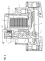
- An inventive impulse switch according to FIG 1 has a housing 1, in which a magnet system 2 is integrated. This moves a hinged armature. 3
- a switch plunger 4 interacts with a ratchet wheel 5, which switches on and off a contact system 7 via a contact spring band 6.
- the switch plunger 4 has substantially an elongated extent and acts with its first end 41 with the 5 ratchet together. At the opposite second end 42, it projects out of the housing 1 for manual actuation.
- a coil spring 8 is supported on the switching plunger 4.
- the hinged armature 3 of the magnet system At the other end of the coil spring 8 is the hinged armature 3 of the magnet system.
- the plunger 4 has a support or a projection 43 on which the hinged armature 3 rests when the coil spring 8 is depressed to a certain extent.
- a multi-function spring 9 is fixed to the plunger 4, with both a locking function and an armature reset can be achieved.
- the switch-on is first described.
- the electromagnet 2 is energized and the hinged armature 3 is not attracted to it.
- the hinged armature 3 is approximately at an angle of 7.5 ° relative to the end face of the electromagnet second
- the coil spring 8 is practically in the relaxed state and has in this example in the basic position a length of 7.2 mm. Further, the switching plunger 4 is reset by the multi-function spring 9, so that its operating portion 42 protrudes from the housing 1 about 4.8 mm.
- the ratchet wheel 5 presses the contact spring band 6 down so that the contact system 7 is in the open state.
- the ratchet wheel 5 To turn on the surge switch, the ratchet wheel 5 must be rotated so that the contact system 7 can close.
- the impulse switch is shown shortly after the activation of the coil or the magnet system 2 in a first position for the switch-on.
- the hinged armature 3 is already tightened so far that it assumes an angular position of 5.3 °.
- the plunger 4 just touches the ratchet wheel 5. Therefore, it protrudes only 3.6 mm from the housing 1.
- the length the coil spring 8 is almost unchanged in this state.
- the ratchet 5 is now unscrewed for the switch from its normal position.
- the effort required for this is relatively low. Therefore, the length of the spring 8 remains unchanged, while the hinged armature 3 is pulled in the angular position 3.5 °.
- the ratchet wheel 5 After the complete pulling down of the hinged armature 3 on the front side of the electromagnet 2, the ratchet wheel 5 has completed a one-eighth revolution. In this position, the ratchet wheel 5 no longer pushes the contact spring band 6 down so that the contact system 7 is closed and the impulse switch is in the switched-on state. In the illustration of FIG 4, the magnet system or the coil 2 is already energy-free, so that the multi-function spring 9 has pushed the plunger 4 and the hinged armature 3 back into their initial positions (see FIG 1).
- the switching mechanism d. H. the ratchet wheel 5 in cooperation with the contact spring band 6 more power than when switching.
- the reason for this lies in the frictional forces between the ratchet wheel 5 and the contact spring band 6 and the restoring force of the contact spring band 6.
- the frictional forces are determined by the shapes and materials of the components 5 and 6. However, these friction and restoring forces change within one-eighth revolution of the ratchet wheel 5.
- the magnet system at the beginning of the movement of the hinged armature 3 has relatively little force and would have problems here, the switching mechanism 5, 6 to drive.
- the components of the switching mechanism are therefore designed so that pulled in the first part of the movement for the turn-off of the hinged armature 3 under rotation of the ratchet wheel 5 down can be without counteracting frictional forces and restoring forces to a greater extent. These conditions apply up to a position which is shown in FIG.
- the hinged armature has an angular position of 2.5 ° and the coil spring 8, the relaxed length of 7.2 mm.
- the eighth-rotation of the ratchet wheel 5 take the friction forces between the ratchet wheel 5 and the contact spring band 6 again.
- the hinged armature 3 has already reached an end position of 0 °, as shown in FIG 7, but the energy stored in the coil spring 8 is sufficient to turn the ratchet wheel 5 in its final position.
- the contact spring band 6 is pressed down, so that the contact system 7 opens and the surge switch is in the off state.
- the force accumulator realized by the helical spring 8 is "unloaded" again in this end position.
- the manufacturing technology simple part such as the coil spring 8 takes over by its spring characteristics (characteristic, force) and the coupling of hinged armature 3 and plunger 4 basic control functions.
- the time shift of the force demand to the rear by means of force-path storage and power output with ensuring a defined starting position for further switching operations resulting in power transmission to Griffinerzielung in the mechanics can be realized by a single component during the turn-off.
Landscapes
- Physics & Mathematics (AREA)
- Electromagnetism (AREA)
- Push-Button Switches (AREA)
- Electromagnets (AREA)
- Communication Control (AREA)
- Devices For Checking Fares Or Tickets At Control Points (AREA)
- Air Bags (AREA)
- Reciprocating, Oscillating Or Vibrating Motors (AREA)
- Driving Mechanisms And Operating Circuits Of Arc-Extinguishing High-Tension Switches (AREA)
Applications Claiming Priority (1)
| Application Number | Priority Date | Filing Date | Title |
|---|---|---|---|
| DE102004042791A DE102004042791B3 (de) | 2004-09-03 | 2004-09-03 | Schrittschaltvorrichtung für ein Installationsgerät und entsprechendes Verfahren |
Publications (3)
| Publication Number | Publication Date |
|---|---|
| EP1632971A2 true EP1632971A2 (fr) | 2006-03-08 |
| EP1632971A3 EP1632971A3 (fr) | 2007-05-30 |
| EP1632971B1 EP1632971B1 (fr) | 2009-10-14 |
Family
ID=35429541
Family Applications (1)
| Application Number | Title | Priority Date | Filing Date |
|---|---|---|---|
| EP05107807A Expired - Lifetime EP1632971B1 (fr) | 2004-09-03 | 2005-08-25 | Dispositif pas à pas pour un appareil d'installation et procédé correspondant |
Country Status (3)
| Country | Link |
|---|---|
| EP (1) | EP1632971B1 (fr) |
| AT (1) | ATE445906T1 (fr) |
| DE (2) | DE102004042791B3 (fr) |
Cited By (1)
| Publication number | Priority date | Publication date | Assignee | Title |
|---|---|---|---|---|
| WO2010139113A1 (fr) * | 2009-06-03 | 2010-12-09 | Abb瑞士有限公司 | Commutateur modulaire basse tension |
Family Cites Families (7)
| Publication number | Priority date | Publication date | Assignee | Title |
|---|---|---|---|---|
| US2902559A (en) * | 1957-06-06 | 1959-09-01 | Zenith Radio Corp | Switching apparatus |
| DE1858353U (de) * | 1961-12-15 | 1962-09-13 | Bosch Gmbh Robert | Elektromagnetischer schalter, insbesondere fuer elektrische anlagen von kraftfahrzeugen. |
| DE1813067C3 (de) * | 1968-12-06 | 1980-10-09 | Schutzapparate-Gesellschaft Paris + Co Mbh Kg, 5885 Schalksmuehle | Elektromagnetischer Fernschalter |
| DE3519546A1 (de) * | 1985-05-31 | 1986-12-04 | E. Dold & Söhne KG, 7743 Furtwangen | Elektromagnetisches schrittschaltrelais |
| DE19903751A1 (de) * | 1999-01-30 | 2000-08-24 | Eltako Gmbh Schaltgeraete | Elektromechanisches Schaltgerät |
| DE10243772C1 (de) * | 2002-09-20 | 2003-11-20 | Siemens Ag | Elektromagnetischer Stromstoßschalter |
| DE10244182B3 (de) * | 2002-09-23 | 2004-02-26 | Siemens Ag | Elektrisches Schaltgerät mit Schaltstellungsanzeige |
-
2004
- 2004-09-03 DE DE102004042791A patent/DE102004042791B3/de not_active Expired - Fee Related
-
2005
- 2005-08-25 EP EP05107807A patent/EP1632971B1/fr not_active Expired - Lifetime
- 2005-08-25 AT AT05107807T patent/ATE445906T1/de not_active IP Right Cessation
- 2005-08-25 DE DE502005008308T patent/DE502005008308D1/de not_active Expired - Lifetime
Cited By (1)
| Publication number | Priority date | Publication date | Assignee | Title |
|---|---|---|---|---|
| WO2010139113A1 (fr) * | 2009-06-03 | 2010-12-09 | Abb瑞士有限公司 | Commutateur modulaire basse tension |
Also Published As
| Publication number | Publication date |
|---|---|
| DE102004042791B3 (de) | 2006-03-30 |
| ATE445906T1 (de) | 2009-10-15 |
| EP1632971B1 (fr) | 2009-10-14 |
| DE502005008308D1 (de) | 2009-11-26 |
| EP1632971A3 (fr) | 2007-05-30 |
Similar Documents
| Publication | Publication Date | Title |
|---|---|---|
| DE69505535T2 (de) | Elektrisch gesteuerter auslösemechanismus | |
| DE112013004270B4 (de) | Schaltersteuerelement für schalter und drucktaste mit einem solchen schaltersteuerelement | |
| DE2224555C3 (de) | Schaltwerk mit Sprungmechanik für Schalter und elektrische Singalgeber | |
| EP0900467A1 (fr) | Procede et dispositif pour produire de l'energie electrique pour assurer le fonctionnement de petits appareils electriques | |
| DE102014209192A1 (de) | Schaltvorrichtung für einen Funktaster, Funktaster und Verfahren zum Erzeugen eines Schaltsignals eines Funktasters | |
| EP1145267A1 (fr) | Relais destine notamment a un dispositif de demarrage | |
| EP2766915B1 (fr) | Mécanisme de verrouillage pour un poussoir d'enclenchement d'un disjoncteur | |
| DE2831808A1 (de) | Hydraulische antriebsvorrichtung | |
| DE69407939T2 (de) | Elektrischer Momentanschalter mit mechanischer Sperrvorrichtung | |
| EP1632971B1 (fr) | Dispositif pas à pas pour un appareil d'installation et procédé correspondant | |
| EP1292784A1 (fr) | Mecanisme de verrouillage et de deverrouillage a electroaimant | |
| DE102011018639A1 (de) | Rastsystem, insbesondere für ein Kraftfahrzeug | |
| DE2417236C3 (de) | Schalterantrieb mit einem Linearmotor | |
| DE102007046512A1 (de) | Schaltelement zur mechanischen Verbindung mit einem Betätiger | |
| EP2219905B1 (fr) | Système de déverrouillage réversible d'un dispositif de sécurité dans des véhicules à moteur | |
| DE19845800B4 (de) | Niederspannungs-Leistungsschalter mit einer Einrichtung zur Rückstellung eines Haftmagnetauslösers | |
| DE3905079C2 (fr) | ||
| DE19649979C1 (de) | Elektrodynamischer Antrieb, insbesondere für Hochspannungsschaltgeräte | |
| DE3243108A1 (de) | Vorrichtung zum ein- und ausschalten eines elektrischen verbrauchers in einem kraftfahrzeug | |
| DE29910337U1 (de) | Notausschütz | |
| EP0688031B1 (fr) | Interrupteur de puissance à organe de signalisation de l'état d'un accumulateur d'énergie | |
| DE2335511C3 (de) | Schalter, insbesondere elektromagnetischer Schalter | |
| DE102015218700A1 (de) | Anordnung und Verfahren zum Antreiben eines Leistungsschalters mit gleichen Richtungen der Feder- und Antriebskraft | |
| DE19603921C1 (de) | Druckschalter | |
| DE102021201524A1 (de) | Vorrichtung zum Spannen eines Energiespeichers und Verfahren zum Spannen eines Energiespeichers |
Legal Events
| Date | Code | Title | Description |
|---|---|---|---|
| PUAI | Public reference made under article 153(3) epc to a published international application that has entered the european phase |
Free format text: ORIGINAL CODE: 0009012 |
|
| AK | Designated contracting states |
Kind code of ref document: A2 Designated state(s): AT BE BG CH CY CZ DE DK EE ES FI FR GB GR HU IE IS IT LI LT LU LV MC NL PL PT RO SE SI SK TR |
|
| AX | Request for extension of the european patent |
Extension state: AL BA HR MK YU |
|
| PUAL | Search report despatched |
Free format text: ORIGINAL CODE: 0009013 |
|
| AK | Designated contracting states |
Kind code of ref document: A3 Designated state(s): AT BE BG CH CY CZ DE DK EE ES FI FR GB GR HU IE IS IT LI LT LU LV MC NL PL PT RO SE SI SK TR |
|
| AX | Request for extension of the european patent |
Extension state: AL BA HR MK YU |
|
| 17P | Request for examination filed |
Effective date: 20070507 |
|
| AKX | Designation fees paid |
Designated state(s): AT BE BG CH CY CZ DE DK EE ES FI FR GB GR HU IE IS IT LI LT LU LV MC NL PL PT RO SE SI SK TR |
|
| GRAP | Despatch of communication of intention to grant a patent |
Free format text: ORIGINAL CODE: EPIDOSNIGR1 |
|
| GRAS | Grant fee paid |
Free format text: ORIGINAL CODE: EPIDOSNIGR3 |
|
| GRAA | (expected) grant |
Free format text: ORIGINAL CODE: 0009210 |
|
| AK | Designated contracting states |
Kind code of ref document: B1 Designated state(s): AT BE BG CH CY CZ DE DK EE ES FI FR GB GR HU IE IS IT LI LT LU LV MC NL PL PT RO SE SI SK TR |
|
| REG | Reference to a national code |
Ref country code: GB Ref legal event code: FG4D Free format text: NOT ENGLISH |
|
| REG | Reference to a national code |
Ref country code: CH Ref legal event code: EP |
|
| REG | Reference to a national code |
Ref country code: IE Ref legal event code: FG4D |
|
| REF | Corresponds to: |
Ref document number: 502005008308 Country of ref document: DE Date of ref document: 20091126 Kind code of ref document: P |
|
| LTIE | Lt: invalidation of european patent or patent extension |
Effective date: 20091014 |
|
| NLV1 | Nl: lapsed or annulled due to failure to fulfill the requirements of art. 29p and 29m of the patents act | ||
| PG25 | Lapsed in a contracting state [announced via postgrant information from national office to epo] |
Ref country code: FI Free format text: LAPSE BECAUSE OF FAILURE TO SUBMIT A TRANSLATION OF THE DESCRIPTION OR TO PAY THE FEE WITHIN THE PRESCRIBED TIME-LIMIT Effective date: 20091014 Ref country code: ES Free format text: LAPSE BECAUSE OF FAILURE TO SUBMIT A TRANSLATION OF THE DESCRIPTION OR TO PAY THE FEE WITHIN THE PRESCRIBED TIME-LIMIT Effective date: 20100125 Ref country code: SE Free format text: LAPSE BECAUSE OF FAILURE TO SUBMIT A TRANSLATION OF THE DESCRIPTION OR TO PAY THE FEE WITHIN THE PRESCRIBED TIME-LIMIT Effective date: 20091014 Ref country code: PT Free format text: LAPSE BECAUSE OF FAILURE TO SUBMIT A TRANSLATION OF THE DESCRIPTION OR TO PAY THE FEE WITHIN THE PRESCRIBED TIME-LIMIT Effective date: 20100215 Ref country code: IS Free format text: LAPSE BECAUSE OF FAILURE TO SUBMIT A TRANSLATION OF THE DESCRIPTION OR TO PAY THE FEE WITHIN THE PRESCRIBED TIME-LIMIT Effective date: 20100214 Ref country code: LT Free format text: LAPSE BECAUSE OF FAILURE TO SUBMIT A TRANSLATION OF THE DESCRIPTION OR TO PAY THE FEE WITHIN THE PRESCRIBED TIME-LIMIT Effective date: 20091014 |
|
| REG | Reference to a national code |
Ref country code: IE Ref legal event code: FD4D |
|
| PG25 | Lapsed in a contracting state [announced via postgrant information from national office to epo] |
Ref country code: PL Free format text: LAPSE BECAUSE OF FAILURE TO SUBMIT A TRANSLATION OF THE DESCRIPTION OR TO PAY THE FEE WITHIN THE PRESCRIBED TIME-LIMIT Effective date: 20091014 Ref country code: LV Free format text: LAPSE BECAUSE OF FAILURE TO SUBMIT A TRANSLATION OF THE DESCRIPTION OR TO PAY THE FEE WITHIN THE PRESCRIBED TIME-LIMIT Effective date: 20091014 Ref country code: SI Free format text: LAPSE BECAUSE OF FAILURE TO SUBMIT A TRANSLATION OF THE DESCRIPTION OR TO PAY THE FEE WITHIN THE PRESCRIBED TIME-LIMIT Effective date: 20091014 |
|
| PG25 | Lapsed in a contracting state [announced via postgrant information from national office to epo] |
Ref country code: DK Free format text: LAPSE BECAUSE OF FAILURE TO SUBMIT A TRANSLATION OF THE DESCRIPTION OR TO PAY THE FEE WITHIN THE PRESCRIBED TIME-LIMIT Effective date: 20091014 Ref country code: RO Free format text: LAPSE BECAUSE OF FAILURE TO SUBMIT A TRANSLATION OF THE DESCRIPTION OR TO PAY THE FEE WITHIN THE PRESCRIBED TIME-LIMIT Effective date: 20091014 Ref country code: BG Free format text: LAPSE BECAUSE OF FAILURE TO SUBMIT A TRANSLATION OF THE DESCRIPTION OR TO PAY THE FEE WITHIN THE PRESCRIBED TIME-LIMIT Effective date: 20100114 Ref country code: IE Free format text: LAPSE BECAUSE OF FAILURE TO SUBMIT A TRANSLATION OF THE DESCRIPTION OR TO PAY THE FEE WITHIN THE PRESCRIBED TIME-LIMIT Effective date: 20091014 Ref country code: EE Free format text: LAPSE BECAUSE OF FAILURE TO SUBMIT A TRANSLATION OF THE DESCRIPTION OR TO PAY THE FEE WITHIN THE PRESCRIBED TIME-LIMIT Effective date: 20091014 |
|
| PLBE | No opposition filed within time limit |
Free format text: ORIGINAL CODE: 0009261 |
|
| STAA | Information on the status of an ep patent application or granted ep patent |
Free format text: STATUS: NO OPPOSITION FILED WITHIN TIME LIMIT |
|
| PG25 | Lapsed in a contracting state [announced via postgrant information from national office to epo] |
Ref country code: CZ Free format text: LAPSE BECAUSE OF FAILURE TO SUBMIT A TRANSLATION OF THE DESCRIPTION OR TO PAY THE FEE WITHIN THE PRESCRIBED TIME-LIMIT Effective date: 20091014 Ref country code: SK Free format text: LAPSE BECAUSE OF FAILURE TO SUBMIT A TRANSLATION OF THE DESCRIPTION OR TO PAY THE FEE WITHIN THE PRESCRIBED TIME-LIMIT Effective date: 20091014 |
|
| 26N | No opposition filed |
Effective date: 20100715 |
|
| PG25 | Lapsed in a contracting state [announced via postgrant information from national office to epo] |
Ref country code: GR Free format text: LAPSE BECAUSE OF FAILURE TO SUBMIT A TRANSLATION OF THE DESCRIPTION OR TO PAY THE FEE WITHIN THE PRESCRIBED TIME-LIMIT Effective date: 20100115 |
|
| BERE | Be: lapsed |
Owner name: SIEMENS A.G. Effective date: 20100831 |
|
| PG25 | Lapsed in a contracting state [announced via postgrant information from national office to epo] |
Ref country code: MC Free format text: LAPSE BECAUSE OF NON-PAYMENT OF DUE FEES Effective date: 20100831 |
|
| REG | Reference to a national code |
Ref country code: CH Ref legal event code: PL |
|
| GBPC | Gb: european patent ceased through non-payment of renewal fee |
Effective date: 20100825 |
|
| PG25 | Lapsed in a contracting state [announced via postgrant information from national office to epo] |
Ref country code: CH Free format text: LAPSE BECAUSE OF NON-PAYMENT OF DUE FEES Effective date: 20100831 Ref country code: LI Free format text: LAPSE BECAUSE OF NON-PAYMENT OF DUE FEES Effective date: 20100831 |
|
| PG25 | Lapsed in a contracting state [announced via postgrant information from national office to epo] |
Ref country code: BE Free format text: LAPSE BECAUSE OF NON-PAYMENT OF DUE FEES Effective date: 20100831 |
|
| PG25 | Lapsed in a contracting state [announced via postgrant information from national office to epo] |
Ref country code: GB Free format text: LAPSE BECAUSE OF NON-PAYMENT OF DUE FEES Effective date: 20100825 |
|
| PG25 | Lapsed in a contracting state [announced via postgrant information from national office to epo] |
Ref country code: AT Free format text: LAPSE BECAUSE OF NON-PAYMENT OF DUE FEES Effective date: 20100825 |
|
| PG25 | Lapsed in a contracting state [announced via postgrant information from national office to epo] |
Ref country code: CY Free format text: LAPSE BECAUSE OF FAILURE TO SUBMIT A TRANSLATION OF THE DESCRIPTION OR TO PAY THE FEE WITHIN THE PRESCRIBED TIME-LIMIT Effective date: 20091014 |
|
| PG25 | Lapsed in a contracting state [announced via postgrant information from national office to epo] |
Ref country code: HU Free format text: LAPSE BECAUSE OF FAILURE TO SUBMIT A TRANSLATION OF THE DESCRIPTION OR TO PAY THE FEE WITHIN THE PRESCRIBED TIME-LIMIT Effective date: 20100415 Ref country code: LU Free format text: LAPSE BECAUSE OF NON-PAYMENT OF DUE FEES Effective date: 20100825 Ref country code: NL Free format text: LAPSE BECAUSE OF FAILURE TO SUBMIT A TRANSLATION OF THE DESCRIPTION OR TO PAY THE FEE WITHIN THE PRESCRIBED TIME-LIMIT Effective date: 20091014 |
|
| PG25 | Lapsed in a contracting state [announced via postgrant information from national office to epo] |
Ref country code: TR Free format text: LAPSE BECAUSE OF FAILURE TO SUBMIT A TRANSLATION OF THE DESCRIPTION OR TO PAY THE FEE WITHIN THE PRESCRIBED TIME-LIMIT Effective date: 20091014 |
|
| REG | Reference to a national code |
Ref country code: FR Ref legal event code: PLFP Year of fee payment: 12 |
|
| PGFP | Annual fee paid to national office [announced via postgrant information from national office to epo] |
Ref country code: IT Payment date: 20160830 Year of fee payment: 12 |
|
| PGFP | Annual fee paid to national office [announced via postgrant information from national office to epo] |
Ref country code: DE Payment date: 20161020 Year of fee payment: 12 |
|
| REG | Reference to a national code |
Ref country code: FR Ref legal event code: PLFP Year of fee payment: 13 |
|
| PGFP | Annual fee paid to national office [announced via postgrant information from national office to epo] |
Ref country code: FR Payment date: 20170814 Year of fee payment: 13 |
|
| REG | Reference to a national code |
Ref country code: DE Ref legal event code: R119 Ref document number: 502005008308 Country of ref document: DE |
|
| PG25 | Lapsed in a contracting state [announced via postgrant information from national office to epo] |
Ref country code: DE Free format text: LAPSE BECAUSE OF NON-PAYMENT OF DUE FEES Effective date: 20180301 |
|
| PG25 | Lapsed in a contracting state [announced via postgrant information from national office to epo] |
Ref country code: IT Free format text: LAPSE BECAUSE OF NON-PAYMENT OF DUE FEES Effective date: 20170825 |
|
| PG25 | Lapsed in a contracting state [announced via postgrant information from national office to epo] |
Ref country code: FR Free format text: LAPSE BECAUSE OF NON-PAYMENT OF DUE FEES Effective date: 20180831 |