EP1632971A2 - Stepper device for an apparatus of an electrical installation and corresponding method - Google Patents
Stepper device for an apparatus of an electrical installation and corresponding method Download PDFInfo
- Publication number
- EP1632971A2 EP1632971A2 EP05107807A EP05107807A EP1632971A2 EP 1632971 A2 EP1632971 A2 EP 1632971A2 EP 05107807 A EP05107807 A EP 05107807A EP 05107807 A EP05107807 A EP 05107807A EP 1632971 A2 EP1632971 A2 EP 1632971A2
- Authority
- EP
- European Patent Office
- Prior art keywords
- plunger
- movable component
- movement
- coupling element
- switching
- Prior art date
- Legal status (The legal status is an assumption and is not a legal conclusion. Google has not performed a legal analysis and makes no representation as to the accuracy of the status listed.)
- Granted
Links
Images


Classifications
-
- H—ELECTRICITY
- H01—ELECTRIC ELEMENTS
- H01H—ELECTRIC SWITCHES; RELAYS; SELECTORS; EMERGENCY PROTECTIVE DEVICES
- H01H51/00—Electromagnetic relays
- H01H51/02—Non-polarised relays
- H01H51/04—Non-polarised relays with single armature; with single set of ganged armatures
- H01H51/06—Armature is movable between two limit positions of rest and is moved in one direction due to energisation of an electromagnet and after the electromagnet is de-energised is returned by energy stored during the movement in the first direction, e.g. by using a spring, by using a permanent magnet, by gravity
- H01H51/08—Contacts alternately opened and closed by successive cycles of energisation and de-energisation of the electromagnet, e.g. by use of a ratchet
- H01H51/082—Contacts alternately opened and closed by successive cycles of energisation and de-energisation of the electromagnet, e.g. by use of a ratchet using rotating ratchet mechanism
- H01H51/086—Contacts alternately opened and closed by successive cycles of energisation and de-energisation of the electromagnet, e.g. by use of a ratchet using rotating ratchet mechanism with radial ratchet elements
Landscapes
- Physics & Mathematics (AREA)
- Electromagnetism (AREA)
- Push-Button Switches (AREA)
- Electromagnets (AREA)
- Reciprocating, Oscillating Or Vibrating Motors (AREA)
- Driving Mechanisms And Operating Circuits Of Arc-Extinguishing High-Tension Switches (AREA)
- Devices For Checking Fares Or Tickets At Control Points (AREA)
- Air Bags (AREA)
- Communication Control (AREA)
Abstract
Description
Die vorliegende Erfindung betrifft eine Schrittschaltvorrichtung für ein Installationsgerät mit einem Stößel zu Betätigung eines Schaltrads des Installationsgeräts und einer Magneteinrichtung einschließlich einer beweglichen Komponente zum Bewegen des Stößels. Darüber hinaus betrifft die vorliegende Erfindung ein entsprechendes Verfahren zum Schalten eines Schrittschaltwerks.The present invention relates to a stepper device for an installation device with a plunger for operating a ratchet wheel of the installation device and a magnet device including a movable component for moving the plunger. Moreover, the present invention relates to a corresponding method for switching a stepping mechanism.
Bei Stromstoßschaltern mit Schrittschaltwerk ist es notwendig, die nicht-lineare, angenähert exponentielle Kraftlieferung eines ansteuernden Klappanker-Magnetsystems auf die ebenfalls nicht-lineare, schaltzustandsabhängige Kraftforderung der Schaltmechanik zeitlich abzustimmen. Dabei ist zu beachten, dass der Klappanker bei seiner Bewegung aus der Ruhestellung heraus zunächst verhältnismäßig geringe Kraft liefert. Die von dem Schrittschaltwerk geforderte Kraft hängt von der Reibung der Mechanik und von Rückstellkräften federgestützter Komponenten ab.With impulse switches with stepping mechanism, it is necessary to synchronize the non-linear, approximately exponential power delivery of a driving hinged armature magnet system on the also non-linear, switching state-dependent power demand of the switching mechanism in time. It should be noted that the hinged armature initially delivers relatively low power during its movement from the rest position out. The force required by the stepper mechanism depends on the friction of the mechanics and restoring forces of spring-supported components.
Darüber hinaus besteht die Problematik, dass die Magnetsysteme hinsichtlich des Bauraums optimiert sein müssen. Dies bedeutet, dass der zur Verfügung stehende Bauraum oftmals nur den Einbau kleiner Magnetsysteme mit entsprechend geringer Kraftlieferung bzw. kurzen Hebelverhältnissen und Klappankerabmessungen erlaubt. Damit ergibt sich aufgrund der geringen Stößelhübe eine schwierige Abstimmung der Mechanik, was geringe Kräfte und damit ungünstig kleine Kontaktabstände für das Stromübertragungssystem zur Folge hat. Derartige Systeme sind beispielsweise in der Patentschrift DE 35 19 546 C2 beschrieben. Dabei ist der Klappanker mittels Klemmung direkt an den Schaltstößel gekoppelt. Gegebenenfalls sorgt bei einer schwimmenden Lagerung der Komponenten eine Druckfeder für eine spielfreie Verbindung, so dass ein Brummen des Magnetsystems verhindert werden kann.In addition, there is the problem that the magnet systems must be optimized in terms of space. This means that the available space often allows only the installation of small magnet systems with correspondingly low power delivery or short lever ratios and hinged armature dimensions. This results in a difficult tuning of the mechanism due to the low ram strokes, resulting in low forces and thus unfavorably small contact distances for the power transmission system result. Such systems are described for example in the patent DE 35 19 546 C2. The hinged armature is coupled by clamping directly to the switch plunger. Optionally, in a floating mounting of the components, a compression spring provides for a play-free connection, so that a hum of the magnet system can be prevented.
Des Weiteren ist aus der Patentschrift EP 1 024 511 eine starre Kopplung zwischen Klappanker und Stößel des Schrittschaltwerks bekannt.Furthermore, the patent EP 1 024 511 discloses a rigid coupling between hinged armature and plunger of the stepping mechanism.
Die Aufgabe der vorliegenden Erfindung besteht darin, die Kraftlieferung des Magnetsystems besser auf die Kraftforderung der Schaltmechanik abzustimmen.The object of the present invention is to better tune the power delivery of the magnet system to the force demand of the switching mechanism.
Erfindungsgemäß wird diese Aufgabe gelöst durch eine Schrittschaltvorrichtung für ein Installationsgerät mit einem Stößel zur Betätigung eines Schaltrads des Installationsgeräts und einer Magneteinrichtung einschließlich einer beweglichen Komponente zum Bewegen des Stößels, sowie einem Kopplungselement zum federelastischen Koppeln der beweglichen Komponente an den Stößel.According to the invention this object is achieved by a step switching device for an installation device with a plunger for actuating a ratchet wheel of the installation device and a magnetic device including a movable component for moving the plunger, and a coupling element for resiliently coupling the movable component to the plunger.
Darüber hinaus ist erfindungsgemäß vorgesehen ein Verfahren zum Schalten eines Schrittschaltwerks für ein Installationsgerät durch Bewegen einer beweglichen Komponente einer Magneteinrichtung und Übertragen der Bewegung der beweglichen Komponente auf einen Stößel zur Durchführung eines Schaltvorgangs, sowie Speichern eines Teils der Energie, die von der Magneteinrichtung auf die bewegliche Komponente übertragen wird, in einem Kopplungselement, das die bewegliche Komponente an den Stößel federelastisch koppelt, im Wesentlichen vor dem Übertragen der Bewegung der beweglichen Komponente auf den Stößel und Abgeben der gespeicherten Energie an den Stößel für den Schaltvorgang im letzten Abschnitt der Bewegung des Stößels.Moreover, the present invention provides a method of switching a stepper for an installation device by moving a movable component of a magnetic device and transmitting the movement of the movable component on a plunger for performing a switching operation, and storing a portion of the energy from the magnetic device to the movable Component is transferred, in a coupling element, which elastically couples the movable component to the plunger, substantially before transmitting the movement of the movable component to the plunger and outputting the stored energy to the plunger for the switching operation in the last portion of the movement of the plunger.
In vorteilhafter Weise kann somit die Kraftlieferung durch die Magneteinrichtung exakt an die Kraftforderung eines Schaltwerks in Bezug auf den zeitlichen Kraftverlauf angepasst werden. Darüber hinaus wird durch das Kopplungselement sozusagen eine Entkopplung der beiden Systeme Steuer- und Lastkreis erzielt und somit eine "Brummneigung" des Magnetsystems bei Dauerlast reduziert. Des Weiteren kann durch das Kopplungselement eine vereinfachte maßliche Abstimmung der mechanischen Komponenten: Magnetsystem, Stößel, Schaltrad und Kontaktfederband erreicht werden.Advantageously, thus the power supply can be adjusted by the magnetic device exactly to the power demand of a rear derailleur with respect to the temporal force curve. In addition, by the coupling element achieved a decoupling of the two systems control and load circuit and thus reduces a "rumbling" of the magnet system under continuous load. Furthermore, a simplified dimensional coordination of the mechanical components: magnet system, ram, ratchet wheel and contact spring band can be achieved by the coupling element.
Vorzugsweise besitzt der Stößel einen Vorsprung zum unmittelbaren Zusammenwirken mit der beweglichen Komponente der Magneteinrichtung. Damit kann in einem gewissen Bewegungsbereich die Bewegung der beweglichen Komponente des Magnetsystems direkt auf den Stößel übertragen werden, also ohne elastische Wirkung der Feder.Preferably, the plunger has a projection for direct cooperation with the movable component of the magnetic device. Thus, in a certain range of motion, the movement of the movable component of the magnet system can be transmitted directly to the plunger, so without elastic action of the spring.
Entsprechend einer besonders bevorzugten Ausgestaltung umfasst das Kopplungselement eine Schraubenfeder. Diese eignet sich ausgezeichnet, um eine Energie von dem Magnetsystem aufzunehmen und nahezu vollständig für die Bewegung des Stößels am Ende seiner Bewegung wieder abzugeben.According to a particularly preferred embodiment, the coupling element comprises a coil spring. This is excellent for absorbing energy from the magnet system and releasing it almost completely for the movement of the plunger at the end of its movement.
Die bewegliche Komponente der Magneteinrichtung wird günstigerweise durch einen Klappanker realisiert, der mit dem Kopplungselement in Wirkverbindung steht. Ein derartiger Klappanker eignet sich in bewährter Weise, einen Stößel eines Schrittschaltwerks zu betätigen. Insbesondere kann der Klappanker am Anfang seiner Bewegung eine Schraubenfeder eindrücken, ohne dass sich das kraftfordernde Kontaktfederband bzw. das Schaltwerk bewegt. In der Endstellung des Klappankers, d. h. im angezogenen Zustand, führt dann die Schraubenfeder die Bewegung des Stößels fort, womit das Schaltrad betätigt wird.The movable component of the magnetic device is conveniently realized by a hinged armature, which is in operative connection with the coupling element. Such a hinged armature is in a proven way to operate a plunger of a stepper. In particular, the hinged armature can press in at the beginning of its movement a coil spring without the force-demanding contact spring band or the rear derailleur moves. In the end position of the hinged anchor, d. H. in the tightened state, then the coil spring continues the movement of the plunger, whereby the ratchet wheel is actuated.
In einer bevorzugten Ausgestaltung ist ein Stromstoßschalter mit der erfindungsgemäßen Schrittschaltvorrichtung versehen. Dabei dient die Schrittschaltvorrichtung bzw. das Schrittschaltwerk zur Erzielung der Schaltvorgänge des Stromstoßschalters.In a preferred embodiment, an impulse switch is provided with the step switching device according to the invention. The stepping device or the stepping mechanism is used to achieve the switching operations of the surge switch.
Entsprechend einer weiteren Ausführungsform kann der Stromstoßschalter ein Gehäuse aufweisen, aus dem der Stößel zur manuellen Betätigung herausragt. Dadurch ist der Stromstoßschalter nicht nur elektrisch, sondern auch manuell betätigbar.According to a further embodiment, the impulse switch may comprise a housing from which the plunger protrudes for manual actuation. As a result, the impulse switch is not only electrically, but also manually operated.
Die vorliegende Erfindung wird nun anhand der beigefügten Zeichnungen näher erläutert, in denen zeigen:
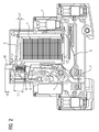
- FIG 1
- eine Schnittansicht durch einen erfindungsgemäßen Stromstoßschalter in einem ausgeschalteten Zustand;
- FIG 2
- den Stromstoßschalter von FIG 1 bei einem Einschaltvorgang in einer ersten Stellung;
- FIG 3
- den Stromstoßschalter beim Einschaltvorgang in einer zweiten Stellung;
- FIG 4
- den Stromstoßschalter im eingeschalteten Zustand;
- FIG 5
- den Stromstoßschalter beim Ausschaltvorgang in einer ersten Stellung;
- FIG 6
- den Stromstoßschalter beim Ausschaltvorgang in einer zweiten Stellung; und
- FIG 7
- den Stromstoßschalter im Ausschaltzustand bei aktivem Magnetsystem.
- FIG. 1
- a sectional view through an impulse switch according to the invention in an off state;
- FIG. 2
- the impulse switch of FIG 1 at a power-on in a first position;
- FIG. 3
- the impulse switch during the switch-on in a second position;
- FIG. 4
- the surge switch in the on state;
- FIG. 5
- the surge switch during the turn-off in a first position;
- FIG. 6
- the surge switch during the turn-off in a second position; and
- FIG. 7
- the impulse switch in the off state with active magnet system.
Das nachfolgend näher geschilderte Ausführungsbeispiel stellt eine bevorzugte Ausführungsform der vorliegenden Erfindung dar.The embodiment described in more detail below represents a preferred embodiment of the present invention.
Ein erfindungsgemäßer Stromstoßschalter entsprechend FIG 1 besitzt ein Gehäuse 1, in das ein Magnetsystem 2 integriert ist. Dieses bewegt einen Klappanker 3.An inventive impulse switch according to FIG 1 has a housing 1, in which a
Ein Schaltstößel 4 wirkt mit einem Schaltrad 5 zusammen, das über ein Kontaktfederband 6 ein Kontaktsystem 7 ein- und ausschaltet.A
Der Schaltstößel 4 besitzt im Wesentlichen eine längliche Erstreckung und wirkt mit seinem ersten Ende 41 mit dem Schaltrad 5 zusammen. An dem gegenüberliegenden zweiten Ende 42 ragt er zur manuellen Betätigung aus dem Gehäuse 1 heraus.The
An dem Schaltstößel 4 ist eine Schraubenfeder 8 abgestützt. An dem anderen Ende der Schraubenfeder 8 liegt der Klappanker 3 des Magnetsystems auf. Des Weiteren besitzt der Stößel 4 eine Auflage bzw. einen Vorsprung 43, auf dem der Klappanker 3 aufliegt, wenn die Schraubenfeder 8 über ein gewisses Maß niedergedrückt wird. Schließlich ist an dem Stößel 4 eine Multifunktionsfeder 9 befestigt, mit der sowohl ein Rastfunktion als auch eine Ankerrückstellung erzielbar ist.On the switching
Mit den FIG 1 bis 4 wird zunächst der Einschaltvorgang beschrieben. In der in FIG 1 dargestellten Position ist der Elektromagnet 2 energielos und der Klappanker 3 ist von ihm nicht angezogen. Dementsprechend steht in dem vorliegenden Beispiel der Klappanker 3 etwa in einem Winkel von 7,5° gegenüber der Stirnseite des Elektromagneten 2.With the 1 to 4, the switch-on is first described. In the position shown in FIG 1, the
Die Schraubenfeder 8 befindet sich praktisch im entspannten Zustand und besitzt in diesem Beispiel in der Grundstellung eine Länge von 7,2 mm. Ferner ist der Schaltstößel 4 durch die Multifunktionsfeder 9 zurückgestellt, so dass sein Betätigungsabschnitt 42 etwa 4,8 mm aus dem Gehäuse 1 ragt.The
In dieser Grundstellung drückt das Schaltrad 5 das Kontaktfederband 6 nach unten, so dass sich das Kontaktsystem 7 im geöffneten Zustand befindet. Zum Einschalten des Stromstoßschalters muss das Schaltrad 5 gedreht werden, so dass das Kontaktsystem 7 schließen kann.In this basic position, the
In FIG 2 ist der Stromstoßschalter kurz nach dem Aktivieren der Spule bzw. des Magnetsystems 2 in einer ersten Stellung für den Einschaltvorgang dargestellt. Dabei ist der Klappanker 3 bereits soweit angezogen, dass er eine Winkelstellung von 5,3° einnimmt. Der Stößel 4 berührt gerade das Schaltrad 5. Daher ragt er nur noch 3,6 mm aus dem Gehäuse 1. Die Länge der Schraubenfeder 8 ist in diesem Zustand nahezu unverändert.In Figure 2, the impulse switch is shown shortly after the activation of the coil or the
Entsprechend FIG 3 wird nun das Schaltrad 5 für den Einschaltvorgang aus seiner Grundstellung herausgedreht. Der Kraftaufwand hierfür ist verhältnismäßig gering. Daher bleibt die Länge der Feder 8 unverändert, während der Klappanker 3 in die Winkelposition 3,5° gezogen wird.According to FIG 3, the
Nach dem vollständigen Herabziehen des Klappankers 3 auf die Stirnseite des Elektromagneten 2 hat das Schaltrad 5 eine Achtel-Umdrehung vollzogen. In dieser Stellung drückt das Schaltrad 5 das Kontaktfederband 6 nicht mehr nach unten, so dass das Kontaktsystem 7 geschlossen ist und der Stromstoßschalter sich im eingeschalteten Zustand befindet. In der Darstellung von FIG 4 ist das Magnetsystem bzw. die Spule 2 bereits wieder energiefrei, so dass die Multifunktionsfeder 9 den Stößel 4 und den Klappanker 3 wieder in ihre Ausgangsstellungen gedrückt hat (vergleiche FIG 1).After the complete pulling down of the hinged
Im Zusammenhang mit den FIG 5 bis 7 wird nun der Ausschaltvorgang des Stromstoßschalters beschrieben. Für den Ausschaltvorgang benötigt die Schaltmechanik, d. h. das Schaltrad 5 im Zusammenwirken mit dem Kontaktfederband 6 mehr Kraft als beim Einschalten. Der Grund hierfür liegt in den Reibkräften zwischen Schaltrad 5 und Kontaktfederband 6 und der Rückstellkraft des Kontaktfederbands 6. Maßgeblich für die Reibungskräfte sind die Formgebungen und Materialien der Komponenten 5 und 6. Diese Reib- und Rückstellkräfte ändern sich jedoch innerhalb einer Achtel-Umdrehung des Schaltrads 5. Darüber hinaus verfügt das Magnetsystem am Anfang der Bewegung des Klappankers 3 über relativ wenig Kraft und hätte hier Probleme, die Schaltmechanik 5, 6 anzutreiben.In connection with FIGS. 5 to 7, the switch-off operation of the surge switch will now be described. For the switch-off process, the switching mechanism, d. H. the
Die Komponenten der Schaltmechanik sind daher so konzipiert, dass im ersten Teil der Bewegung für den Ausschaltvorgang der Klappanker 3 unter Drehung des Schaltrads 5 nach unten gezogen werden kann, ohne dass Reibkräfte und Rückstellkräfte in größerem Maße entgegenwirken. Diese Verhältnisse gelten bis zu einer Stellung, die in FIG 5 dargestellt ist. Der Klappanker besitzt dabei eine Winkelposition von 2,5° und die Schraubenfeder 8 die entspannte Länge von 7,2 mm.The components of the switching mechanism are therefore designed so that pulled in the first part of the movement for the turn-off of the hinged
Für die weitere Drehung des Schaltrads 5 ist die Überwindung der Reib- und Rückstellkräfte der Schaltmechanik 5, 6 notwendig. In der Winkelstellung von 2,5° des Klappankers 3 würde die Kraft des Magnetsystems 2, 3 jedoch noch nicht ausreichen, diese Kräfte zu überwinden. Daher wird entsprechend FIG 6 zunächst die Schraubfeder 8 zur Speicherung von Energie eingedrückt, bis der Klappanker 3 etwa eine Winkelposition von 1° einnimmt. In dieser Stellung besitzt er genügend Kraft, um die entgegenwirkenden Kräfte der Schaltmechanik 5, 6 zu überwinden. Der Klappanker 3 steht nun direkt an dem Vorsprung 43 an, so dass die Bewegung des Klappankers 3 direkt auf den Stößel 4 übertragen wird und das Schaltrad 5 sicher gedreht wird.For the further rotation of the
Im Laufe des Ausschaltvorgangs, d. h. der Achtel-Drehung des Schaltrads 5 nehmen die Reibkräfte zwischen Schaltrad 5 und Kontaktfederband 6 wieder ab. Der Klappanker 3 hat zwar gemäß FIG 7 bereits eine Endposition von 0° erreicht, aber die in der Schraubenfeder 8 gespeicherte Energie reicht nun aus, um das Schaltrad 5 in seine Endlage zu drehen. Dabei wird das Kontaktfederband 6 nach unten gedrückt, so dass sich das Kontaktsystem 7 öffnet und der Stromstoßschalter sich im ausgeschalteten Zustand befindet. Der durch die Schraubenfeder 8 realisierte Kraftspeicher ist in dieser Endstellung wieder "entladen".During the shutdown process, d. H. the eighth-rotation of the
Wichtig für die Kraft- bzw. Kraft-Weg-Speicherung durch die Schraubenfeder 8 als Koppelelement ist die Abstimmung der Federkraft und Kennlinie mit dem notwendigen "Freigang" des Klappankers 3 bis zur Berührung des Schaltstößels 4 und den maximalen Reibungswerten im mechanischen System.Important for the force or power-path storage by the
Das fertigungstechnisch einfache Teil wie die Schraubenfeder 8 übernimmt durch seine Federeigenschaften (Kennlinie, Kraft) und die Kopplung von Klappanker 3 und Stößel 4 grundlegende Steuerfunktionen. Somit kann durch ein einziges Bauteil beim Ausschaltvorgang die zeitliche Verschiebung der Kraftforderung nach hinten mittels Kraft-Weg-Speicherung und Kraftabgabe mit Gewährleistung einer definierten Ausgangsstellung für weitere Schaltvorgänge mit daraus resultierender Kraftübertragung zur Kontakterzielung in der Mechanik realisiert werden.The manufacturing technology simple part such as the
Claims (10)
gekennzeichnet durch
marked by
gekennzeichnet durch
marked by
Applications Claiming Priority (1)
| Application Number | Priority Date | Filing Date | Title |
|---|---|---|---|
| DE102004042791A DE102004042791B3 (en) | 2004-09-03 | 2004-09-03 | Step switching device for an installation device and corresponding method |
Publications (3)
| Publication Number | Publication Date |
|---|---|
| EP1632971A2 true EP1632971A2 (en) | 2006-03-08 |
| EP1632971A3 EP1632971A3 (en) | 2007-05-30 |
| EP1632971B1 EP1632971B1 (en) | 2009-10-14 |
Family
ID=35429541
Family Applications (1)
| Application Number | Title | Priority Date | Filing Date |
|---|---|---|---|
| EP05107807A Not-in-force EP1632971B1 (en) | 2004-09-03 | 2005-08-25 | Stepper device for an apparatus of an electrical installation and corresponding method |
Country Status (3)
| Country | Link |
|---|---|
| EP (1) | EP1632971B1 (en) |
| AT (1) | ATE445906T1 (en) |
| DE (2) | DE102004042791B3 (en) |
Cited By (1)
| Publication number | Priority date | Publication date | Assignee | Title |
|---|---|---|---|---|
| WO2010139113A1 (en) * | 2009-06-03 | 2010-12-09 | Abb瑞士有限公司 | Modular low voltage switch |
Citations (3)
| Publication number | Priority date | Publication date | Assignee | Title |
|---|---|---|---|---|
| DE3519546A1 (en) * | 1985-05-31 | 1986-12-04 | E. Dold & Söhne KG, 7743 Furtwangen | Electromagnetic stepping relay |
| DE10243772C1 (en) * | 2002-09-20 | 2003-11-20 | Siemens Ag | Electromagnetic stepping switch relay has magnetic coil, switch wheel and stepping switch mechanism fitted to component carrier provided with integral spring elements |
| DE10244182B3 (en) * | 2002-09-23 | 2004-02-26 | Siemens Ag | Electrical switching device with switch position display provided by display wheel indexed via switch operating drive and held by ratchet mechanism |
Family Cites Families (4)
| Publication number | Priority date | Publication date | Assignee | Title |
|---|---|---|---|---|
| US2902559A (en) * | 1957-06-06 | 1959-09-01 | Zenith Radio Corp | Switching apparatus |
| DE1858353U (en) * | 1961-12-15 | 1962-09-13 | Bosch Gmbh Robert | ELECTROMAGNETIC SWITCH, IN PARTICULAR FOR ELECTRICAL SYSTEMS IN MOTOR VEHICLES. |
| DE1813067C3 (en) * | 1968-12-06 | 1980-10-09 | Schutzapparate-Gesellschaft Paris + Co Mbh Kg, 5885 Schalksmuehle | Remote electromagnetic switch |
| DE19903751A1 (en) * | 1999-01-30 | 2000-08-24 | Eltako Gmbh Schaltgeraete | Electromechanical switching device |
-
2004
- 2004-09-03 DE DE102004042791A patent/DE102004042791B3/en not_active Expired - Fee Related
-
2005
- 2005-08-25 AT AT05107807T patent/ATE445906T1/en not_active IP Right Cessation
- 2005-08-25 EP EP05107807A patent/EP1632971B1/en not_active Not-in-force
- 2005-08-25 DE DE502005008308T patent/DE502005008308D1/en active Active
Patent Citations (3)
| Publication number | Priority date | Publication date | Assignee | Title |
|---|---|---|---|---|
| DE3519546A1 (en) * | 1985-05-31 | 1986-12-04 | E. Dold & Söhne KG, 7743 Furtwangen | Electromagnetic stepping relay |
| DE10243772C1 (en) * | 2002-09-20 | 2003-11-20 | Siemens Ag | Electromagnetic stepping switch relay has magnetic coil, switch wheel and stepping switch mechanism fitted to component carrier provided with integral spring elements |
| DE10244182B3 (en) * | 2002-09-23 | 2004-02-26 | Siemens Ag | Electrical switching device with switch position display provided by display wheel indexed via switch operating drive and held by ratchet mechanism |
Cited By (1)
| Publication number | Priority date | Publication date | Assignee | Title |
|---|---|---|---|---|
| WO2010139113A1 (en) * | 2009-06-03 | 2010-12-09 | Abb瑞士有限公司 | Modular low voltage switch |
Also Published As
| Publication number | Publication date |
|---|---|
| ATE445906T1 (en) | 2009-10-15 |
| EP1632971A3 (en) | 2007-05-30 |
| DE502005008308D1 (en) | 2009-11-26 |
| DE102004042791B3 (en) | 2006-03-30 |
| EP1632971B1 (en) | 2009-10-14 |
Similar Documents
| Publication | Publication Date | Title |
|---|---|---|
| DE2224555C3 (en) | Switching mechanism with snap action for switches and electrical signal generators | |
| DE112013004270T5 (en) | Control for switch | |
| WO2001031668A1 (en) | Relay, in particular for a starting device | |
| EP1632971B1 (en) | Stepper device for an apparatus of an electrical installation and corresponding method | |
| DE102019110845A1 (en) | Electrical installation device | |
| DE2417236C3 (en) | Switch drive with a linear motor | |
| DE102007046512A1 (en) | Switching unit for mechanical connection with actuator in emergency stop-control unit, has switching mechanism for opening and closing of current circuit in housing, and locking mechanism arranged in inner side of housing | |
| DE2651376A1 (en) | PUSH BUTTONS FOR AN ELECTRIC SWITCH | |
| DE102011018639A9 (en) | Ratchet system, in particular for a motor vehicle | |
| DE19649979C1 (en) | High-voltage switchgear electrodynamic drive system | |
| DE1150130B (en) | Push button drive for electrical switchgear | |
| DE19845800B4 (en) | Low-voltage circuit breaker with means for resetting a magnetic release | |
| DE2659271A1 (en) | PUSH BUTTON SWITCH | |
| EP3154073A1 (en) | Contactor with an electromagnetically actuated bistable switching assembly | |
| DE102017123202B4 (en) | Switchgear with a hinged armature magnet system | |
| DE3905079C2 (en) | ||
| DE2335511C3 (en) | Switches, in particular electromagnetic switches | |
| EP0962950A2 (en) | Electronic entertainment equipment with power supply cutoff in standby mode | |
| DE3243108A1 (en) | Device for switching on and off an electrical load in a motor vehicle | |
| DE102015218700A1 (en) | Arrangement and method for driving a circuit breaker with the same directions of the spring and driving force | |
| DE102017123203A1 (en) | Switchgear with switching mechanism and electromagnetic actuator | |
| EP0688031B1 (en) | Power circuit breaker with indicating means for the state of the energy accumulator | |
| DE102021201524A1 (en) | Device for tensioning an energy store and method for tensioning an energy store | |
| DE19603921C1 (en) | Electric pushbutton switch design | |
| DE3930394C1 (en) | Low voltage EM relay - has rod movable in sleeve bearing, and anti-bounce spring blade |
Legal Events
| Date | Code | Title | Description |
|---|---|---|---|
| PUAI | Public reference made under article 153(3) epc to a published international application that has entered the european phase |
Free format text: ORIGINAL CODE: 0009012 |
|
| AK | Designated contracting states |
Kind code of ref document: A2 Designated state(s): AT BE BG CH CY CZ DE DK EE ES FI FR GB GR HU IE IS IT LI LT LU LV MC NL PL PT RO SE SI SK TR |
|
| AX | Request for extension of the european patent |
Extension state: AL BA HR MK YU |
|
| PUAL | Search report despatched |
Free format text: ORIGINAL CODE: 0009013 |
|
| AK | Designated contracting states |
Kind code of ref document: A3 Designated state(s): AT BE BG CH CY CZ DE DK EE ES FI FR GB GR HU IE IS IT LI LT LU LV MC NL PL PT RO SE SI SK TR |
|
| AX | Request for extension of the european patent |
Extension state: AL BA HR MK YU |
|
| 17P | Request for examination filed |
Effective date: 20070507 |
|
| AKX | Designation fees paid |
Designated state(s): AT BE BG CH CY CZ DE DK EE ES FI FR GB GR HU IE IS IT LI LT LU LV MC NL PL PT RO SE SI SK TR |
|
| GRAP | Despatch of communication of intention to grant a patent |
Free format text: ORIGINAL CODE: EPIDOSNIGR1 |
|
| GRAS | Grant fee paid |
Free format text: ORIGINAL CODE: EPIDOSNIGR3 |
|
| GRAA | (expected) grant |
Free format text: ORIGINAL CODE: 0009210 |
|
| AK | Designated contracting states |
Kind code of ref document: B1 Designated state(s): AT BE BG CH CY CZ DE DK EE ES FI FR GB GR HU IE IS IT LI LT LU LV MC NL PL PT RO SE SI SK TR |
|
| REG | Reference to a national code |
Ref country code: GB Ref legal event code: FG4D Free format text: NOT ENGLISH |
|
| REG | Reference to a national code |
Ref country code: CH Ref legal event code: EP |
|
| REG | Reference to a national code |
Ref country code: IE Ref legal event code: FG4D |
|
| REF | Corresponds to: |
Ref document number: 502005008308 Country of ref document: DE Date of ref document: 20091126 Kind code of ref document: P |
|
| LTIE | Lt: invalidation of european patent or patent extension |
Effective date: 20091014 |
|
| NLV1 | Nl: lapsed or annulled due to failure to fulfill the requirements of art. 29p and 29m of the patents act | ||
| PG25 | Lapsed in a contracting state [announced via postgrant information from national office to epo] |
Ref country code: FI Free format text: LAPSE BECAUSE OF FAILURE TO SUBMIT A TRANSLATION OF THE DESCRIPTION OR TO PAY THE FEE WITHIN THE PRESCRIBED TIME-LIMIT Effective date: 20091014 Ref country code: ES Free format text: LAPSE BECAUSE OF FAILURE TO SUBMIT A TRANSLATION OF THE DESCRIPTION OR TO PAY THE FEE WITHIN THE PRESCRIBED TIME-LIMIT Effective date: 20100125 Ref country code: SE Free format text: LAPSE BECAUSE OF FAILURE TO SUBMIT A TRANSLATION OF THE DESCRIPTION OR TO PAY THE FEE WITHIN THE PRESCRIBED TIME-LIMIT Effective date: 20091014 Ref country code: PT Free format text: LAPSE BECAUSE OF FAILURE TO SUBMIT A TRANSLATION OF THE DESCRIPTION OR TO PAY THE FEE WITHIN THE PRESCRIBED TIME-LIMIT Effective date: 20100215 Ref country code: IS Free format text: LAPSE BECAUSE OF FAILURE TO SUBMIT A TRANSLATION OF THE DESCRIPTION OR TO PAY THE FEE WITHIN THE PRESCRIBED TIME-LIMIT Effective date: 20100214 Ref country code: LT Free format text: LAPSE BECAUSE OF FAILURE TO SUBMIT A TRANSLATION OF THE DESCRIPTION OR TO PAY THE FEE WITHIN THE PRESCRIBED TIME-LIMIT Effective date: 20091014 |
|
| REG | Reference to a national code |
Ref country code: IE Ref legal event code: FD4D |
|
| PG25 | Lapsed in a contracting state [announced via postgrant information from national office to epo] |
Ref country code: PL Free format text: LAPSE BECAUSE OF FAILURE TO SUBMIT A TRANSLATION OF THE DESCRIPTION OR TO PAY THE FEE WITHIN THE PRESCRIBED TIME-LIMIT Effective date: 20091014 Ref country code: LV Free format text: LAPSE BECAUSE OF FAILURE TO SUBMIT A TRANSLATION OF THE DESCRIPTION OR TO PAY THE FEE WITHIN THE PRESCRIBED TIME-LIMIT Effective date: 20091014 Ref country code: SI Free format text: LAPSE BECAUSE OF FAILURE TO SUBMIT A TRANSLATION OF THE DESCRIPTION OR TO PAY THE FEE WITHIN THE PRESCRIBED TIME-LIMIT Effective date: 20091014 |
|
| PG25 | Lapsed in a contracting state [announced via postgrant information from national office to epo] |
Ref country code: DK Free format text: LAPSE BECAUSE OF FAILURE TO SUBMIT A TRANSLATION OF THE DESCRIPTION OR TO PAY THE FEE WITHIN THE PRESCRIBED TIME-LIMIT Effective date: 20091014 Ref country code: RO Free format text: LAPSE BECAUSE OF FAILURE TO SUBMIT A TRANSLATION OF THE DESCRIPTION OR TO PAY THE FEE WITHIN THE PRESCRIBED TIME-LIMIT Effective date: 20091014 Ref country code: BG Free format text: LAPSE BECAUSE OF FAILURE TO SUBMIT A TRANSLATION OF THE DESCRIPTION OR TO PAY THE FEE WITHIN THE PRESCRIBED TIME-LIMIT Effective date: 20100114 Ref country code: IE Free format text: LAPSE BECAUSE OF FAILURE TO SUBMIT A TRANSLATION OF THE DESCRIPTION OR TO PAY THE FEE WITHIN THE PRESCRIBED TIME-LIMIT Effective date: 20091014 Ref country code: EE Free format text: LAPSE BECAUSE OF FAILURE TO SUBMIT A TRANSLATION OF THE DESCRIPTION OR TO PAY THE FEE WITHIN THE PRESCRIBED TIME-LIMIT Effective date: 20091014 |
|
| PLBE | No opposition filed within time limit |
Free format text: ORIGINAL CODE: 0009261 |
|
| STAA | Information on the status of an ep patent application or granted ep patent |
Free format text: STATUS: NO OPPOSITION FILED WITHIN TIME LIMIT |
|
| PG25 | Lapsed in a contracting state [announced via postgrant information from national office to epo] |
Ref country code: CZ Free format text: LAPSE BECAUSE OF FAILURE TO SUBMIT A TRANSLATION OF THE DESCRIPTION OR TO PAY THE FEE WITHIN THE PRESCRIBED TIME-LIMIT Effective date: 20091014 Ref country code: SK Free format text: LAPSE BECAUSE OF FAILURE TO SUBMIT A TRANSLATION OF THE DESCRIPTION OR TO PAY THE FEE WITHIN THE PRESCRIBED TIME-LIMIT Effective date: 20091014 |
|
| 26N | No opposition filed |
Effective date: 20100715 |
|
| PG25 | Lapsed in a contracting state [announced via postgrant information from national office to epo] |
Ref country code: GR Free format text: LAPSE BECAUSE OF FAILURE TO SUBMIT A TRANSLATION OF THE DESCRIPTION OR TO PAY THE FEE WITHIN THE PRESCRIBED TIME-LIMIT Effective date: 20100115 |
|
| BERE | Be: lapsed |
Owner name: SIEMENS A.G. Effective date: 20100831 |
|
| PG25 | Lapsed in a contracting state [announced via postgrant information from national office to epo] |
Ref country code: MC Free format text: LAPSE BECAUSE OF NON-PAYMENT OF DUE FEES Effective date: 20100831 |
|
| REG | Reference to a national code |
Ref country code: CH Ref legal event code: PL |
|
| GBPC | Gb: european patent ceased through non-payment of renewal fee |
Effective date: 20100825 |
|
| PG25 | Lapsed in a contracting state [announced via postgrant information from national office to epo] |
Ref country code: CH Free format text: LAPSE BECAUSE OF NON-PAYMENT OF DUE FEES Effective date: 20100831 Ref country code: LI Free format text: LAPSE BECAUSE OF NON-PAYMENT OF DUE FEES Effective date: 20100831 |
|
| PG25 | Lapsed in a contracting state [announced via postgrant information from national office to epo] |
Ref country code: BE Free format text: LAPSE BECAUSE OF NON-PAYMENT OF DUE FEES Effective date: 20100831 |
|
| PG25 | Lapsed in a contracting state [announced via postgrant information from national office to epo] |
Ref country code: GB Free format text: LAPSE BECAUSE OF NON-PAYMENT OF DUE FEES Effective date: 20100825 |
|
| PG25 | Lapsed in a contracting state [announced via postgrant information from national office to epo] |
Ref country code: AT Free format text: LAPSE BECAUSE OF NON-PAYMENT OF DUE FEES Effective date: 20100825 |
|
| PG25 | Lapsed in a contracting state [announced via postgrant information from national office to epo] |
Ref country code: CY Free format text: LAPSE BECAUSE OF FAILURE TO SUBMIT A TRANSLATION OF THE DESCRIPTION OR TO PAY THE FEE WITHIN THE PRESCRIBED TIME-LIMIT Effective date: 20091014 |
|
| PG25 | Lapsed in a contracting state [announced via postgrant information from national office to epo] |
Ref country code: HU Free format text: LAPSE BECAUSE OF FAILURE TO SUBMIT A TRANSLATION OF THE DESCRIPTION OR TO PAY THE FEE WITHIN THE PRESCRIBED TIME-LIMIT Effective date: 20100415 Ref country code: LU Free format text: LAPSE BECAUSE OF NON-PAYMENT OF DUE FEES Effective date: 20100825 Ref country code: NL Free format text: LAPSE BECAUSE OF FAILURE TO SUBMIT A TRANSLATION OF THE DESCRIPTION OR TO PAY THE FEE WITHIN THE PRESCRIBED TIME-LIMIT Effective date: 20091014 |
|
| PG25 | Lapsed in a contracting state [announced via postgrant information from national office to epo] |
Ref country code: TR Free format text: LAPSE BECAUSE OF FAILURE TO SUBMIT A TRANSLATION OF THE DESCRIPTION OR TO PAY THE FEE WITHIN THE PRESCRIBED TIME-LIMIT Effective date: 20091014 |
|
| REG | Reference to a national code |
Ref country code: FR Ref legal event code: PLFP Year of fee payment: 12 |
|
| PGFP | Annual fee paid to national office [announced via postgrant information from national office to epo] |
Ref country code: IT Payment date: 20160830 Year of fee payment: 12 |
|
| PGFP | Annual fee paid to national office [announced via postgrant information from national office to epo] |
Ref country code: DE Payment date: 20161020 Year of fee payment: 12 |
|
| REG | Reference to a national code |
Ref country code: FR Ref legal event code: PLFP Year of fee payment: 13 |
|
| PGFP | Annual fee paid to national office [announced via postgrant information from national office to epo] |
Ref country code: FR Payment date: 20170814 Year of fee payment: 13 |
|
| REG | Reference to a national code |
Ref country code: DE Ref legal event code: R119 Ref document number: 502005008308 Country of ref document: DE |
|
| PG25 | Lapsed in a contracting state [announced via postgrant information from national office to epo] |
Ref country code: DE Free format text: LAPSE BECAUSE OF NON-PAYMENT OF DUE FEES Effective date: 20180301 |
|
| PG25 | Lapsed in a contracting state [announced via postgrant information from national office to epo] |
Ref country code: IT Free format text: LAPSE BECAUSE OF NON-PAYMENT OF DUE FEES Effective date: 20170825 |
|
| PG25 | Lapsed in a contracting state [announced via postgrant information from national office to epo] |
Ref country code: FR Free format text: LAPSE BECAUSE OF NON-PAYMENT OF DUE FEES Effective date: 20180831 |