EP1632799B2 - Optical element holding device, lens barrel, exposing device, and device producing method - Google Patents
Optical element holding device, lens barrel, exposing device, and device producing method Download PDFInfo
- Publication number
- EP1632799B2 EP1632799B2 EP04745657.9A EP04745657A EP1632799B2 EP 1632799 B2 EP1632799 B2 EP 1632799B2 EP 04745657 A EP04745657 A EP 04745657A EP 1632799 B2 EP1632799 B2 EP 1632799B2
- Authority
- EP
- European Patent Office
- Prior art keywords
- optical element
- displacement
- lever
- holding device
- optical
- Prior art date
- Legal status (The legal status is an assumption and is not a legal conclusion. Google has not performed a legal analysis and makes no representation as to the accuracy of the status listed.)
- Expired - Lifetime
Links
- 230000003287 optical effect Effects 0.000 title claims abstract description 300
- 238000000034 method Methods 0.000 title claims description 13
- 238000006073 displacement reaction Methods 0.000 claims abstract description 172
- 230000007246 mechanism Effects 0.000 claims description 43
- 239000000758 substrate Substances 0.000 claims description 22
- 238000004519 manufacturing process Methods 0.000 claims description 17
- 238000001459 lithography Methods 0.000 claims description 5
- 238000012546 transfer Methods 0.000 claims description 3
- 235000012431 wafers Nutrition 0.000 description 23
- 230000008859 change Effects 0.000 description 11
- 239000011159 matrix material Substances 0.000 description 9
- 239000004065 semiconductor Substances 0.000 description 9
- VYPSYNLAJGMNEJ-UHFFFAOYSA-N Silicium dioxide Chemical compound O=[Si]=O VYPSYNLAJGMNEJ-UHFFFAOYSA-N 0.000 description 8
- 238000013461 design Methods 0.000 description 7
- 230000006870 function Effects 0.000 description 7
- 238000005286 illumination Methods 0.000 description 7
- 239000011521 glass Substances 0.000 description 6
- 238000003384 imaging method Methods 0.000 description 5
- 230000009466 transformation Effects 0.000 description 5
- KRHYYFGTRYWZRS-UHFFFAOYSA-M Fluoride anion Chemical compound [F-] KRHYYFGTRYWZRS-UHFFFAOYSA-M 0.000 description 4
- 230000004075 alteration Effects 0.000 description 4
- 238000009760 electrical discharge machining Methods 0.000 description 4
- XUIMIQQOPSSXEZ-UHFFFAOYSA-N Silicon Chemical compound [Si] XUIMIQQOPSSXEZ-UHFFFAOYSA-N 0.000 description 3
- 230000008901 benefit Effects 0.000 description 3
- 230000015572 biosynthetic process Effects 0.000 description 3
- WUKWITHWXAAZEY-UHFFFAOYSA-L calcium difluoride Chemical compound [F-].[F-].[Ca+2] WUKWITHWXAAZEY-UHFFFAOYSA-L 0.000 description 3
- 239000013078 crystal Substances 0.000 description 3
- 238000005530 etching Methods 0.000 description 3
- 239000010436 fluorite Substances 0.000 description 3
- 238000005304 joining Methods 0.000 description 3
- 239000004973 liquid crystal related substance Substances 0.000 description 3
- 239000000463 material Substances 0.000 description 3
- 230000004048 modification Effects 0.000 description 3
- 238000012986 modification Methods 0.000 description 3
- 238000012805 post-processing Methods 0.000 description 3
- 238000007781 pre-processing Methods 0.000 description 3
- 238000003825 pressing Methods 0.000 description 3
- 230000008569 process Effects 0.000 description 3
- 230000009467 reduction Effects 0.000 description 3
- 229910052710 silicon Inorganic materials 0.000 description 3
- 239000010703 silicon Substances 0.000 description 3
- 239000010409 thin film Substances 0.000 description 3
- 229910052691 Erbium Inorganic materials 0.000 description 2
- 238000001444 catalytic combustion detection Methods 0.000 description 2
- 238000005520 cutting process Methods 0.000 description 2
- 238000010586 diagram Methods 0.000 description 2
- UYAHIZSMUZPPFV-UHFFFAOYSA-N erbium Chemical compound [Er] UYAHIZSMUZPPFV-UHFFFAOYSA-N 0.000 description 2
- 239000000835 fiber Substances 0.000 description 2
- 239000007789 gas Substances 0.000 description 2
- 238000007689 inspection Methods 0.000 description 2
- 230000010354 integration Effects 0.000 description 2
- PQXKHYXIUOZZFA-UHFFFAOYSA-M lithium fluoride Chemical compound [Li+].[F-] PQXKHYXIUOZZFA-UHFFFAOYSA-M 0.000 description 2
- 238000003754 machining Methods 0.000 description 2
- ORUIBWPALBXDOA-UHFFFAOYSA-L magnesium fluoride Chemical compound [F-].[F-].[Mg+2] ORUIBWPALBXDOA-UHFFFAOYSA-L 0.000 description 2
- 229910001635 magnesium fluoride Inorganic materials 0.000 description 2
- 238000012545 processing Methods 0.000 description 2
- 239000010453 quartz Substances 0.000 description 2
- 238000012360 testing method Methods 0.000 description 2
- PXGOKWXKJXAPGV-UHFFFAOYSA-N Fluorine Chemical compound FF PXGOKWXKJXAPGV-UHFFFAOYSA-N 0.000 description 1
- UFHFLCQGNIYNRP-UHFFFAOYSA-N Hydrogen Chemical compound [H][H] UFHFLCQGNIYNRP-UHFFFAOYSA-N 0.000 description 1
- 229910052769 Ytterbium Inorganic materials 0.000 description 1
- 230000009471 action Effects 0.000 description 1
- LQFSFEIKYIRLTN-UHFFFAOYSA-H aluminum;calcium;lithium;hexafluoride Chemical compound [Li+].[F-].[F-].[F-].[F-].[F-].[F-].[Al+3].[Ca+2] LQFSFEIKYIRLTN-UHFFFAOYSA-H 0.000 description 1
- IEPNMLJMIRCTIV-UHFFFAOYSA-H aluminum;lithium;strontium;hexafluoride Chemical compound [Li+].[F-].[F-].[F-].[F-].[F-].[F-].[Al+3].[Sr+2] IEPNMLJMIRCTIV-UHFFFAOYSA-H 0.000 description 1
- 239000000919 ceramic Substances 0.000 description 1
- 239000003795 chemical substances by application Substances 0.000 description 1
- 230000003749 cleanliness Effects 0.000 description 1
- 238000012937 correction Methods 0.000 description 1
- 230000003247 decreasing effect Effects 0.000 description 1
- 230000008021 deposition Effects 0.000 description 1
- 239000010408 film Substances 0.000 description 1
- 239000012530 fluid Substances 0.000 description 1
- 229910052731 fluorine Inorganic materials 0.000 description 1
- 239000011737 fluorine Substances 0.000 description 1
- 239000001257 hydrogen Substances 0.000 description 1
- 229910052739 hydrogen Inorganic materials 0.000 description 1
- 239000012535 impurity Substances 0.000 description 1
- 238000009413 insulation Methods 0.000 description 1
- 238000005468 ion implantation Methods 0.000 description 1
- 150000002500 ions Chemical class 0.000 description 1
- 239000011553 magnetic fluid Substances 0.000 description 1
- 239000012528 membrane Substances 0.000 description 1
- 229910052751 metal Inorganic materials 0.000 description 1
- 239000002184 metal Substances 0.000 description 1
- 239000003921 oil Substances 0.000 description 1
- 238000007254 oxidation reaction Methods 0.000 description 1
- 238000004806 packaging method and process Methods 0.000 description 1
- 230000002093 peripheral effect Effects 0.000 description 1
- 238000011084 recovery Methods 0.000 description 1
- 238000007789 sealing Methods 0.000 description 1
- 239000002210 silicon-based material Substances 0.000 description 1
- FVRNDBHWWSPNOM-UHFFFAOYSA-L strontium fluoride Chemical compound [F-].[F-].[Sr+2] FVRNDBHWWSPNOM-UHFFFAOYSA-L 0.000 description 1
- 229910001637 strontium fluoride Inorganic materials 0.000 description 1
- 239000000126 substance Substances 0.000 description 1
- 230000003746 surface roughness Effects 0.000 description 1
- 238000004506 ultrasonic cleaning Methods 0.000 description 1
- NAWDYIZEMPQZHO-UHFFFAOYSA-N ytterbium Chemical compound [Yb] NAWDYIZEMPQZHO-UHFFFAOYSA-N 0.000 description 1
- -1 zirconium-barium-lanthanum-aluminum Chemical compound 0.000 description 1
Images


Classifications
-
- G—PHYSICS
- G03—PHOTOGRAPHY; CINEMATOGRAPHY; ANALOGOUS TECHNIQUES USING WAVES OTHER THAN OPTICAL WAVES; ELECTROGRAPHY; HOLOGRAPHY
- G03F—PHOTOMECHANICAL PRODUCTION OF TEXTURED OR PATTERNED SURFACES, e.g. FOR PRINTING, FOR PROCESSING OF SEMICONDUCTOR DEVICES; MATERIALS THEREFOR; ORIGINALS THEREFOR; APPARATUS SPECIALLY ADAPTED THEREFOR
- G03F7/00—Photomechanical, e.g. photolithographic, production of textured or patterned surfaces, e.g. printing surfaces; Materials therefor, e.g. comprising photoresists; Apparatus specially adapted therefor
- G03F7/70—Microphotolithographic exposure; Apparatus therefor
- G03F7/708—Construction of apparatus, e.g. environment aspects, hygiene aspects or materials
- G03F7/70808—Construction details, e.g. housing, load-lock, seals or windows for passing light in or out of apparatus
- G03F7/70825—Mounting of individual elements, e.g. mounts, holders or supports
-
- G—PHYSICS
- G02—OPTICS
- G02B—OPTICAL ELEMENTS, SYSTEMS OR APPARATUS
- G02B7/00—Mountings, adjusting means, or light-tight connections, for optical elements
- G02B7/02—Mountings, adjusting means, or light-tight connections, for optical elements for lenses
- G02B7/023—Mountings, adjusting means, or light-tight connections, for optical elements for lenses permitting adjustment
Definitions
- the present invention relates to an optical element holding device for holding an optical element, a barrel incorporating the holding device, an exposure apparatus, and a method for manufacturing a device.
- Fig. 17 and Fig. 18 show an optical element holding device incorporated in an exposure apparatus, which is used during a lithography step of a manufacturing process for a semiconductor device, a liquid crystal display device, an imaging device, a thin-film magnetic head, a reticle, a photomask, and the like.
- the conventional optical element holding device includes an annular frame body 302 and three clamp members 306.
- Three seats (projections) 304 for supporting an optical element 301, such as a lens, are formed at equiangular intervals on the inner circumferential surface of the frame body 302.
- Three threaded holes 305 are formed in the upper surface of the frame body 302 at positions corresponding to the three seats 304.
- the clamp members 306 are attached to the threaded holes 305 with bolts 307.
- the bolts 307 are fastened to hold the periphery 301a of the optical element 301 between the clamp members 306 and the seats 304.
- the optical element 301 is positioned in the following manner. First, the optical element 301 is held on the frame body 302. The outer circumferential surface and the bottom surface of the frame body 302 are then respectively engaged with an inner wall and a receiving portion of a barrel to attach the frame body 302 to the barrel. This positions the optical axis of the optical element 301.
- the degree of freedom is extremely small and exists when attaching the frame body 302 to the barrel, and the task of attaching the frame body 302 to the barrel is a troublesome task that requires much care.
- the optical element 301 is sandwiched between the clamp members 306 and the seats 304 and held by the frame body 302 in a state with subtle degree of freedom.
- the frame body 302 may be subjected to excessive load and may be distorted.
- unpredictable stress caused by such distortion may act on the optical element 301 and lower the accuracy of the optical surface of the optical element 301.
- position adjustment of the optical element in the barrel is necessary to maximize the imaging capability with the shorter wavelength of the exposure light. For instance, fine adjustment of the orientation of the optical element 301 in the optical element holding device with respect to the frame body 302 is required.
- An optical element holding device comprising: a frame member; a holding member provided at an inner side of the frame member, for holding an optical element; and an orientation adjustment mechanism for adjusting orientation of the optical element held by the holding member with respect to the frame member with six degrees of freedom wherein ; the orientation adjustment mechanism includes: a plurality of link portions connecting the frame member and the holding member; a displacement member which is attached to an opening formed in a side surface of the frame member and providing displacement force to the holding member via the plurality of link portions; and a seal member is arranged between an inside surface of the opening and an outside surface of the displacement member.
- Fig. 1 is a schematic diagram of an exposure apparatus 31 for manufacturing a semiconductor device.
- the exposure apparatus 31 includes a light source 32, an illumination optical system 33, a reticle stage 34 for holding a reticle Rt serving as a mask, a projection optical system 35, and a wafer stage 36 for holding a wafer W serving as a substrate.
- the light source 32 oscillates, for example, an ArF excimer laser having a wavelength of 193 nm or an F 2 laser having a wavelength of 157 nm.
- the illumination optical system 33 includes an optical integrator such as a fly eye lens or a rod lens, various lens systems such as a relay lens or a condenser lens, and an aperture.
- the laser light emitted from the light source 32 passes through the illumination optical system 33 to be adjusted to exposure light EL for evenly illuminating the pattern on the reticle Rt.
- the reticle stage 34 includes a mounting surface on which the reticle Rt is mounted.
- the reticle stage 34 is arranged on the emission side of the illumination optical system 33, that is, on an object surface side (entrance side of the exposure light EL) of the projection optical system 35 so that the mounting surface is substantially orthogonal to the optical axis of the projection optical system 35.
- the projection optical system 35 includes a plurality of optical elements 37 having aligned optical axes.
- the plurality of optical elements 37 are accommodated in a barrel 39 having a separable structure assembled by stacking a plurality of barrel modules 39a.
- An optical element holding device 38 holds each optical element 37 in a substantially horizontal state.
- the optical element holding device 38 is provided in each barrel module 39a.
- the barrel module 39a and the optical element holding device 38 are formed integrally with each other.
- a wafer stage 36 includes a mounting surface on which the wafer W is mounted.
- the mounting surface of the wafer stage 36 intersects the optical axis of the projection optical system 35 on the image surface side (exit side of the exposure light EL) of the projection optical system 35.
- the image of the pattern on the reticle Rt illuminated by the exposure light EL is reduced by a predetermined reduction ratio when passing through the projection optical system 35 to be projected and transcribe onto the wafer W on the wafer stage 36.
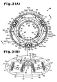
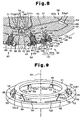
- Fig. 2 is a perspective view of the optical element holding device 38
- Fig. 3A is a plan view of the optical element holding device 38
- Fig. 3B is a partially enlarged view of Fig. 3A
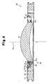
- Fig. 4 is a cross-sectional view taken along line 4-4 in Fig. 3A
- the optical element 37 is made of glass material having strength that is greater than or equal to a predetermined value such as synthetic quart or fluorite.
- a flange 37a is formed on the peripheral portion of the optical element 37.
- the optical element holding device 38 includes a frame member 41 having a fastening portion 40 connected to another optical element holding device (barrel module), and a lens frame body 43 for holding the optical element 37 with a support member 42.
- the frame member 41 and the lens frame body 43 are both substantially annular.
- the lens frame body 43 is provided in the inner side of the frame member 41 and fixed to a step 44 formed on the inner circumferential surface of the frame member 41 by a plurality of bolts 45.
- three support members 42 are arranged at equiangular intervals on the lens frame body 43.
- a known optical element support member for example, the optical element holding device disclosed in Japanese Laid-Open Patent Publication No. 2002-162549 is used as the support member 42.
- the support member 42 includes a base member 46 (refer to Fig. 4 ) and a clamp member 47, and the flange 37a of the optical element 37 is held between the base member 46 and the clamp member 47.
- the base member 46 has a flexure structure for absorbing factors transmitted from the external part of the support member 42 to the support member 42 and affecting the state of the optical surface of the optical element 37 (e.g., microscopic surface roughness and surface undulation of a main body of the exposure apparatus 31 and fastening portion 40 of the frame member 41).
- the optical surface of the optical element 37 is maintained in a satisfactory state with the optical element 37 attached to the external device by the support member 42, the lens frame body 43, and the frame member 41 due to such flexure structure.
- the frame member 41 includes an inner ring 51 functioning as a holding member and an inner frame member, an outer ring 52, arms 53a1, 53a2, 53b1, 53b2, 53c1, and 53c2 functioning as a first link portion, levers 54 functioning as a second link portion, and supporting links 55 functioning as a third link portion.
- the arms 53a1, 53a2, 53b1, 53b2, 53c1, 53c2 and the levers 54 form an orientation adjustment mechanism 50 for adjusting the orientation of the inner ring 51 to adjust the orientation of the optical element 37.
- the inner ring 51, the outer ring 52, the arms 53a1, 53a2, 53b1, 53b2, 53c1, 53c2, the lever 54, and the supporting link 55 are formed on the frame member 41, which is a single structure (rigid body) formed through wire cut and electrical discharge machining.
- the inner ring 51 and the outer ring 52 are connected so as to be relatively movable by the arms 53a1, 53a2, 53b1, 53b2, 53c1, and 53c2 and the lever 54 or by the arms 53a1, 53a2, 53b1, 53b2, 53c1, and 53c2, the lever 54, and the supporting link 55.
- the pair of arms 53a1 and arm 53a2 function as a first link mechanism 53a
- the pair of arms 53b1 and arm 53b2 function as a second link mechanism 53b
- the pair of arms 53c1 and 53c2 function as a third link mechanism 53c.
- the first to the third link mechanisms 53a, 53b, and 53c are arranged at equiangular intervals along a circle of which the center is the optical axis AX of the optical element 37.
- the first link mechanism 53a will now be described with reference to Fig. 5 to Fig. 7 .
- the second and the third link mechanisms 53b and 53c have the same structure as the first link mechanism 53a.
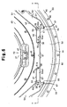
- Fig. 5 is an enlarged view showing the vicinity of the pair of arms 53a1 and 53a2.
- Fig. 6 is an enlarged view of the arm 53a1.
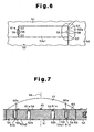
- Fig. 7 is a cross-sectional view taken along line 7-7 of Fig. 5 .
- an element side pivot (first neck portion) 58 and a frame side pivot (second neck portion) 59 are respectively formed on a first end portion and a second end portion of each arm 53a1 and 53a2.
- Each pivot 58 and 59 is formed between a pair of through holes 56.
- each arm 53a1 and 53a2 is defined between the pair of through holes 56 and slits 57 extending from each through hole 56.
- the element side pivots 58 rotatably connect the associated arms 53a1 and 53a2 to the inner ring 51.
- the frame side pivots 59 rotatably connect the associated arms 53a1 and 53a2 to the levers 54.
- the frame member 41 includes a first surface 60 and a second surface 63 that are substantially orthogonal to the optical axis AX of the optical element 37.
- the first surface 60 includes a small recess 61a having a center aligned with the element side pivot 58, and a large recess (cutout portion) 62a having a center aligned with the frame side pivot 59.
- the large recess 62a has an opening that is larger than the opening of the small recess 61a and is deeper than the small recess 61a.
- the small recess 61a and the large recess 62a are formed by cutting out the first surface 60 through, for example, electrical discharge machining.
- the second surface 63 is parallel to the first surface 60 and is located opposite to the first surface 60.
- the second surface 63 includes a large recess 62b having a center aligned with the element side pivot 58 and a small recess 61b having a center aligned with the frame side pivot 59.
- the small recess 61b and the large recess 62b are respectively similar to the small recess 61a and the large recess 62a.
- each arm 53a1, 53a2 is equivalent to a rigid body arranged in a state inclined with respect to the optical axis AX of the optical element 37 within the range of thickness of the frame member 41.
- a hypothetical line connecting the element side pivot 58 and the frame side pivot 59 lies along a tangential plane (first plane) Pt including a tangential line of a circle of which the center is the optical axis AX.
- the hypothetical line of the arm 53a1 and the hypothetical line of the arm 53a2 are substantially symmetric with respect to a plane, which includes the optical axis AX of the optical element 37 and which is orthogonal to the tangential plane Pt, that is, a radial plane (second plane) Pr extending in the radial direction of the optical element 37.
- the levers 54 are each elongated and arranged between the first to the third link mechanisms 53a, 53b, 53c.
- a portion close to the inner circumferential side of the frame member 41 at the first end portion of the lever 54 is rotatably connected to the second end portion of each arm 53a1, 53a2 by the frame side pivot 59.
- a portion close to the outer circumferential side of the frame member 41 at the first end portion of the lever 54 is rotatably connected to the outer ring 53 by a supporting point pivot 66.
- the supporting point pivot 66 is formed between a pair of through holes 67 extending through the frame member 41 in the thicknesswise direction.
- the lever 54 is defined between the pair of through holes 67 and a pair of slits 68 extending from each through hole 67 and through the frame member 41 in the thicknesswise direction.
- the supporting point pivot 66 is provided so that the line connecting the supporting point pivot 66 and the frame side pivot 59 is orthogonal to the line connecting the frame side pivot 59 and the element side pivot 58.
- a supporting link 55 is provided in the vicinity of the second end portion of the lever 54.
- the supporting link 55 includes a first supporting link 69 and a second supporting link 70.
- the first and second supporting links 69, 70 are defined between a pair of through holes 71 extending through the frame member 41 in the thicknesswise direction and a pair of slits 72 extending from each through hole 71 and through the frame member 41 in the thicknesswise direction.
- the first end portion of the first supporting link 69 is rotatably connected to the vicinity of the second end portion of the lever 54 by a distal end side supporting pivot 73.
- the second end portion of the first supporting link 69 is rotatably connected to the first end portion of the second supporting link 70 by an intermediate supporting pivot 74.
- the intermediate supporting pivot 74 connects the second supporting link 70 and the first supporting link 69 at right angle.
- the distal end side supporting pivot 73, the intermediate supporting pivot 74, and the supporting pivot 66 of the lever 54 are arranged along a straight line.
- the second end portion of the second supporting link 70 is rotatably connected to the frame member 41 by a basal end side supporting pivot 75.
- the basal end side supporting pivot 75 is thicker than the distal end side supporting pivot 73 and the intermediate supporting pivot 74.
- Each supporting pivot 73, 74, 75 is formed between the through holes 71.
- a spring accommodating recess 76 is arranged in the vicinity of the second end portion of the lever 54 at the first surface 60 of the frame member 41.
- a pair of biasing springs 77 are provided in each spring accommodating recess 76.
- Each biasing spring 77 extends between the lever 54 and the outer ring 52 and biases the second end portion of the lever 54 towards the outer ring 52.
- the spring accommodating recess 76 and the pair of biasing springs 77 may also be arranged on the second surface 63 of the frame member 41.
- a plurality of bolt holes 80 used to fasten other barrel modules 39a are formed in the fastening portion 40 of the outer ring 52.
- An annular groove 81 extending along the fastening portion 40 is formed in the first surface 60 of the frame member 41.
- An O-ring (not shown) is received in the annular groove 81 to hermetically seal the interior of the barrel 39 from the exterior with the plurality of barrel modules 39a in a stacked state.
- a displacement module 82 functioning as a displacement member is accommodated in a displacement module attachment hole 83 formed in a direction substantially the same as the biasing direction of the biasing spring 77 in the side surface of the outer ring 52.
- the displacement module 82 includes a displacement rod 84 serving as a contact portion, an adjustment washer 85, an adjustment button 86, and an adjustment base plate 87. At least one of the adjustment washers 85 or the adjustment button 86 functions as a changing member.
- a displacement rod housing 89 is fitted into the displacement module attachment hole 83.
- the displacement rod 84 is movably inserted into the displacement rod housing 89.
- the displacement rod 84 has a substantially circular cylinder shape having flat end surfaces. One of the end surfaces of the displacement rod 84 contacts a spherical boss 92 fixed to the vicinity of the second end portion of the lever 54 with a stud bolt 91.
- the supporting bolt 93 extends through the middle of the adjustment base plate 87 to be fastened.
- the adjustment washer 85 and the adjustment button 86 are attached to the distal end of the supporting bolt 93.
- the distal end of the adjustment button 86 has a substantially spherical shape.
- the adjustment washer 85 is selected from a plurality of washers having thicknesses different from each other by 1 ⁇ m
- the adjustment button 86 is selected from a plurality of buttons having heights different from each other by 0.1 mm.
- the displacement amount of the displacement rod 84 is changed in accordance with the thickness of the adjustment washer 85 and the height of the adjustment button 86. That is, the displacement force (driving force F) applied to the lever 54 by the displacement rod 84 may be changed by selecting an adjustment washer 85 from different thicknesses and an adjustment button 86 from different heights.
- the displacement force which is a force generated when the attached adjustment washer 85 and adjustment button 86 are exchanged with a different adjustment washer 85 and adjustment button 86, is referred to as "driving force F".
- the adjustment button 86 and the adjustment washer 85 are respectively used for rough adjustment and fine adjustment of the driving force F.
- a jack up module 97 serving as an adjustment member is accommodated in a jack up module attachment hole 98 formed adjacent to the displacement module attachment hole 83 in the side surface of the outer ring 52.
- the jack up module 97 includes a jack up rod 99, a jack up housing 100, and a position adjustment screw 101.
- the jack up rod 99 is movably inserted into the jack up module attachment hole 98.
- the interior and the exterior of the frame member 41 is maintained in an air tight manner by the O-ring arranged between the jack up rod 99 and the jack up module attachment 98.
- the distal end of the jack up rod 99 is spherical, and the other end is planar (hereinafter referred to as basal end surface).
- the distal end of the jack up rod 99 contacts the side face of the lever 54 when the jack up rod 99 is moved towards the lever 54.
- a threaded hole 103 extending along the longitudinal axis of the jack up rod 99 is formed in the basal end surface of the jack up rod 99.
- a rotation restriction portion 104 for restricting rotation of the jack up rod 99 by engaging with the inner circumferential surface of the jack up module attachment hole 98 is formed on the other end of the jack up rod 99.
- the jack up housing 100 includes a holding plate 105, for holding the position adjustment screw 101 mated with the threaded hole 103 of the jack up rod 99, and a stop plate 106 for preventing the position adjustment screw 101 from falling out.
- a stepped accommodating hole 107 is formed in the central portion of the holding plate 105.
- the position adjustment screw 101 is rotatably inserted into the holding plate 105 so that the head 101a of the position adjustment screw 101 is engaged with a stepped portion 108 of the accommodating hole 107.
- a wrench hole 101b for receiving a jig, such as a hexagonal wrench, is formed in the head 101a of the position adjustment screw 101.
- a through hole 110 formed in the central portion of the stop plate 106 enables the jig to be inserted into the wrench hole 101b of the position adjustment screw 101 in a state in which the stop plate 106 and the holding plate 105 are joined and fixed to the frame member 41 by the bolt 109.
- the diameter of the opening of the through hole 110 is smaller than the diameter of the head 101a of the position adjustment screw 101. The position adjustment screw 101 is thus prevented from falling out by fixing the stop plate 106, which is joined with the holding plate 105, to the frame member 41.
- Fig. 9 the arms 53a1, 53a2, 53b1, 53b2, 53c1, 53c2 are shown as six rigid shafts, and the inner ring 51, the outer ring 52, and each lever 54 are shown in a simple form.
- Fig. 10 is an enlarged view of the first link mechanism 53a of Fig. 9 .
- each arm 53a1, 53a2, 53b1, 53b2, 53c1, 53c2 is rotatably connected to the inner ring 51 and rotatably connected to the first end portion of each lever 54. Further, the lever 54 is rotatably connected to the outer ring 52.
- the orientation of the inner ring 51 is adjustable with six degrees of freedom with respect to the outer ring 52.
- the inner ring 51 is kinematically supported with respect to the outer ring 52 by the arms 53a1, 53a2, 53b1, 53b2, 53c1, 53c2 and the levers 54.
- each arm 53a1, 53a2, 53b1, 53b2, 53c1, 53c2 is connected to each lever 54.
- the lever 54 is displaced.
- the displacement is conveyed to the inner ring 51 without any backlash or hysteresis.
- the orientation of the inner ring 51 is changed without any backlash or hysteresis due to the cooperating action of the six arms 53a1, 53a2, 53b1, 53b2, 53c1, 53c2.
- the orientation of the inner ring 51 is changed in accordance with the change in the inclination angle of each arm 53a1, 53a2, 53b1, 53b2, 53c1, 53c2.
- the orientation of the inner ring 51 may be calculated from the displacement amount of each arm 53a1, 53a2, 53b1, 53b2, 53c1, 53c2.
- the optical element 37 is held in the inner ring 51 by the support members 42 of the optical element holding device 38.
- the orientation of the optical element 37 is adjusted by adjusting the orientation of the inner ring 51.
- Adjusting the orientation of the inner ring 51 without involving backlash or hysteresis is essential in adjusting the orientation of the optical element 37 with high accuracy.
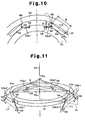
- FIG. 11 schematic shows the inner ring 51 and the arms 53a1, 53a2, 53b1, 53b2, 53c1, 53c2.
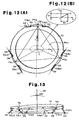
- Fig. 12A is a plan view of Fig. 11 .
- the three link mechanisms 53a, 53b, 53c formed by six arms 53a1, 53a2, 53b1, 53b2, 53c1, 53c2 are arranged at equiangular intervals along a circle of which the center is the optical axis AX of the optical element 37.
- each pair of arms 53a1 and 53a2, 53b1 and 53b2, and 53c1 and 53c2 is parallel to the optical axis AX and arranged along a tangential plane Pt including the tangential line of the circle.
- each of the arms 53a1 and 53a2, 53b1 and 53b2, and 53c1 and 53c2 are not arranged at a skew position and the extended line of the arm (53b1, 53c1) and the extended line of the arm 53a2 (53b2, 53c2) always intersect in the associated tangential plane Pt. Further, each of the arms 53a1 and 53a2, 53b1 and 53b2, and 53c1 and 53c2 are symmetric with respect to the radial plane Pr including the optical axis AX and are orthogonal to the tangential plane Pt.
- an intersection line of a plane, which extends through the frame side pivot 59 of the two arms 53a1 and 53a2 (53b1 and 53b2, 53c1 and 53c2) and which is orthogonal to the optical axis AX of the optical element 37, and the tangential plane Pt is defined as a drive line L1.
- the inner ring 51 is displaced by moving each frame side pivot 59 along the drive line L1.
- a first hypothetical pivot PVa The intersection of the extended lines of both arms 53b1, 53b2 of the second link mechanism is assumed as a second hypothetical pivot PVb.
- the intersection of the extended lines of both arms 53c1, 53c2 of the third link mechanism is assumed as a third hypothetical pivot PVc.
- the plane including the three hypothetical pivots PVA, PVb, PVc is referred to as a pivotal plane Ppv.
- the pivotal plane Ppv is orthogonal to the optical axis AX of the optical element 37 when it does not displace each frame side pivot 59 of each arm 53a1, 53a2, 53b1, 53b2, 53c1, 53c2 (reference state).
- the center of a circle extending through the three hypothetical pivots PVa, PVb, PVc on the pivotal plane Ppv is referred to as an observation point C.
- the observation point C lies on the optical axis AX of the optical element 37 in the reference state.
- Figs. 12A, 12B show the reference state.
- the position of the observation point C in the reference state is referred to as the origin point.
- the direction of the normal line of the tangential plane Pt corresponding to the first link mechanism 53a is the Y-axis.
- the direction from the origin towards the tangential plane Pt is the positive direction.
- the X-axis is orthogonal to the Y-axis on the pivotal plane Ppv.
- the optical axis Ax of the optical element 37 is the Z-axis.
- the upward direction in the Z-axis is the positive direction.
- the six degrees of freedom for orientation adjustment of the inner ring 51 with respect to the outer ring 52 includes three degrees of freedom for parallel movement (shift movement) along each axis, and three degrees of freedom of rotation about each axis in the orthogonal coordinate system.
- the rotation about the Z-axis is rotation of the pivotal plane Ppv
- the rotation about the X-axis and the rotation about the Y-axis are related to the tilt of the pivotal plane Ppv.
- the orientation of the inner ring 51 changes and the observation point C is displaced.
- the displacement component of the observation point C along each axis direction is dx, dy, dz
- the orientation adjustment of the optical element 37 for performing aberration control of the projection optical system 35 is performed by displacing each optical element 37 in an extremely fine manner.
- the change in orientation of the inner ring 51 may be linearly decomposing into rotation amounts d ⁇ x, d ⁇ y, d ⁇ z about each axis of X, Y, Z.
- the symbol of the rotation about each coordinate axis complies with the right hand corkscrew rule with respect to the positive direction of each coordinate axis.
- the superscript T indicates that a 6 ⁇ 1 matrix is transposed so as to be written in one line.
- each frame side pivot 59 that occurs with the change of inclination angle of each arm is only movable in a straight line along the drive line L1 and the degree of freedom is 1.
- the input displacement vector ⁇ p with respect to the inner ring 51 is expressed as equation (2).
- the orientation change vector ⁇ I of the inner ring 51 and the input displacement vector ⁇ p corresponds at 1:1.
- the relationship between the input displacement vector ⁇ p and the orientation change vector ⁇ I is a linear transformation.
- the transformation matrix is A (6x6 matrix)
- the orientation change vector ⁇ I is expressed as equation (3).
- the transformation matrix A is expressed as equation (4).
- A a ⁇ 1 a ⁇ 2 R ⁇ a ⁇ 1 R ⁇ a ⁇ 2 R 2 ⁇ a ⁇ 1 R 2 ⁇ a ⁇ 2
- a ⁇ 1 - 1 3 0 1 6 tan ⁇ 1 3 ⁇ r tan ⁇ 0 1 6 r T
- a ⁇ 2 1 3 0 1 6 tan ⁇ 1 3 r tan ⁇ 0 - 1 6 r T
- R is a 120° rotation matrix about the Z-axis
- ⁇ is the angle formed by each arm 53a1, 53a2, 53b1, 53b2, 53c1, 53c2 and the drive line L1
- r is the radius of the arrangement circle of the hypothetical pivot PVa, PVb, PVc of which the center is the optical axis AX of the optical element 37.
- the orientation adjustment precision, the resolution, and the movable range of the inner ring 51 are optimized by appropriately defining the angle
- Equation (3) may be transformed to equation (7).
- ⁇ ⁇ p ⁇ A - 1 ⁇ ⁇ ⁇ I ⁇
- the driving amount of each frame side pivot 59 that is, the input displacement vector ⁇ p for accomplishing the orientation change vector ⁇ I of the optical element 37 determined in terms of optical adjustment of the projection optical system 35 is obtained by a simple calculation.
- levers 54 are each connected to the inner side of the outer ring 52 by a supporting point pivot 66.
- Each lever 54 is rotatable in the plane orthogonal to the optical axis AX of the optical element 37 about the associated supporting point pivot 66.
- the associated arms 53a1, 53a2, 53b1, 53b2, 53c1, 53c2 are connected to the one end portion of each lever 54 that is connected to the supporting point pivot 66 by the frame side pivot 59.
- the lever 54 is arranged so that the frame side pivot 59 is displaced within the associated tangential plane Pt.
- the end portion different from the one end portion connected to the supporting point pivot 66 in the longitudinal direction of the lever 54 is a force point PF of the lever 54.
- the lever 54 is rotated about the supporting point pivot 66.
- the lever 54 has a geometric plane shape equivalent to a trapezoid.
- the oblique line 111 between the supporting point pivot 66 and the frame side pivot 59 is substantially perpendicular to the tangential plane Pt.
- the length of the side 112 on the outer ring 52 side of the lever 54 that is, the distance between the supporting point pivot 66 and the power force PF is represented by ⁇
- the length of the oblique line 111 is represented by ⁇ .
- the driving displacement ⁇ L applied to the force point PF is always reduced by ⁇ / ⁇ times and conveyed due to the shape of the lever 54. Since the externally applied displacement is reduced and conveyed to each arm 53a1, 53a2, 53b1, 53b2, 53c1, 53c2 and the inner ring 51, the orientation adjustment of the optical element 37 is performed with high accuracy and high resolution.
- the lever 54 converts the displacement in the radial direction of the optical element 37 by the drive force F to displacement along the tangential line direction of the optical element 37.
- the lever 54 is supported by the outer ring 52 only with the supporting point pivot 66, the supporting rigidity may become insufficient.
- the other end portion of the lever 54 opposite the one end portion connected to the supporting point pivot 66 in the longitudinal direction of the lever 54 is supported by the outer ring 52 with the supporting link 55.
- the lever 54 is supported at two sides by the outer ring 52 and thus stably supported with sufficient rigidity.
- the first supporting link 69 of the supporting link 55 is arranged along an extension of the line connecting the supporting point pivot 66 and the distal end side supporting pivot 73.
- the jig is engaged with the wrench hole of the position adjustment screw 101 of the jack up module 97.
- the jig is used to rotate the position adjustment screw 101 until the distal end of the jack up rod 99 contacts the lever 54.
- the adjustment base plate 87 in the displacement module 82 is then removed from the frame member 41. This eliminates the pressing force applied from the displacement rod 84 to the spherical boss 92 and releases the driving displacement ⁇ L of the force point PF of the lever 54.
- the biasing force of the biasing spring 77 rotates the lever 54 toward the outer ring 52. However, the lever 54 is in contact with the jack up rod 99.
- the lever 54 is arranged at a predetermined position without contacting the inner circumferential surface of the outer ring 52.
- the adjustment washer 85 and the adjustment button 86 are removed from the frame member 41 along with the adjustment base plate 87.
- the displacement rod 84 is kept in the displacement module attachment hole 83 by the displacement rod housing 89 even if the adjustment washer 85 and the adjustment button 86 are removed.
- the O-rings 88, 90 are respectively arranged between the displacement rod 84 and the displacement rod housing 89 and between the displacement rod housing 89 and the inner circumferential surface of the displacement module attachment hole 83. This keeps the optical element holding device 38 hermetically sealed even if the adjustment washer 85 and the adjustment button 86 are removed.
- the adjustment washer 85 and the adjustment button 86 are exchanged with those having the appropriate thickness, and the adjustment base plate 87 is attached to the frame member 41.
- the position of the displacement rod 84 in the displacement module attachment hole 83 is changed in accordance with the thickness of the adjustment washer 85 and the adjustment button 86.
- the displacement of the displacement rod 84 changes the position of the spherical boss 92, changes the pressing force with respect to the force point PF of the lever 54, and the driving displacement ⁇ L is applied to the lever 54.
- the lever 54 is rotated by the driving displacement ⁇ L, the frame side pivot 59 of each arm 53a1, 53a2, 53b1, 53b2, 53c1, 53c2 is displaced along the associated drive line L1.
- the driving displacement ⁇ L applied by the displacement module 82 is reduced by a predetermined scale and conveyed to each frame side pivot 59.
- the displacement of each arm 53a1, 53a2, 53b1, 53b2, 53c1, 53c2 is synthesized in the inner ring 51 by each element side pivot 58. For example, this changes the orientation of the inner ring 51 from the orientation in which the upper surface shown by broken lines in Fig. 12A and Fig. 13 lies along a plane orthogonal to the optical axis of the optical element 37 to the orientation in which the upper surface shown by solid lines is inclined with respect to the optical axis AX.
- the orientation of the optical element 37 is adjusted as the orientation of the inner ring 51 changes.
- the orientation change of the inner ring 51 will be briefly be described in relation with the displacement of each arm 53a1, 53a2, 53b1, 53b2, 53c1, 53c2.
- each of the pairs of arms 53a1 and 53a2, 53b1 and 53b2, 53c1 and 53c2 is displaced by the same displacement amount so as to move closer to each other in each of the link mechanisms 53a, 53b, 53c, the inner ring 51 is moved upward in a parallel manner along the optical axis AX of the optical element 37 by the element side pivot 58.
- the inner ring 51 may be inclined at a desired angle with respect to the optical axis AX of the optical element 37 by the element side pivot 58.
- the optical element 37 may be adjusted to any orientation by respectively setting the displacement amount of each frame side pivot 59 of the six arms 53a1, 53a2, 53b1, 53b2, 53c1, 53c2.
- the displacement amount of each frame side pivot 59 is determined in accordance with the driving displacement ⁇ L in the displacement module 82, which engages the frame side pivot 59 with the lever 54.
- the driving displacement ⁇ L is easily adjusted by changing the thickness of the adjustment washer 85 and the adjustment button 86 included in the displacement module 82.
- the present embodiment has the advantages described below.
- each arm 53a1, 53a2, 53b1, 53b2, 53c1, 53c2 is arranged on the tangential plane Pt of a circle of which the center is the optical axis AX of the optical element 37, and the driving line L1 of the frame side pivot 59 is set on the tangential plane Pt.
- each arm 53a1, 53a2, 53b1, 53b2, 53c1, 53c2 may be arranged at a position separated from the tangential plane Pt.
- the first surface 60 and the second surface 63 side in the tangential plane Pt may be brought closer to the optical axis AX of the optical element 37 and arranged on an inclined plane.
- the optical element 37 when holding the optical element 37 of small diameter, the optical element 37 is held with a small lens frame body 43 without using a large lens frame body 43. Consequently, increase in weight around the driven optical element 37 is avoided, and orientation adjustment of the optical element 37 is facilitated.
- the driving line L1 of the frame side pivot 59 may be separated from the tangential plane Pt.
- the arms 53a1, 53a2, 53b1, 53b2, 53c1, 53c2 do not have to be in pairs and at least one in each pair may be arranged independently from the other arm.
- two arms 53a1 and 53a2 (53b1 and 53b2, 53c1 and 53c) of each link mechanism 53a, 53b, 53c are symmetric with respect to the radial plane Pr.
- the two arms 53a1 and 53a2 (53b1 and 53b2, 53c1 and 53c) may be asymmetric with respect to the radial plane Pr.
- the link mechanisms 53a, 53b, 53c do not have to be arranged at equiangular intervals along a circle of which the center is the optical axis AX of the optical element 37. It is only required that the optical element holding device 38 have a mechanism capable of adjusting the orientation of the holding optical element 37 with six degrees of freedom. More specifically, it is only required that the optical element holding device includes six arms rotatably connected to the frame member 41 on the fixed portion side and the support member 42 for supporting the optical element 37, and that the six arms be arranged so that the extensions of each arm do not intersect at one point.
- each line there are two lines, a line connecting the element side pivot 58 and the frame side pivot 59 of the two ends of each arm 53a1, 53a2, 53b1, 53b2, 53c1, 53c2 and a line connecting the frame side pivot 59 and the supporting point pivot 66 of one end of the lever 54.
- the element side pivot 58, the frame side pivot 59, and the supporting point pivot 66 are arranged so that the two lines are orthogonal to each other.
- each pivot 58, 59, 66 may be arranged so that the two lines are not orthogonal to each other.
- the driving force F applied to the force point PF of the lever 54 is reduced and conveyed to each arm 53a1, 53a2, 53b1, 53b2, 53c1, 53c2.
- the adjustment of the driving force F at the displacement module 82 is performed by selecting and exchanging appropriately ones of the plurality of adjustment washers 85 and adjustment buttons 86 and displacing the displacement rod 84.
- a micrometer may be used in the displacement module 82, and the displacement rod 84 may be displaced by moving the micrometer forward or backward. In such a case, the adjustment of the driving force F is facilitated and fine adjustment is also facilitated.
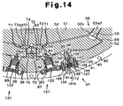
- an actuator such as a piezoelectric element 122 may be installed in the displacement module 121, and the displacement rod 84 may be displaced by the drive of the piezoelectric element 122.
- the orientation control of the optical element 37 may be carried out at a remote location. For example, if the orientation of the optical element 37 is controlled in accordance with the control signal generated based on the aberration information, the irradiation history of the optical element 37, change in the environment condition which the exposure apparatus 31 is arranged, change in the exposure condition such as the illuminating condition and the like obtained during the operation of the exposure apparatus 31, correction of aberration is carried out more finely and in real time. The exposure accuracy in the exposure apparatus 31 is improved, and throughput is improved by reduction of down time. Further, a fluid pressure actuator may be used instead of the piezoelectric element 122.
- a sensor for detecting the orientation of the optical element 37 may be used. In such a case, further accurate orientation control of the optical element 37 is performed.
- an optical window is arranged on the outer circumferential surface of the frame member 41, and a sensor of an optical encoder type or an electrostatic capacity type for reading a scale attached to the optical element 37 or the lens frame body 43 through the optical window with a head arranged outside the barrel 39 is preferable.
- cords connected to the sensor and substrate of the sensor and the like do not need to be arranged inside the barrel 39. This keeps the inside of the barrel 39 clean.
- the O-ring may be omitted, and the fastening portions 40 of the two frame members 41 may be directly fastened to each other.
- a gasket may be arranged between the joining surfaces of the fastening portions 40, and the joining portion of the fastening portion 40 may be covered with a cover.
- An O-ring may be arranged between the cover and the outer circumferential surface of the fastening portion 40.
- the lens frame body 43 may be omitted, and the first end portion of the arm 53a1, 53a2, 53b1, 53b2, 53c1, 53c2 may be directly connected to the support member 42 by the element side pivot 58.
- the first supporting link 69 and the second supporting link 70 may intersect at an angle smaller than 90 degrees or at an angle greater than 90 degrees. Further, the supporting link 55 may be omitted. An L-shaped plate spring and the like may be arranged in place of the supporting link 55. In this case, the plate spring is formed through wire cut and electrical discharge machining into a structure that is the same as the frame member 41. Further, in the preferred embodiment, the first supporting link 69 is arranged so as to extend along an extension of the line connecting the supporting point pivot 66 and the distal end side supporting pivot 73 of the two ends of the lever 54. However, the first supporting link 69 may be separated from the extension of the line.
- the O-rings 90, 88 are arranged between the outer circumferential surface of the displacement rod 84 in the displacement module 82 and the displacement rod housing 89, and between the outer circumferential surface of the displacement rod housing 89 and the inner circumferential surface of the displacement module attachment hole 83.
- a magnetic fluid seal and the like may be used in place of the O-rings 90, 88. This is particularly effective in a structure for controlling the orientation of the optical element 37 during the operation of the exposure apparatus 31 since the hysteresis factors are eliminated.
- the displacement rod 84 is accommodated in the displacement module attachment hole 83 of the frame member 41 in a state accommodated in the displacement rod housing 89.
- the displacement rod housing 89 may be omitted and the displacement rod 84 may be attached directly to the displacement module attachment hole 83.
- the driving force F is applied to the lever 54 by the movement (translational motion) in the radial direction of the optical element 37 of the displacement rod 84.
- the driving force may be applied to the lever 54 by rotating the displacement rod 84, moving the displacement rod 84 in the optical axis direction or other directions, or by rotating the displacement rod 84 in the circumferential direction of the frame member 41.
- the element side pivot 58 is defined between the small recess 61a from the first surface 60 and the large recess 62b from the second surface.
- the frame side pivot 59 is defined between the small recess 61b from the second surface 63 and the large recess 62a from the first surface 60.
- at least one of either the element side pivot 58 or the frame side pivot 59 may be defined between the small recesses 61a, 61b and a different small recess may be formed at the bottom of the large recess 62a, 62b.
- the large recess 62a, 62b are cut out and formed with a predetermined depth in the recess of the side in which the cut out amount of the first surface 60 or the second surface 63 of the frame member 41 is large.
- a different small recess 61a, 61b is then formed through electrical discharge machining from the bottom. This easily forms the small recesses 61a, 61b on both sides of each pivot 58, 59. Thus, even when forming small recesses 61a, 61b on both sides of each pivot 58, 59, the machining time may be reduced.
- a pair of small recesses 61a, 61b on both sides of the neck in each pivot 58, 59 are formed during the same cutting process. This prevents unpredictable distortion at each pivot 58, 59 from remaining. This further improves the accuracy of the orientation control of the optical element 37 at the optical element holding device 38.
- the optical element 37 is given as an example of a lens.
- the optical element 37 may be another type of optical element, such as a parallel flat plate, a mirror, a half-mirror and the like.
- the optical element holding device 38 of the present invention is not limited to the holding structure for the optical element 37 of the horizontal type as in the projection optical system 35 of the exposure apparatus 31 in the preferred embodiment, and may be embodied in a holding structure for an optical element in the illumination optical system 33 of the exposure apparatus 31 or a holding structure for the optical element 37 of the vertical type. Further, the present invention may be embodied in a structure for holding the optical element in an optical system of other optical machines such as a microscope, an interferometer and the like.
- An optical system of a contact exposure apparatus, in which the mask and the substrate are closely contacted and the pattern of the mask is exposed, and a proximity exposure apparatus, in which the mask and the substrate are located near each other and the pattern of the mask is exposed, may be applied as the exposure apparatus without using a projection optical system.
- the projection optical system it is not limited to a total refraction type and may be of a catadioptric type.
- the exposure apparatus of the present invention is not limited to the exposure apparatus of a reduction exposure type, and may be, for example, an exposure apparatus of the equal exposure type or the enlargement exposure type.
- the present invention may also be applied to an exposure apparatus for transferring a circuit pattern from a mother reticle to a glass substrate or a silicon wafer.
- transmissive reticle is used in the exposure apparatus using DUV (deep ultraviolet) or VUV (vacuum ultraviolet) light and the like, and quartz glass, quartz glass doped with fluorine, fluorite, magnesium fluoride or crystal and the like is used as the reticle substrate.
- the transmissive mask (stencil mask, membrane mask) is used, and silicon wafer or the like is used as the mask substrate.
- the present invention is not only applicable to the exposure apparatus used in manufacturing the semiconductor device, but also to an exposure apparatus used in manufacturing displays including liquid crystal display (LCD) and the like to transfer a device pattern onto the glass plate.
- the present invention is also applicable to an exposure apparatus used in manufacturing thin-film magnetic heads or the like and transferring the device pattern onto ceramic wafers or the like, and an exposure apparatus used in manufacturing imaging devices such as CCDs.
- the present invention is applicable to a scanning stepper for transferring the pattern of a mask to a substrate in a state in which the mask and the substrate are relatively movable and sequentially step-moving the substrate.
- the present invention is also applicable to a step-and-repeat type stepper for transferring the pattern of a mask in a state in which the mask and the substrate are stationary and sequentially step-moving the substrate.
- g-line (436 nm), i-line (365 nm), KrF excimer laser (248 nm), Kr 2 laser (146 nm), Ar 2 laser (126 nm) may be used as the light source of the exposure apparatus.
- the harmonic component wave in which the single wavelength laser light of infrared region or visible region oscillated from a DFB semiconductor laser or a fiber laser may be amplified with fiber amplifier doped with, for example, erbium (or both erbium and ytterbium), and wave-converted to ultraviolet light using a non-linear optical crystal may be used.
- the exposure apparatus 31 of the embodiment is manufactured in the following way. At least some of the optical element 37 of a plurality of lenses or mirrors etc. forming the illumination optical system 33 and the projection optical system 35 is held by the optical element holding device 38 of the preferred embodiment or a modification, the illumination optical system 33 and the projection optical system 35 are incorporated in the main body of the exposure apparatus 31, and then optical adjustment is performed. Subsequently, the wafer stage 36 (also reticle stage 34 in case of scan type exposure apparatus) including many mechanical components is attached to the main body of the exposure apparatus 31 and wires are connected. A gas supply pipe for supplying gas is then connected to the optical path of the exposure light and total adjustment (electronic adjustment, checking of operations etc.) is performed.
- Each component configuring the optical element holding device 38 is assembled after eliminating impurities such as machining oil or metal substances through ultrasonic cleaning.
- the manufacturing of the exposure apparatus 31 is desirably performed in a clean room in which temperature, moisture, and air pressure are controlled and cleanliness is adjusted.
- Fluorite and quartz are given as examples of the glass material in the preferred embodiment.
- the optical element holding device 38 of the embodiment may be applied even when using improved quartz such as crystal of lithium fluoride, magnesium fluoride, strontium fluoride, lithium-calcium-aluminum-fluoride, lithium-strontium-aluminum-fluoride and the like, or glass fluoride including zirconium-barium-lanthanum-aluminum, quartz glass doped with fluoride, quartz glass doped with hydrogen in addition to fluoride, quartz glass containing OH-base, and quartz glass containing OH-base in addition to fluoride.
- improved quartz such as crystal of lithium fluoride, magnesium fluoride, strontium fluoride, lithium-calcium-aluminum-fluoride, lithium-strontium-aluminum-fluoride and the like, or glass fluoride including zirconium-barium-lanthanum-aluminum, quartz glass doped with fluoride, quartz glass do
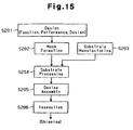
- Fig. 15 is a flowchart showing a manufacturing example for a device (semiconductor device such as an IC or LSI, liquid crystal display device, imaging device, CCD etc.), a thin-film magnetic head, a micro-machine etc.
- a device semiconductor device such as an IC or LSI, liquid crystal display device, imaging device, CCD etc.
- the function and performance design e.g., circuit design of semiconductor device
- step S201 design step
- pattern design for realizing the function is performed.
- step S202 mask formation step
- a mask reticle Rt etc.
- step S203 substrate manufacturing step
- the substrate wafer W when silicon material is used
- materials such as silicon, glass plate etc.
- step S204 substrate processing step
- step S205 device assembly step
- step S205 includes steps such as a dicing step, a bonding step, and a packaging step (chip enclosure etc.) that are performed if necessary.
- step S206 inspection step
- inspections such as an operation check test, a durability test and the like, are performed on the device formed in step S205.
- the device is then completed after the above steps and shipped out of the factory.
- Fig. 16 shows one example of a detailed flow of step S204 in Fig. 15 .
- the surface of the wafer W is oxidized in step S211 (oxidization step).
- step S212 CVD step
- step S213 electrode formation step
- step S214 ion implantation step
- ions are implanted into the wafer W.
- steps S211-S214 define a pre-processing step for each stage of the wafer process and are selected and executed in accordance with the necessary process in each stage.
- step S215 a photosensitive agent is applied to the wafer W in step S215 (resist formation step).
- step S216 exposing step
- step S216 exposing step
- step S216 exposing step
- step S217 developing step
- step S218 etching step
- step S219 resist removal step
- the pre-processing steps and the post-processing steps are repeatedly performed to form multiple circuit patterns on the wafer W.
- the method for manufacturing the device of the present embodiment that is described above enables the above described exposure apparatus 31 to be used in the exposure step (step S216) and improve resolution with the exposure light EL of vacuum ultraviolet region. Further, exposure amount control is performed with high accuracy. Consequently, devices having high integration with a minimum line width of about 0.1 ⁇ m are produced at a satisfactory yield.
Landscapes
- Physics & Mathematics (AREA)
- General Physics & Mathematics (AREA)
- Optics & Photonics (AREA)
- Health & Medical Sciences (AREA)
- Engineering & Computer Science (AREA)
- Environmental & Geological Engineering (AREA)
- Epidemiology (AREA)
- Public Health (AREA)
- Exposure And Positioning Against Photoresist Photosensitive Materials (AREA)
- Lens Barrels (AREA)
- Exposure Of Semiconductors, Excluding Electron Or Ion Beam Exposure (AREA)
- Formation Of Various Coating Films On Cathode Ray Tubes And Lamps (AREA)
- Eyeglasses (AREA)
- Mechanical Optical Scanning Systems (AREA)
- Mounting And Adjusting Of Optical Elements (AREA)
Abstract
Description
- The present invention relates to an optical element holding device for holding an optical element, a barrel incorporating the holding device, an exposure apparatus, and a method for manufacturing a device.
-
Fig. 17 and Fig. 18 show an optical element holding device incorporated in an exposure apparatus, which is used during a lithography step of a manufacturing process for a semiconductor device, a liquid crystal display device, an imaging device, a thin-film magnetic head, a reticle, a photomask, and the like. The conventional optical element holding device includes anannular frame body 302 and threeclamp members 306. Three seats (projections) 304 for supporting anoptical element 301, such as a lens, are formed at equiangular intervals on the inner circumferential surface of theframe body 302. Three threadedholes 305 are formed in the upper surface of theframe body 302 at positions corresponding to the threeseats 304. Theclamp members 306 are attached to the threadedholes 305 withbolts 307. - The
bolts 307 are fastened to hold the periphery 301a of theoptical element 301 between theclamp members 306 and theseats 304. - Due to increasing integration of a semiconductor device, there is a demand for an exposure apparatus enabling exposure of finer patterns. More specifically, there is a demand for an exposure apparatus provided with a projection optical system having an extremely small wave aberration or distortion. To satisfy such a demand, the optical axis of the
optical element 301 must be accurately positioned when installing theoptical element 301 in the projection optical system. - Conventionally, the
optical element 301 is positioned in the following manner. First, theoptical element 301 is held on theframe body 302. The outer circumferential surface and the bottom surface of theframe body 302 are then respectively engaged with an inner wall and a receiving portion of a barrel to attach theframe body 302 to the barrel. This positions the optical axis of theoptical element 301. The degree of freedom is extremely small and exists when attaching theframe body 302 to the barrel, and the task of attaching theframe body 302 to the barrel is a troublesome task that requires much care. - The
optical element 301 is sandwiched between theclamp members 306 and theseats 304 and held by theframe body 302 in a state with subtle degree of freedom. When theframe body 302 is attached to the barrel in a slightly tilted state, theframe body 302 may be subjected to excessive load and may be distorted. When theframe body 302 is distorted, unpredictable stress caused by such distortion may act on theoptical element 301 and lower the accuracy of the optical surface of theoptical element 301. - A recent exposure apparatus for manufacturing semiconductors uses exposure light of shorter wavelengths to expose finer patterns with high accuracy. For instance, ultraviolet light of an i line (λ=365nm), far ultraviolet light of a KrF excimer laser (λ=248nm), ArF excimer laser (λ=193nm), and F2 laser (λ=157nm) of short wavelengths are used. In the exposure apparatus using exposure light having a short wavelength as described above, position adjustment of the optical element in the barrel is necessary to maximize the imaging capability with the shorter wavelength of the exposure light. For instance, fine adjustment of the orientation of the
optical element 301 in the optical element holding device with respect to theframe body 302 is required. - It is an object of the present invention to provide an optical element holding device facilitating accurate positioning of an optical element, while enabling fine orientation adjustment of the optical element. Another object of the present invention is to provide an exposure apparatus that improves the exposure accuracy. A further object of the present invention is to provide a method for manufacturing a device that enable highly integrated devices to be manufactured with high yield.
- To achieve the above object, one aspect of the present invention provides an optical element holding device as defined in
claim 1. An optical element holding device comprising: a frame member; a holding member provided at an inner side of the frame member, for holding an optical element; and an orientation adjustment mechanism for adjusting orientation of the optical element held by the holding member with respect to the frame member with six degrees of freedom wherein ; the orientation adjustment mechanism includes: a plurality of link portions connecting the frame member and the holding member; a displacement member which is attached to an opening formed in a side surface of the frame member and providing displacement force to the holding member via the plurality of link portions; and a seal member is arranged between an inside surface of the opening and an outside surface of the displacement member. -
-
Fig. 1 is a schematic diagram of an exposure apparatus according to one embodiment of the present invention; -
Fig. 2 is a perspective view showing an optical element holding device ofFig. 1 ; -
Fig. 3A is a plan view showing the optical element holding device ofFig. 1 ; -
Fig. 3B is a partially enlarged view ofFig. 3A ; -
Fig. 4 is a cross-sectional view taken along line 4-4 inFig. 3 ; -
Fig. 5 is an enlarged plan view showing an arm of a frame member ofFig. 2 ; -
Fig. 6 is a partially enlarged view ofFig. 5 ; -
Fig. 7 is a cross-sectional view taken along line 7-7 inFig. 5 ; -
Fig. 8 is a cross-sectional view of the frame member ofFig. 2 taken along a plane orthogonal to an optical axis of the optical element; -
Fig. 9 is a schematic perspective view of each link mechanism ofFig. 2 ; -
Fig. 10 is an enlarged plan view showing a first link mechanism ofFig. 9 ; -
Fig. 11 is a schematic perspective view of an inner ring and arm ofFig. 2 ; -
Fig. 12A is a schematic plan view of the inner ring and arm ofFig. 2 ; -
Fig. 12B is a partially enlarged view ofFig. 12A ; -
Fig. 13 is a schematic side view of the inner ring and arm ofFig. 2 ; -
Fig. 14 is a cross-sectional view showing a modification of a displacement module; -
Fig. 15 is a flowchart showing the manufacturing procedures of a device; -
Fig. 16 is a flowchart showing a substrate processing step ofFig. 15 in detail; -
Fig. 17 is an exploded perspective view showing an optical element holding device of the prior art; and -
Fig. 18 is a cross-sectional view of the optical element holding device ofFig. 17 . - An exposure apparatus, a barrel, and an optical element holding device according to one first embodiment of the present invention will now be described.
-
Fig. 1 is a schematic diagram of anexposure apparatus 31 for manufacturing a semiconductor device. Theexposure apparatus 31 includes alight source 32, an illuminationoptical system 33, areticle stage 34 for holding a reticle Rt serving as a mask, a projectionoptical system 35, and awafer stage 36 for holding a wafer W serving as a substrate. - The
light source 32 oscillates, for example, an ArF excimer laser having a wavelength of 193 nm or an F2 laser having a wavelength of 157 nm. The illuminationoptical system 33 includes an optical integrator such as a fly eye lens or a rod lens, various lens systems such as a relay lens or a condenser lens, and an aperture. The laser light emitted from thelight source 32 passes through the illuminationoptical system 33 to be adjusted to exposure light EL for evenly illuminating the pattern on the reticle Rt. - The
reticle stage 34 includes a mounting surface on which the reticle Rt is mounted. Thereticle stage 34 is arranged on the emission side of the illuminationoptical system 33, that is, on an object surface side (entrance side of the exposure light EL) of the projectionoptical system 35 so that the mounting surface is substantially orthogonal to the optical axis of the projectionoptical system 35. - The projection
optical system 35 includes a plurality ofoptical elements 37 having aligned optical axes. The plurality ofoptical elements 37 are accommodated in abarrel 39 having a separable structure assembled by stacking a plurality ofbarrel modules 39a. An opticalelement holding device 38 holds eachoptical element 37 in a substantially horizontal state. The opticalelement holding device 38 is provided in eachbarrel module 39a. In the present embodiment, thebarrel module 39a and the opticalelement holding device 38 are formed integrally with each other. - A
wafer stage 36 includes a mounting surface on which the wafer W is mounted. The mounting surface of thewafer stage 36 intersects the optical axis of the projectionoptical system 35 on the image surface side (exit side of the exposure light EL) of the projectionoptical system 35. The image of the pattern on the reticle Rt illuminated by the exposure light EL is reduced by a predetermined reduction ratio when passing through the projectionoptical system 35 to be projected and transcribe onto the wafer W on thewafer stage 36. - The optical
element holding device 38 will now be described.Fig. 2 is a perspective view of the opticalelement holding device 38,Fig. 3A is a plan view of the opticalelement holding device 38,Fig. 3B is a partially enlarged view ofFig. 3A , andFig. 4 is a cross-sectional view taken along line 4-4 inFig. 3A . As shown inFig. 4 , theoptical element 37 is made of glass material having strength that is greater than or equal to a predetermined value such as synthetic quart or fluorite. Aflange 37a is formed on the peripheral portion of theoptical element 37. As shown inFig. 2 , the opticalelement holding device 38 includes aframe member 41 having afastening portion 40 connected to another optical element holding device (barrel module), and alens frame body 43 for holding theoptical element 37 with asupport member 42. - As shown in
Fig. 2 andFig. 3A , theframe member 41 and thelens frame body 43 are both substantially annular. As shown inFig. 4 , thelens frame body 43 is provided in the inner side of theframe member 41 and fixed to astep 44 formed on the inner circumferential surface of theframe member 41 by a plurality ofbolts 45. As shown inFig. 3A , threesupport members 42 are arranged at equiangular intervals on thelens frame body 43. - A known optical element support member, for example, the optical element holding device disclosed in Japanese Laid-Open Patent Publication No.
2002-162549 support member 42. Thesupport member 42 includes a base member 46 (refer toFig. 4 ) and aclamp member 47, and theflange 37a of theoptical element 37 is held between thebase member 46 and theclamp member 47. Thebase member 46 has a flexure structure for absorbing factors transmitted from the external part of thesupport member 42 to thesupport member 42 and affecting the state of the optical surface of the optical element 37 (e.g., microscopic surface roughness and surface undulation of a main body of theexposure apparatus 31 andfastening portion 40 of the frame member 41). The optical surface of theoptical element 37 is maintained in a satisfactory state with theoptical element 37 attached to the external device by thesupport member 42, thelens frame body 43, and theframe member 41 due to such flexure structure. - The
frame member 41 includes aninner ring 51 functioning as a holding member and an inner frame member, anouter ring 52, arms 53a1, 53a2, 53b1, 53b2, 53c1, and 53c2 functioning as a first link portion, levers 54 functioning as a second link portion, and supportinglinks 55 functioning as a third link portion. The arms 53a1, 53a2, 53b1, 53b2, 53c1, 53c2 and thelevers 54 form anorientation adjustment mechanism 50 for adjusting the orientation of theinner ring 51 to adjust the orientation of theoptical element 37. Theinner ring 51, theouter ring 52, the arms 53a1, 53a2, 53b1, 53b2, 53c1, 53c2, thelever 54, and the supportinglink 55 are formed on theframe member 41, which is a single structure (rigid body) formed through wire cut and electrical discharge machining. Theinner ring 51 and theouter ring 52 are connected so as to be relatively movable by the arms 53a1, 53a2, 53b1, 53b2, 53c1, and 53c2 and thelever 54 or by the arms 53a1, 53a2, 53b1, 53b2, 53c1, and 53c2, thelever 54, and the supportinglink 55. - As shown in
Fig. 3A , the pair of arms 53a1 and arm 53a2 function as afirst link mechanism 53a, the pair of arms 53b1 and arm 53b2 function as asecond link mechanism 53b, and the pair of arms 53c1 and 53c2 function as athird link mechanism 53c. The first to thethird link mechanisms optical element 37. - The
first link mechanism 53a will now be described with reference toFig. 5 to Fig. 7 . The second and thethird link mechanisms first link mechanism 53a.Fig. 5 is an enlarged view showing the vicinity of the pair of arms 53a1 and 53a2.Fig. 6 is an enlarged view of the arm 53a1.Fig. 7 is a cross-sectional view taken along line 7-7 ofFig. 5 . As shown inFig. 5 andFig. 6 , an element side pivot (first neck portion) 58 and a frame side pivot (second neck portion) 59 are respectively formed on a first end portion and a second end portion of each arm 53a1 and 53a2. Eachpivot holes 56. Further, each arm 53a1 and 53a2 is defined between the pair of throughholes 56 and slits 57 extending from each throughhole 56. The element side pivots 58 rotatably connect the associated arms 53a1 and 53a2 to theinner ring 51. The frame side pivots 59 rotatably connect the associated arms 53a1 and 53a2 to thelevers 54. - As shown in
Fig. 7 , theframe member 41 includes afirst surface 60 and asecond surface 63 that are substantially orthogonal to the optical axis AX of theoptical element 37. Thefirst surface 60 includes asmall recess 61a having a center aligned with theelement side pivot 58, and a large recess (cutout portion) 62a having a center aligned with theframe side pivot 59. Thelarge recess 62a has an opening that is larger than the opening of thesmall recess 61a and is deeper than thesmall recess 61a. Thesmall recess 61a and thelarge recess 62a are formed by cutting out thefirst surface 60 through, for example, electrical discharge machining. Thesecond surface 63 is parallel to thefirst surface 60 and is located opposite to thefirst surface 60. Thesecond surface 63 includes alarge recess 62b having a center aligned with theelement side pivot 58 and asmall recess 61b having a center aligned with theframe side pivot 59. Thesmall recess 61b and thelarge recess 62b are respectively similar to thesmall recess 61a and thelarge recess 62a. - The
small recesses large recesses element side pivot 58 is formed in the vicinity of thefirst surface 60, and theframe side pivot 59 is formed in the vicinity of thesecond surface 63. Due to such structure, each arm 53a1, 53a2 is equivalent to a rigid body arranged in a state inclined with respect to the optical axis AX of theoptical element 37 within the range of thickness of theframe member 41. - As shown in
Fig. 11 , a hypothetical line connecting theelement side pivot 58 and theframe side pivot 59 lies along a tangential plane (first plane) Pt including a tangential line of a circle of which the center is the optical axis AX. The hypothetical line of the arm 53a1 and the hypothetical line of the arm 53a2 are substantially symmetric with respect to a plane, which includes the optical axis AX of theoptical element 37 and which is orthogonal to the tangential plane Pt, that is, a radial plane (second plane) Pr extending in the radial direction of theoptical element 37. - As shown in
Fig. 3A , thelevers 54 are each elongated and arranged between the first to thethird link mechanisms Fig. 5 , a portion close to the inner circumferential side of theframe member 41 at the first end portion of thelever 54 is rotatably connected to the second end portion of each arm 53a1, 53a2 by theframe side pivot 59. A portion close to the outer circumferential side of theframe member 41 at the first end portion of thelever 54 is rotatably connected to the outer ring 53 by a supportingpoint pivot 66. The supportingpoint pivot 66 is formed between a pair of throughholes 67 extending through theframe member 41 in the thicknesswise direction. Thelever 54 is defined between the pair of throughholes 67 and a pair ofslits 68 extending from each throughhole 67 and through theframe member 41 in the thicknesswise direction. The supportingpoint pivot 66 is provided so that the line connecting the supportingpoint pivot 66 and theframe side pivot 59 is orthogonal to the line connecting theframe side pivot 59 and theelement side pivot 58. - As shown in
Fig. 8 , a supportinglink 55 is provided in the vicinity of the second end portion of thelever 54. The supportinglink 55 includes a first supportinglink 69 and a second supportinglink 70. The first and second supportinglinks holes 71 extending through theframe member 41 in the thicknesswise direction and a pair ofslits 72 extending from each throughhole 71 and through theframe member 41 in the thicknesswise direction. - The first end portion of the first supporting
link 69 is rotatably connected to the vicinity of the second end portion of thelever 54 by a distal endside supporting pivot 73. The second end portion of the first supportinglink 69 is rotatably connected to the first end portion of the second supportinglink 70 by an intermediate supportingpivot 74. The intermediate supportingpivot 74 connects the second supportinglink 70 and the first supportinglink 69 at right angle. The distal endside supporting pivot 73, the intermediate supportingpivot 74, and the supportingpivot 66 of thelever 54 are arranged along a straight line. - The second end portion of the second supporting
link 70 is rotatably connected to theframe member 41 by a basal endside supporting pivot 75. The basal endside supporting pivot 75 is thicker than the distal endside supporting pivot 73 and the intermediate supportingpivot 74. Each supportingpivot - As shown in
Fig. 3B , a springaccommodating recess 76 is arranged in the vicinity of the second end portion of thelever 54 at thefirst surface 60 of theframe member 41. A pair of biasing springs 77 are provided in eachspring accommodating recess 76. Each biasingspring 77 extends between thelever 54 and theouter ring 52 and biases the second end portion of thelever 54 towards theouter ring 52. The springaccommodating recess 76 and the pair of biasing springs 77 may also be arranged on thesecond surface 63 of theframe member 41. - As shown in
Fig. 2 , a plurality of bolt holes 80 used to fastenother barrel modules 39a are formed in thefastening portion 40 of theouter ring 52. Anannular groove 81 extending along thefastening portion 40 is formed in thefirst surface 60 of theframe member 41. An O-ring (not shown) is received in theannular groove 81 to hermetically seal the interior of thebarrel 39 from the exterior with the plurality ofbarrel modules 39a in a stacked state. - As shown in
Fig. 2 andFig. 8 , adisplacement module 82 functioning as a displacement member is accommodated in a displacementmodule attachment hole 83 formed in a direction substantially the same as the biasing direction of the biasingspring 77 in the side surface of theouter ring 52. Thedisplacement module 82 includes adisplacement rod 84 serving as a contact portion, anadjustment washer 85, anadjustment button 86, and anadjustment base plate 87. At least one of theadjustment washers 85 or theadjustment button 86 functions as a changing member. Adisplacement rod housing 89 is fitted into the displacementmodule attachment hole 83. Thedisplacement rod 84 is movably inserted into thedisplacement rod housing 89. With the two O-rings 88 attached to the external surface of thedisplacement rod housing 89 and the O-ring 90 arranged between thedisplacement rod 84 and thedisplacement rod housing 89, the interior of theframe member 41 is hermetically sealed from the exterior. Thedisplacement rod 84 has a substantially circular cylinder shape having flat end surfaces. One of the end surfaces of thedisplacement rod 84 contacts aspherical boss 92 fixed to the vicinity of the second end portion of thelever 54 with astud bolt 91. - The supporting
bolt 93 extends through the middle of theadjustment base plate 87 to be fastened. Theadjustment washer 85 and theadjustment button 86 are attached to the distal end of the supportingbolt 93. The distal end of theadjustment button 86 has a substantially spherical shape. When theadjustment base plate 87 is attached to theframe member 41 by apositioning pin 94, the distal end of theadjustment button 86 contacts the basal end surface of thedisplacement rod 84. - The
adjustment washer 85 is selected from a plurality of washers having thicknesses different from each other by 1 µm, and theadjustment button 86 is selected from a plurality of buttons having heights different from each other by 0.1 mm. The displacement amount of thedisplacement rod 84 is changed in accordance with the thickness of theadjustment washer 85 and the height of theadjustment button 86. That is, the displacement force (driving force F) applied to thelever 54 by thedisplacement rod 84 may be changed by selecting anadjustment washer 85 from different thicknesses and anadjustment button 86 from different heights. The displacement force, which is a force generated when the attachedadjustment washer 85 andadjustment button 86 are exchanged with adifferent adjustment washer 85 andadjustment button 86, is referred to as "driving force F". Theadjustment button 86 and theadjustment washer 85 are respectively used for rough adjustment and fine adjustment of the driving force F. - As shown in
Fig. 8 , a jack upmodule 97 serving as an adjustment member is accommodated in a jack upmodule attachment hole 98 formed adjacent to the displacementmodule attachment hole 83 in the side surface of theouter ring 52. The jack upmodule 97 includes a jack uprod 99, a jack uphousing 100, and aposition adjustment screw 101. - The jack up
rod 99 is movably inserted into the jack upmodule attachment hole 98. The interior and the exterior of theframe member 41 is maintained in an air tight manner by the O-ring arranged between the jack uprod 99 and the jack upmodule attachment 98. The distal end of the jack uprod 99 is spherical, and the other end is planar (hereinafter referred to as basal end surface). The distal end of the jack uprod 99 contacts the side face of thelever 54 when the jack uprod 99 is moved towards thelever 54. A threadedhole 103 extending along the longitudinal axis of the jack uprod 99 is formed in the basal end surface of the jack uprod 99. Arotation restriction portion 104 for restricting rotation of the jack uprod 99 by engaging with the inner circumferential surface of the jack upmodule attachment hole 98 is formed on the other end of the jack uprod 99. - The jack up
housing 100 includes a holdingplate 105, for holding theposition adjustment screw 101 mated with the threadedhole 103 of the jack uprod 99, and astop plate 106 for preventing theposition adjustment screw 101 from falling out. A steppedaccommodating hole 107 is formed in the central portion of the holdingplate 105. Theposition adjustment screw 101 is rotatably inserted into the holdingplate 105 so that the head 101a of theposition adjustment screw 101 is engaged with a steppedportion 108 of theaccommodating hole 107. Awrench hole 101b for receiving a jig, such as a hexagonal wrench, is formed in the head 101a of theposition adjustment screw 101. A throughhole 110 formed in the central portion of thestop plate 106 enables the jig to be inserted into thewrench hole 101b of theposition adjustment screw 101 in a state in which thestop plate 106 and the holdingplate 105 are joined and fixed to theframe member 41 by thebolt 109. The diameter of the opening of the throughhole 110 is smaller than the diameter of the head 101a of theposition adjustment screw 101. Theposition adjustment screw 101 is thus prevented from falling out by fixing thestop plate 106, which is joined with the holdingplate 105, to theframe member 41. - The operation of the optical
element holding device 38 will now be described using models shown inFig. 9 to Fig. 13 . - In
Fig. 9 , the arms 53a1, 53a2, 53b1, 53b2, 53c1, 53c2 are shown as six rigid shafts, and theinner ring 51, theouter ring 52, and eachlever 54 are shown in a simple form.Fig. 10 is an enlarged view of thefirst link mechanism 53a ofFig. 9 . - As shown in
Fig. 9 , each arm 53a1, 53a2, 53b1, 53b2, 53c1, 53c2 is rotatably connected to theinner ring 51 and rotatably connected to the first end portion of eachlever 54. Further, thelever 54 is rotatably connected to theouter ring 52. Thus, the orientation of theinner ring 51 is adjustable with six degrees of freedom with respect to theouter ring 52. In other words, theinner ring 51 is kinematically supported with respect to theouter ring 52 by the arms 53a1, 53a2, 53b1, 53b2, 53c1, 53c2 and thelevers 54. - The second end portion of each arm 53a1, 53a2, 53b1, 53b2, 53c1, 53c2 is connected to each
lever 54. When thedisplacement rod 84 is displaced in thedisplacement rod housing 89, thelever 54 is displaced. The displacement is conveyed to theinner ring 51 without any backlash or hysteresis. The orientation of theinner ring 51 is changed without any backlash or hysteresis due to the cooperating action of the six arms 53a1, 53a2, 53b1, 53b2, 53c1, 53c2. The orientation of theinner ring 51 is changed in accordance with the change in the inclination angle of each arm 53a1, 53a2, 53b1, 53b2, 53c1, 53c2. Further, an unpredictable distortion does not occur even if the inclination angle of each arm 53a1, 53a2, 53b1, 53b2, 53c1, 53c2 changes. Therefore, the orientation of theinner ring 51 may be calculated from the displacement amount of each arm 53a1, 53a2, 53b1, 53b2, 53c1, 53c2. - The
optical element 37 is held in theinner ring 51 by thesupport members 42 of the opticalelement holding device 38. The orientation of theoptical element 37 is adjusted by adjusting the orientation of theinner ring 51. To prevent unpredictable distortion of theoptical element 37, it is important that distortion does not occur in theinner ring 51 when changing the orientation of theinner ring 51. Adjusting the orientation of theinner ring 51 without involving backlash or hysteresis is essential in adjusting the orientation of theoptical element 37 with high accuracy. - The orientation adjustment of the
inner ring 51 will now be described in detail.Fig. 11 schematic shows theinner ring 51 and the arms 53a1, 53a2, 53b1, 53b2, 53c1, 53c2.Fig. 12A is a plan view ofFig. 11 . - As shown in
Fig. 12A , the threelink mechanisms optical element 37. As shown inFig. 11 , each pair of arms 53a1 and 53a2, 53b1 and 53b2, and 53c1 and 53c2 is parallel to the optical axis AX and arranged along a tangential plane Pt including the tangential line of the circle. That is, two arms 53a1 and 53a2, 53b1 and 53b2, and 53c1 and 53c2 are not arranged at a skew position and the extended line of the arm (53b1, 53c1) and the extended line of the arm 53a2 (53b2, 53c2) always intersect in the associated tangential plane Pt. Further, each of the arms 53a1 and 53a2, 53b1 and 53b2, and 53c1 and 53c2 are symmetric with respect to the radial plane Pr including the optical axis AX and are orthogonal to the tangential plane Pt. - As shown in
Fig. 11 , an intersection line of a plane, which extends through theframe side pivot 59 of the two arms 53a1 and 53a2 (53b1 and 53b2, 53c1 and 53c2) and which is orthogonal to the optical axis AX of theoptical element 37, and the tangential plane Pt is defined as a drive line L1. Theinner ring 51 is displaced by moving eachframe side pivot 59 along the drive line L1. - As shown in
Fig. 11 , the intersection of the extended lines of both arms 53a1, 53a2 of the first link mechanism is assumed as a first hypothetical pivot PVa. The intersection of the extended lines of both arms 53b1, 53b2 of the second link mechanism is assumed as a second hypothetical pivot PVb. The intersection of the extended lines of both arms 53c1, 53c2 of the third link mechanism is assumed as a third hypothetical pivot PVc. The plane including the three hypothetical pivots PVA, PVb, PVc is referred to as a pivotal plane Ppv. As apparent fromFig. 11 , the pivotal plane Ppv is orthogonal to the optical axis AX of theoptical element 37 when it does not displace eachframe side pivot 59 of each arm 53a1, 53a2, 53b1, 53b2, 53c1, 53c2 (reference state). The center of a circle extending through the three hypothetical pivots PVa, PVb, PVc on the pivotal plane Ppv is referred to as an observation point C. The observation point C lies on the optical axis AX of theoptical element 37 in the reference state. - The orthogonal coordinate system will now be defined. The broken lines in
Figs. 12A, 12B show the reference state. The position of the observation point C in the reference state is referred to as the origin point. The direction of the normal line of the tangential plane Pt corresponding to thefirst link mechanism 53a is the Y-axis. The direction from the origin towards the tangential plane Pt is the positive direction. The X-axis is orthogonal to the Y-axis on the pivotal plane Ppv. The optical axis Ax of theoptical element 37 is the Z-axis. The upward direction in the Z-axis is the positive direction. - The six degrees of freedom for orientation adjustment of the
inner ring 51 with respect to theouter ring 52 includes three degrees of freedom for parallel movement (shift movement) along each axis, and three degrees of freedom of rotation about each axis in the orthogonal coordinate system. The rotation about the Z-axis is rotation of the pivotal plane Ppv, whereas the rotation about the X-axis and the rotation about the Y-axis are related to the tilt of the pivotal plane Ppv. - When each
frame side pivot 59 is displaced, the orientation of theinner ring 51 changes and the observation point C is displaced. When the displacement component of the observation point C along each axis direction is dx, dy, dz, the orientation adjustment of theoptical element 37 for performing aberration control of the projectionoptical system 35 is performed by displacing eachoptical element 37 in an extremely fine manner. When the displacement is extremely fine, the change in orientation of theinner ring 51 may be linearly decomposing into rotation amounts dθx, dθy, dθz about each axis of X, Y, Z. The symbol of the rotation about each coordinate axis complies with the right hand corkscrew rule with respect to the positive direction of each coordinate axis. That is, the rightward (clockwise) rotation when seen in the positive direction of each coordinate axis is positive. From the above definition, the orientation change vector ΔI of theinner ring 51 is expressed as equation (1).
- The superscript T indicates that a 6 × 1 matrix is transposed so as to be written in one line.
- The displacement of each
frame side pivot 59 that occurs with the change of inclination angle of each arm is only movable in a straight line along the drive line L1 and the degree of freedom is 1. When defining the displacement amount of the six frame side pivots 59 as δ1 to δ6, the input displacement vector Δp with respect to theinner ring 51 is expressed as equation (2).
- Since the displacement of each
frame side pivot 59 is linearly conveyed to theinner ring 51 without backlash or hysteresis as mentioned above, the orientation change vector ΔI of theinner ring 51 and the input displacement vector Δp corresponds at 1:1. Thus, the relationship between the input displacement vector Δp and the orientation change vector ΔI is a linear transformation. Assuming that the transformation matrix is A (6x6 matrix), the orientation change vector ΔI is expressed as equation (3).
- The transformation matrix A is expressed as equation (4).

where

R is a 120° rotation matrix about the Z-axis, θ is the angle formed by each arm 53a1, 53a2, 53b1, 53b2, 53c1, 53c2 and the drive line L1, and r is the radius of the arrangement circle of the hypothetical pivot PVa, PVb, PVc of which the center is the optical axis AX of theoptical element 37. The orientation adjustment precision, the resolution, and the movable range of theinner ring 51 are optimized by appropriately defining the angle θ and the 120° rotation matrix R. - The transformation matrix A is easily formulated by a geometric observation, and an inverse matrix exists for the transformation matrix A. Therefore, equation (3) may be transformed to equation (7).

- Thus, in the optical
element holding device 38, the driving amount of eachframe side pivot 59, that is, the input displacement vector Δp for accomplishing the orientation change vector ΔI of theoptical element 37 determined in terms of optical adjustment of the projectionoptical system 35 is obtained by a simple calculation. - The driving method of each
frame side pivot 59 will now be described. - As shown in
Fig. 9 andFig. 10 , sixlevers 54 are each connected to the inner side of theouter ring 52 by a supportingpoint pivot 66. Eachlever 54 is rotatable in the plane orthogonal to the optical axis AX of theoptical element 37 about the associated supportingpoint pivot 66. The associated arms 53a1, 53a2, 53b1, 53b2, 53c1, 53c2 are connected to the one end portion of eachlever 54 that is connected to the supportingpoint pivot 66 by theframe side pivot 59. Thelever 54 is arranged so that theframe side pivot 59 is displaced within the associated tangential plane Pt. The end portion different from the one end portion connected to the supportingpoint pivot 66 in the longitudinal direction of the lever 54 (other end portion, diagonal position of the frame side pivot 59) is a force point PF of thelever 54. When the drive force F is externally applied to the force point PF, thelever 54 is rotated about the supportingpoint pivot 66. - As shown in
Fig. 10 , thelever 54 has a geometric plane shape equivalent to a trapezoid. Theoblique line 111 between the supportingpoint pivot 66 and theframe side pivot 59 is substantially perpendicular to the tangential plane Pt. The length of theside 112 on theouter ring 52 side of thelever 54, that is, the distance between the supportingpoint pivot 66 and the power force PF is represented by α, and the length of theoblique line 111 is represented by β. When the driving displacement ΔL is applied to the force point PF, the displacement amount β/L of theframe side pivot 59 becomes β/α×ΔL. That is, the driving displacement ΔL applied to the force point PF is always reduced by β/α times and conveyed due to the shape of thelever 54. Since the externally applied displacement is reduced and conveyed to each arm 53a1, 53a2, 53b1, 53b2, 53c1, 53c2 and theinner ring 51, the orientation adjustment of theoptical element 37 is performed with high accuracy and high resolution. Thelever 54 converts the displacement in the radial direction of theoptical element 37 by the drive force F to displacement along the tangential line direction of theoptical element 37. - If the
lever 54 is supported by theouter ring 52 only with the supportingpoint pivot 66, the supporting rigidity may become insufficient. As shown inFig. 8 , in the present embodiment, the other end portion of thelever 54 opposite the one end portion connected to the supportingpoint pivot 66 in the longitudinal direction of thelever 54 is supported by theouter ring 52 with the supportinglink 55. Thelever 54 is supported at two sides by theouter ring 52 and thus stably supported with sufficient rigidity. - The first supporting
link 69 of the supportinglink 55 is arranged along an extension of the line connecting the supportingpoint pivot 66 and the distal endside supporting pivot 73. Thus, when the drive force F is applied to the force point PF and the one end portion of thelever 54 is pivoted about the supportingpoint pivot 66, thelever 54 is stably rotated by the displacement of the supportinglink 55. By having the basal endside supporting pivot 75 supporting the second supportinglink 70 at theouter ring 52 be thicker than the other supportingpivots link 55, the supporting rigidity of thelever 54 is further increased without affecting the rotation performance of thelever 54. - The operation of adjusting the orientation of the
optical element 37 will now be described. - First, the jig is engaged with the wrench hole of the
position adjustment screw 101 of the jack upmodule 97. The jig is used to rotate theposition adjustment screw 101 until the distal end of the jack uprod 99 contacts thelever 54. Theadjustment base plate 87 in thedisplacement module 82 is then removed from theframe member 41. This eliminates the pressing force applied from thedisplacement rod 84 to thespherical boss 92 and releases the driving displacement ΔL of the force point PF of thelever 54. The biasing force of the biasingspring 77 rotates thelever 54 toward theouter ring 52. However, thelever 54 is in contact with the jack uprod 99. Thus, thelever 54 is arranged at a predetermined position without contacting the inner circumferential surface of theouter ring 52. - In this state, the
adjustment washer 85 and theadjustment button 86 are removed from theframe member 41 along with theadjustment base plate 87. Thedisplacement rod 84 is kept in the displacementmodule attachment hole 83 by thedisplacement rod housing 89 even if theadjustment washer 85 and theadjustment button 86 are removed. The O-rings displacement rod 84 and thedisplacement rod housing 89 and between thedisplacement rod housing 89 and the inner circumferential surface of the displacementmodule attachment hole 83. This keeps the opticalelement holding device 38 hermetically sealed even if theadjustment washer 85 and theadjustment button 86 are removed. - The
adjustment washer 85 and theadjustment button 86 are exchanged with those having the appropriate thickness, and theadjustment base plate 87 is attached to theframe member 41. The position of thedisplacement rod 84 in the displacementmodule attachment hole 83 is changed in accordance with the thickness of theadjustment washer 85 and theadjustment button 86. The displacement of thedisplacement rod 84 changes the position of thespherical boss 92, changes the pressing force with respect to the force point PF of thelever 54, and the driving displacement ΔL is applied to thelever 54. When thelever 54 is rotated by the driving displacement ΔL, theframe side pivot 59 of each arm 53a1, 53a2, 53b1, 53b2, 53c1, 53c2 is displaced along the associated drive line L1. - The driving displacement ΔL applied by the
displacement module 82 is reduced by a predetermined scale and conveyed to eachframe side pivot 59. The displacement of each arm 53a1, 53a2, 53b1, 53b2, 53c1, 53c2 is synthesized in theinner ring 51 by eachelement side pivot 58. For example, this changes the orientation of theinner ring 51 from the orientation in which the upper surface shown by broken lines inFig. 12A and Fig. 13 lies along a plane orthogonal to the optical axis of theoptical element 37 to the orientation in which the upper surface shown by solid lines is inclined with respect to the optical axis AX. The orientation of theoptical element 37 is adjusted as the orientation of theinner ring 51 changes. - The orientation change of the
inner ring 51 will be briefly be described in relation with the displacement of each arm 53a1, 53a2, 53b1, 53b2, 53c1, 53c2. - For example, if the
frame side pivot 59 of each of the pairs of arms 53a1 and 53a2, 53b1 and 53b2, 53c1 and 53c2 is displaced by the same displacement amount so as to move closer to each other in each of thelink mechanisms inner ring 51 is moved upward in a parallel manner along the optical axis AX of theoptical element 37 by theelement side pivot 58. On the other hand, if theframe side pivot 59 of each of the pairs of arms 53a1 and 53a2, 53b1 and 53b2, 53c1 and 53c2 is displaced by the same displacement amount so as to move away each other, theinner ring 51 is moved downward in a parallel manner in the optical axis direction of theoptical element 37 by theelement side pivot 58. Further, if each frame side pivot of each of the pairs of arms 53a1 and 53a2, 53b1 and 53b2, 53c1 and 53c2 is displaced by the same displacement amount in the same direction, theinner ring 51 is rotated within a plane orthogonal to the optical axis AX of the optical element by theelement side pivot 58. If the displacement amount of eachframe side pivot 59 differs among the plurality oflink mechanisms inner ring 51 may be inclined at a desired angle with respect to the optical axis AX of theoptical element 37 by theelement side pivot 58. - In this manner, the
optical element 37 may be adjusted to any orientation by respectively setting the displacement amount of eachframe side pivot 59 of the six arms 53a1, 53a2, 53b1, 53b2, 53c1, 53c2. The displacement amount of eachframe side pivot 59 is determined in accordance with the driving displacement ΔL in thedisplacement module 82, which engages theframe side pivot 59 with thelever 54. The driving displacement ΔL is easily adjusted by changing the thickness of theadjustment washer 85 and theadjustment button 86 included in thedisplacement module 82. - The present embodiment has the advantages described below.
- (1) The optical
element holding device 38 includes theframe member 41 and thesupport member 42 for holding theoptical element 37 at the inner side of theframe member 41. Theorientation adjustment mechanism 50 enabling orientation adjustment of thesupport member 42 and theoptical element 37 with six degrees of freedom with respect to theframe member 41 is provided between theframe member 41 and thesupport member 42. The orientation adjustment of theoptical element 37 is enabled in a state in which theoptical element 37 is attached to thebarrel 39. Theoptical element 37 may be easily and accurately positioned. Further, the optical surface of theoptical element 37 may be adjusted in a satisfactory state irrespective of the surface accuracy of thefastening portion 40 of theframe member 41 even when stacking thebarrel module 39a to form thebarrel 39. When accommodating theframe member 41 in the barrel, the optical surface of theoptical element 37 is maintained in a satisfactory state irrespective of the shape of the inner circumferential surface of the barrel to which theframe member 41 is attached. The relative position of eachoptical element 37 is finely adjusted with theoptical element 37 accommodated in thebarrel 39. Therefore, the opticalelement holding device 38 improves the optical performance of the projectionoptical system 35. - (2) The
inner ring 51 for holding thelens frame body 43, to which theoptical element 37 is attached, theouter ring 52 on the fixed side, and theorientation adjustment mechanism 50 provided between the tworings optical element 37 is performed without increasing the number of components and enlarging the apparatus. Since theorientation adjustment mechanism 50 is formed by a single structure, there is no backlash or hysteresis during the operation. Therefore, the opticalelement holding device 38 performs orientation adjustment of theoptical element 37 with high accuracy. - (3) The
orientation adjustment mechanism 50 includes six arms 53a1, 53a2, 53b1, 53b2, 53c, 53c2 each having a first end portion rotatably connected to theinner ring 51. The second end portion of each arm 53a1, 53a2, 53b1, 53b2, 53c, 53c2 is displaced by the rotation of thelever 54. When driving force is applied to thelever 54, the second end portion of each arm 53a1, 53a2, 53b1, 53b2, 53c, 53c2 is displaced, and the orientation of theoptical element 37 is adjusted in accordance with the displacement. Theoptical element 37 is kinematically held by interlocking each of the six arms 53a1, 53a2, 53b1, 53b2, 53c, 53c2. Thus, the orientation of theoptical element 37 is adjusted freely and with high accuracy. - (4) The six arms 53a1, 53a2, 53b1, 53b2, 53c, 53c2 form three
link mechanisms link mechanism optical element 37 in the tangential plane Pt including the tangential line of the circle of which the center is the optical axis AX. The two arms 53a1 and 53a2 (53b1 and 53b2, 53c1 and 53c2) of eachlink mechanism optical element 37 is kinematically held with a simple structure. - (5) The
frame member 41 includes afirst surface 60, which is substantially orthogonal to the optical axis AX of theoptical element 37, and asecond surface 63, which is substantially parallel to thefirst surface 60. Each arm 53a1, 53a2, 53b1, 53b2, 53c, 53c2 includes anelement side pivot 58 and aframe side pivot 59. Theelement side pivot 58 is formed by asmall recess 61a cut out from thefirst surface 60 and is connected to theinner ring 51. Theframe side pivot 59 is formed by asmall recess 61b cut out from thesecond surface 63. Thus, theinner ring 51 holding thelens frame body 43 and the arm 53a1, 53a2, 53b1, 53b2, 53c, 53c2 for kinematically holding theinner ring 51 are easily formed as a single structure (frame member 41). - (6) The
orientation adjustment mechanism 50 is provided in theframe member 41 and includes thedisplacement module 82, which is displaced by the driving force F, and alever 54, of which first end portion is rotatably attached to theouter ring 52 and second end portion is engaged with thedisplacement module 82. The second end portion of each arm 53a1, 53a2, 53b1, 53b2, 53c, 53c2 is rotatably connected to thelever 54. By displacing thedisplacement module 82, thelever 54 is rotated with respect to theouter ring 52, and the second end portion of each arm 53a1, 53a2, 53b1, 53b2, 53c, 53c2 is displaced by the rotation of thelever 54. This converts the displacement of thedisplacement module 82 to a predetermined displacement with thelever 54 that is conveyed to the arms 53a1, 53a2, 53b1, 53b2, 53c, 53c2. Therefore, the degree of freedom of design in the arms 53a1, 53a2, 53b1, 53b2, 53c, 53c2 is improved. - (7) The supporting
point pivot 66, which is an attachment portion of thelever 54 and theouter ring 52, is formed between the two throughholes 56 extending in the thicknesswise direction of thelever 54. Thelever 54 is thus rotatably connected to theouter ring 52 with a simple structure. - (8) The
displacement module 82 includes thedisplacement rod 84, which contacts thelever 54, and theadjustment button 86 andadjustment washer 85 for changing the displacement amount of thelever 54 resulting from the driving force F. The predetermined driving force F applied by thedisplacement module 82 is thus conveyed to thelever 54 by thedisplacement rod 84. Thelever 54 is then rotated by the conveyed driving displacement ΔL, and the inclination angle of each arm 53a1, 53a2, 53b1, 53b2, 53c, 53c2 is changed to adjust the orientation of theinner ring 51. The driving displacement ΔL conveyed to thelever 54 may be changed in any manner by theadjustment washer 85 and theadjustment button 86. Thus, the orientation of theinner ring 51, that is, theoptical element 37, is adjusted with high accuracy. - (9) In the optical
element holding device 38, thedisplacement module 82 is provided in theframe member 41. Thelever 54 and the first to thethird link mechanism outer ring 52 and theinner ring 51 of theframe member 41. Thelever 54 and the first to thethird link mechanisms displacement module 82 and are displaced in a direction intersecting the displacement direction of thedisplacement module 82.
Thus, theoptical element 37 may be adjusted to any orientation by thelever 54, eachlink mechanism inner ring 51 by displacing thedisplacement module 82 in a state in which theoptical element 37 is attached to thebarrel 39. This easily and accurately positions theoptical element 37, and the optical surface of theoptical element 37 is adjusted to a satisfactory state irrespective of the surface precision of theframe member 41. Even if theframe member 41 is accommodated in thebarrel 39, the optical surface of theoptical element 37 is adjusted to a satisfactory state irrespective of the shape of the inner circumferential surface of thebarrel 39 to which theframe member 41 is attached.
The driving force F based on the displacement of thedisplacement module 82 is reduced by thelever 54 and eachlink mechanism inner ring 51. Thus, theoptical element 37 is finely adjusted so as to have a desired orientation. Therefore, the relative position of eachoptical element 37 is finely controlled with theoptical element 37 accommodated in thebarrel 39. - (10) In the optical
element holding device 38, the first end portions of the arms 53a1, 53a2, 53b1, 53b2, 53c, 53c2 are rotatably attached to theinner ring 51. Thelever 54 has the first end portion rotatably attached to theouter ring 52 and the second end portion engaged with thedisplacement module 82. The second end portions of the arm 53a1, 53a2, 53b1, 53b2, 53c, 53c2 are rotatably connected to thelever 54. Thus, the rotation of thelever 54 changes the direction of the driving force F applied to thelever 54 by the displacement of thedisplacement module 82 while conveying it to theinner ring 51 through the arms 53a1, 53a2, 53b1, 53b2, 53c, 53c2. When adjusting the orientation of theoptical element 37 with the driving force F, the degree of freedom of design in the conveying configuration of the driving force F is increased. The conveying configuration of the driving force F is simple. - (11) The driving force F in the radial direction of the
optical element 37 is applied to the second end portion of thelever 54 by the displacement of thedisplacement module 82.
Theframe side pivot 59 of the arm 53a1, 53a2, 53b1, 53b2, 53c, 53c2 is moved within the tangential plane Pt of theoptical element 37 by thelever 54 due to the driving displacement ΔL from thedisplacement module 82. By applying the driving force F in the radial direction of theoptical element 37 to thelever 54, the open area of the opening (displacement module attachment hole 83) for applying the driving force F to theframe member 41 becomes smaller than when applying the driving force in the circumferential direction of theoptical element 37. Thus, the sealing structure for obtaining a hermetic seal around thedisplacement rod 84 and thedisplacement module 82 for conveying the driving force F is simplified. Further, the degree of freedom of design around thedisplacement module 82 is improved. - (12) The
inner ring 51 for holding thelens frame body 43 is provided at the inner side of theframe member 41. Theouter ring 52, theinner ring 51, and thelever 54 and arms 53a1, 53a2, 53b1, 53b2, 53c, 53c2 for conveying the displacement of thedisplacement module 82 to theinner ring 51 are integrally formed with theframe member 41. Thus, the number of components is not increased, the opticalelement holding device 38 is not enlarged, and advantages (1) to (10) are obtained. Particularly, since theouter ring 52, theinner ring 51, thelever 54 and the arms 53a1, 53a2, 53b1, 53b2, 53c, 53c2 are formed as a single structure, the displacement of thedisplacement module 82 is conveyed to theinner ring 51 without causing backlash or hysteresis. The orientation of theoptical element 37 is thus accurately controlled. - (13) The upper surface of the
inner ring 51 is substantially arranged in the same plane as the first surface of theouter ring 52. Thus, enlargement of theoptical element 37 in the optical axis direction is suppressed when thebarrel modules 39a of the opticalelement holding device 38 are stacked to form thebarrel 39, and enlargement of theexposure apparatus 31 is suppressed. - (14) The optical
element holding device 38 includes the biasingspring 77 for biasing thelever 54 towards theouter ring 52 side and the jack upmodule 97 for adjusting the biasing force of the biasingspring 77. Thus, in a state in which the driving force F conveyed by the displacement of thedisplacement module 82 is released, thelever 54 is displaced towards theouter ring 52 side by the biasing force of the biasingspring 77. By adjusting the biasing force of the biasingspring 77 with the jack upmodule 97, thelever 54 is maintained at a predetermined position in a state in which the driving force F from thedisplacement module 82 is released. Thelever 54 is thus maintained at a predetermined position in a state in which the driving force from thedisplacement module 82 is released.
When applying the driving force F again to thelever 54 from thedisplacement module 82 without using the jack upmodule 97, there is concern for the following. The biasing force of the biasingspring 77 acts between theadjustment washer 85, theadjustment button 86, thedisplacement rod 84, and thespherical boss 92 of thelever 54 side even in a state in which the driving force F from thedisplacement module 82 is released (state in which theadjustment base plate 87 is removed in the present embodiment). Thelever 54 is in a state contacting theouter ring 52 side due to the biasing force of the biasingspring 77. In this state, theadjustment washer 85 and theadjustment button 86 are changed from the attached ones to different ones. When theadjustment base plate 87 is attached to theframe member 41 against the biasing force of the biasingspring 77 so as to again apply the driving force F to thelever 54, theadjustment washer 85, theadjustment button 86, thedisplacement rod 84, and thespherical boss 92 are moved in a state pressing one another. Thus, microscopic deformation may occur on the contacting surface of theadjustment washer 85, theadjustment button 86, thedisplacement rod 84, and thespherical boss 92.
By using the opticalelement holding device 38, the recovery task of the driving force F with respect to thelever 54 is performed through the following procedures. That is, in a state in which thelever 54 is held at a predetermined position with the jack upmodule 97, theadjustment washer 85 and theadjustment button 86 are exchanged and theadjustment base plate 87 is attached. The holding of thelever 54 with the jack upmodule 97 is released so that thespherical boss 92 on thelever 54 side contacts thedisplacement rod 84 of thedisplacement module 82 due to the biasing force of the biasingspring 77. The contacting surfaces of theadjustment washer 85, theadjustment button 86, thedisplacement rod 84, and thespherical boss 92 on thelever 54 side in thedisplacement module 82 are prevented from being affected by the adjustment of the driving force F of thelever 54. Thus, the driving displacement ΔL applied to thelever 54 is thus accurately set and the controlling accuracy of the orientation of theoptical element 37 is improved.
The series of adjustment tasks of the driving force F is performed in a state in which the biasing force of the biasingspring 77 is released. Thus, removal of theadjustment base plate 87 is facilitated and the adjustment task of the driving force F in thedisplacement module 82 is easily performed. - (15) The arms 53a1, 53a2, 53b1, 53b2, 53c, 53c2 are formed inclined with respect to the optical axis AX of the
optical element 37. Thus, with a simple structure, theoptical element 37 is displaced not only within the plane orthogonal to the optical axis AX of the optical element but also to the plane intersecting the optical axis at a predetermined angle. Therefore, theoptical element 37 may be adjusted to any orientation, and the degree of freedom of displacement of theoptical element 37 is increased. - (16) The
large recess 62b having an open area larger than thesmall recess 61a on thefirst surface 60 side is formed on thesecond surface 63 side of theframe member 41 with its center aligned with theelement side pivot 58. Thelarge recess 62a opens on thefirst surface 60 side and thesmall recess 61b opens on thesecond surface 63 side in theframe member 41 so that their centers are aligned with theframe side pivot 59. Since the portion corresponding to the bottom surface of thelarge recesses element side pivot 58 and theframe side pivot 59 are formed without steps, the excessive lowering of the rigidity at the vicinity of eachpivot - (17) The
lever 54 also functions to restrict the displacement direction of theframe side pivot 59 connected to the arms 53a1, 53a2, 53b1, 53b2, 53c1, 53c2. Therefore, theframe side pivot 59 is constantly displaced in a predetermined direction and the arms 53a1, 53a2, 53b1, 53b2, 53c1, 53c2 are stably displaced. - (18) Each
lever 54 is elongated, rotatably attached with to theouter ring 52 by the supportingpoint pivot 66 at one corner of the first end portion, and rotatably connected to the first end portion of the arm 53a1, 53a2, 53b1, 53b2, 53c1, 53c2 by theframe side pivot 59 in the vicinity of the other corner. The second end portion of thelever 54 is formed to be rotatable about the supportingpoint pivot 66 serving as an attachment portion with theouter ring 52. Therefore, the driving forces F applied from thedisplacement module 82 and conveyed to the arms 53a1, 53a2, 53b1, 53b2, 53c1, 53c2 are reduced in accordance with the ratio of the distance α between the force point PF, to which the driving force F is applied at the second end portion, and the supportingpoint pivot 66 and the distance β between the supportingpoint pivot 66 and theframe side pivot 59. Thelever 54 has a simple structure. - (19) The optical
element holding device 38 includes the arms 53a1, 53a2, 53b1, 53b2, 53c1, 53c2 and thelever 54. The axis line of each arm 53a1, 53a2, 53b1, 53b2, 53c1, 53c2 is arranged substantially orthogonal to theinclined side 112 between the supportingpoint pivot 66 at thelever 54 and theframe side pivot 59. Each arm 53a1, 53a2, 53b1, 53b2, 53c1, 53c2 is displaced in the tangential plane Pt of a circle, the center of which is the optical axis AX of theoptical element 37, by the rotation of thelever 54. Therefore, the driving displacement ΔL applied in the radial direction of theoptical element 37 is converted to displacement in the tangential line direction of theoptical element 37 by a simple structure at the second end portion of thelever 54. - (20) The second end portion on the opposite side of the first end portion connected to the
outer ring 52 by the supportingpoint pivot 66 in thelever 54 is supported by theouter ring 52 with the L-shaped supportinglink 55, which has a predetermined thickness in the optical axis direction of theoptical element 37. Thus, thelever 54 is supported at both of its ends by theouter ring 52, and the supporting rigidity of thelever 54 in the optical axis direction of theoptical element 37 is improved. This further stabilizes the rotating operation of thelever 54. - (21) The supporting
link 55 includes the first supportinglink 69, which is arranged along the extension of the straight line connecting the supportingpoint pivot 66 at thelever 54 and the distal endside supporting pivot 73, and the second supportinglink 70, which is arranged to be orthogonal to the first supportinglink 69. When thelever 54 is rotated, the first supportinglink 69 is mainly displaced between the distal endside supporting pivot 73 and the intermediate supportingpivot 74 at the supportinglink 55 side. The second supportinglink 70 connected to theouter ring 52 absorbs cosine error resulting from displacement of the first supportinglink 69. The cosine error is small enough so that it can be absorbed by slightly displacing the second supportinglink 70. The displacement amount resulting from the displacement of thelever 54 at the second supportinglink 70 may be set to be small, and the relative displacement amount of the second supportinglink 70 with respect to the immovableouter ring 52 in a fixed state may be decreased. Therefore, the distortion amount produced by the rotation of thelever 54 at the basal endside supporting pivot 75 between theouter ring 52 and the second supportinglink 70 is reduced. - (22) The basal end
side supporting pivot 75 between the second supportinglink 70 and theouter ring 52 is thicker than the distal endside supporting pivot 73 and the intermediate supportingpivot 74 at the two ends of the first supportinglink 69 in the supportinglink 55. Thus, thelever 54 is supported at theouter ring 52 with higher rigidity. In particular, with the structure described in (21), the displacement of the first supportinglink 69 and thelever 54 is not affected even if the thickness of the basal endside supporting pivot 75 is increased since the displacement amount of the second supportinglink 70 is small. Actually, the rotating operation of thelever 54 is further stabilized. - (23) The
adjustment base plate 87, theadjustment washer 85, and theadjustment button 86 in thedisplacement module 82 are removably attached to theframe member 41. Thus, when changing the driving force F with thedisplacement module 82, jobs are carried out with part of thedisplacement module 82 removed from theframe member 41. This improves the workability. - (24) The
optical element 37 of thebarrel 39 is held by the opticalelement holding device 38 having the superior advantages described in (1) to (23). Thus, the orientation of theoptical element 37 held in thebarrel 39 is finely controlled, and the imaging performance of the projectionoptical system 35 including theoptical element 37 is improved. This transfers and exposes the image of the pattern on the reticle Rt onto the wafer W with higher accuracy, and the exposure precision of theexposure apparatus 31 is improved. - The embodiment of the present invention may be modified as follows.
- In the preferred embodiment, each arm 53a1, 53a2, 53b1, 53b2, 53c1, 53c2 is arranged on the tangential plane Pt of a circle of which the center is the optical axis AX of the
optical element 37, and the driving line L1 of theframe side pivot 59 is set on the tangential plane Pt. However, each arm 53a1, 53a2, 53b1, 53b2, 53c1, 53c2 may be arranged at a position separated from the tangential plane Pt. - In particular, when holding an optical element having a diameter that is smaller than the outer diameter of the
frame member 41, thefirst surface 60 and thesecond surface 63 side in the tangential plane Pt may be brought closer to the optical axis AX of theoptical element 37 and arranged on an inclined plane. In such a structure, when holding theoptical element 37 of small diameter, theoptical element 37 is held with a smalllens frame body 43 without using a largelens frame body 43. Consequently, increase in weight around the drivenoptical element 37 is avoided, and orientation adjustment of theoptical element 37 is facilitated. - The driving line L1 of the
frame side pivot 59 may be separated from the tangential plane Pt. The arms 53a1, 53a2, 53b1, 53b2, 53c1, 53c2 do not have to be in pairs and at least one in each pair may be arranged independently from the other arm. - In the preferred embodiment, two arms 53a1 and 53a2 (53b1 and 53b2, 53c1 and 53c) of each
link mechanism - The
link mechanisms optical element 37. It is only required that the opticalelement holding device 38 have a mechanism capable of adjusting the orientation of the holdingoptical element 37 with six degrees of freedom. More specifically, it is only required that the optical element holding device includes six arms rotatably connected to theframe member 41 on the fixed portion side and thesupport member 42 for supporting theoptical element 37, and that the six arms be arranged so that the extensions of each arm do not intersect at one point. - In the preferred embodiment, there are two lines, a line connecting the
element side pivot 58 and theframe side pivot 59 of the two ends of each arm 53a1, 53a2, 53b1, 53b2, 53c1, 53c2 and a line connecting theframe side pivot 59 and the supportingpoint pivot 66 of one end of thelever 54. Theelement side pivot 58, theframe side pivot 59, and the supportingpoint pivot 66 are arranged so that the two lines are orthogonal to each other. However, eachpivot lever 54 is reduced and conveyed to each arm 53a1, 53a2, 53b1, 53b2, 53c1, 53c2. - In the preferred embodiment, the adjustment of the driving force F at the
displacement module 82 is performed by selecting and exchanging appropriately ones of the plurality ofadjustment washers 85 andadjustment buttons 86 and displacing thedisplacement rod 84. However, for example, a micrometer may be used in thedisplacement module 82, and thedisplacement rod 84 may be displaced by moving the micrometer forward or backward. In such a case, the adjustment of the driving force F is facilitated and fine adjustment is also facilitated. - As shown in
Fig. 14 , an actuator such as apiezoelectric element 122 may be installed in thedisplacement module 121, and thedisplacement rod 84 may be displaced by the drive of thepiezoelectric element 122. When thepiezoelectric element 122, which is remotely operable is used, the orientation control of theoptical element 37 may be carried out at a remote location. For example, if the orientation of theoptical element 37 is controlled in accordance with the control signal generated based on the aberration information, the irradiation history of theoptical element 37, change in the environment condition which theexposure apparatus 31 is arranged, change in the exposure condition such as the illuminating condition and the like obtained during the operation of theexposure apparatus 31, correction of aberration is carried out more finely and in real time. The exposure accuracy in theexposure apparatus 31 is improved, and throughput is improved by reduction of down time. Further, a fluid pressure actuator may be used instead of thepiezoelectric element 122. - A sensor for detecting the orientation of the
optical element 37 may be used. In such a case, further accurate orientation control of theoptical element 37 is performed. In particular, when a hermetic seal of thebarrel 39 must be ensured, an optical window is arranged on the outer circumferential surface of theframe member 41, and a sensor of an optical encoder type or an electrostatic capacity type for reading a scale attached to theoptical element 37 or thelens frame body 43 through the optical window with a head arranged outside thebarrel 39 is preferable. In such a case, cords connected to the sensor and substrate of the sensor and the like do not need to be arranged inside thebarrel 39. This keeps the inside of thebarrel 39 clean. - If the joining surface of the
fastening portion 40 is machined and finished with high precision, the O-ring may be omitted, and thefastening portions 40 of the twoframe members 41 may be directly fastened to each other. - A gasket may be arranged between the joining surfaces of the
fastening portions 40, and the joining portion of thefastening portion 40 may be covered with a cover. An O-ring may be arranged between the cover and the outer circumferential surface of thefastening portion 40. - If flexible O-rings having hollow structures are held between stacked
barrel modules 39a, the alignment of thebarrel modules 39a would be facilitated. - In the preferred embodiment, the
lens frame body 43 may be omitted, and the first end portion of the arm 53a1, 53a2, 53b1, 53b2, 53c1, 53c2 may be directly connected to thesupport member 42 by theelement side pivot 58. - The first supporting
link 69 and the second supportinglink 70 may intersect at an angle smaller than 90 degrees or at an angle greater than 90 degrees. Further, the supportinglink 55 may be omitted. An L-shaped plate spring and the like may be arranged in place of the supportinglink 55. In this case, the plate spring is formed through wire cut and electrical discharge machining into a structure that is the same as theframe member 41. Further, in the preferred embodiment, the first supportinglink 69 is arranged so as to extend along an extension of the line connecting the supportingpoint pivot 66 and the distal endside supporting pivot 73 of the two ends of thelever 54. However, the first supportinglink 69 may be separated from the extension of the line. - In the preferred embodiment, the O-
rings displacement rod 84 in thedisplacement module 82 and thedisplacement rod housing 89, and between the outer circumferential surface of thedisplacement rod housing 89 and the inner circumferential surface of the displacementmodule attachment hole 83. A magnetic fluid seal and the like may be used in place of the O-rings optical element 37 during the operation of theexposure apparatus 31 since the hysteresis factors are eliminated. - In the preferred embodiment, the
displacement rod 84 is accommodated in the displacementmodule attachment hole 83 of theframe member 41 in a state accommodated in thedisplacement rod housing 89. However, thedisplacement rod housing 89 may be omitted and thedisplacement rod 84 may be attached directly to the displacementmodule attachment hole 83. - In the preferred embodiment, the driving force F is applied to the
lever 54 by the movement (translational motion) in the radial direction of theoptical element 37 of thedisplacement rod 84. However, the driving force may be applied to thelever 54 by rotating thedisplacement rod 84, moving thedisplacement rod 84 in the optical axis direction or other directions, or by rotating thedisplacement rod 84 in the circumferential direction of theframe member 41. - In the preferred embodiment, the
element side pivot 58 is defined between thesmall recess 61a from thefirst surface 60 and thelarge recess 62b from the second surface. Theframe side pivot 59 is defined between thesmall recess 61b from thesecond surface 63 and thelarge recess 62a from thefirst surface 60. However, at least one of either theelement side pivot 58 or theframe side pivot 59 may be defined between thesmall recesses large recess large recess first surface 60 or thesecond surface 63 of theframe member 41 is large. A differentsmall recess small recesses pivot small recesses pivot - In such a structure, a pair of
small recesses pivot pivot optical element 37 at the opticalelement holding device 38. - In the embodiment, the
optical element 37 is given as an example of a lens. However, theoptical element 37 may be another type of optical element, such as a parallel flat plate, a mirror, a half-mirror and the like. - The optical
element holding device 38 of the present invention is not limited to the holding structure for theoptical element 37 of the horizontal type as in the projectionoptical system 35 of theexposure apparatus 31 in the preferred embodiment, and may be embodied in a holding structure for an optical element in the illuminationoptical system 33 of theexposure apparatus 31 or a holding structure for theoptical element 37 of the vertical type. Further, the present invention may be embodied in a structure for holding the optical element in an optical system of other optical machines such as a microscope, an interferometer and the like. - An optical system of a contact exposure apparatus, in which the mask and the substrate are closely contacted and the pattern of the mask is exposed, and a proximity exposure apparatus, in which the mask and the substrate are located near each other and the pattern of the mask is exposed, may be applied as the exposure apparatus without using a projection optical system. Further, the projection optical system it is not limited to a total refraction type and may be of a catadioptric type.
- The exposure apparatus of the present invention is not limited to the exposure apparatus of a reduction exposure type, and may be, for example, an exposure apparatus of the equal exposure type or the enlargement exposure type.
- In order to manufacture reticles or masks used not only in micro-devices such as semiconductors, but also in a light exposure apparatus, EUV exposure apparatus, X-ray exposure apparatus, and electron ray exposure apparatus and the like, the present invention may also be applied to an exposure apparatus for transferring a circuit pattern from a mother reticle to a glass substrate or a silicon wafer. Generally, transmissive reticle is used in the exposure apparatus using DUV (deep ultraviolet) or VUV (vacuum ultraviolet) light and the like, and quartz glass, quartz glass doped with fluorine, fluorite, magnesium fluoride or crystal and the like is used as the reticle substrate. In the proximity type X-ray exposure apparatus or electron ray exposure apparatus and the like, the transmissive mask (stencil mask, membrane mask) is used, and silicon wafer or the like is used as the mask substrate. The present invention is not only applicable to the exposure apparatus used in manufacturing the semiconductor device, but also to an exposure apparatus used in manufacturing displays including liquid crystal display (LCD) and the like to transfer a device pattern onto the glass plate. The present invention is also applicable to an exposure apparatus used in manufacturing thin-film magnetic heads or the like and transferring the device pattern onto ceramic wafers or the like, and an exposure apparatus used in manufacturing imaging devices such as CCDs.
- Further, the present invention is applicable to a scanning stepper for transferring the pattern of a mask to a substrate in a state in which the mask and the substrate are relatively movable and sequentially step-moving the substrate. The present invention is also applicable to a step-and-repeat type stepper for transferring the pattern of a mask in a state in which the mask and the substrate are stationary and sequentially step-moving the substrate.
- In addition to the ArF excimer laser (193 nm), F2 laser (157 nm) described in the preferred embodiment, g-line (436 nm), i-line (365 nm), KrF excimer laser (248 nm), Kr2 laser (146 nm), Ar2 laser (126 nm) may be used as the light source of the exposure apparatus. Further, the harmonic component wave in which the single wavelength laser light of infrared region or visible region oscillated from a DFB semiconductor laser or a fiber laser may be amplified with fiber amplifier doped with, for example, erbium (or both erbium and ytterbium), and wave-converted to ultraviolet light using a non-linear optical crystal may be used.
- The
exposure apparatus 31 of the embodiment is manufactured in the following way. At least some of theoptical element 37 of a plurality of lenses or mirrors etc. forming the illuminationoptical system 33 and the projectionoptical system 35 is held by the opticalelement holding device 38 of the preferred embodiment or a modification, the illuminationoptical system 33 and the projectionoptical system 35 are incorporated in the main body of theexposure apparatus 31, and then optical adjustment is performed. Subsequently, the wafer stage 36 (also reticlestage 34 in case of scan type exposure apparatus) including many mechanical components is attached to the main body of theexposure apparatus 31 and wires are connected. A gas supply pipe for supplying gas is then connected to the optical path of the exposure light and total adjustment (electronic adjustment, checking of operations etc.) is performed. - Each component configuring the optical
element holding device 38 is assembled after eliminating impurities such as machining oil or metal substances through ultrasonic cleaning. The manufacturing of theexposure apparatus 31 is desirably performed in a clean room in which temperature, moisture, and air pressure are controlled and cleanliness is adjusted. - Fluorite and quartz are given as examples of the glass material in the preferred embodiment. However, the optical
element holding device 38 of the embodiment may be applied even when using improved quartz such as crystal of lithium fluoride, magnesium fluoride, strontium fluoride, lithium-calcium-aluminum-fluoride, lithium-strontium-aluminum-fluoride and the like, or glass fluoride including zirconium-barium-lanthanum-aluminum, quartz glass doped with fluoride, quartz glass doped with hydrogen in addition to fluoride, quartz glass containing OH-base, and quartz glass containing OH-base in addition to fluoride. - An embodiment of a method for manufacturing a device during which the above described
exposure apparatus 31 is used in the lithography step will now be described.Fig. 15 is a flowchart showing a manufacturing example for a device (semiconductor device such as an IC or LSI, liquid crystal display device, imaging device, CCD etc.), a thin-film magnetic head, a micro-machine etc. As shown inFig. 15 , first, the function and performance design (e.g., circuit design of semiconductor device) of the device (micro-device) is performed in step S201 (design step), and pattern design for realizing the function is performed. Subsequently, in step S202 (mask formation step), a mask (reticle Rt etc.) on which the designed circuit pattern is formed is fabricated. In step S203 (substrate manufacturing step), the substrate (wafer W when silicon material is used) is manufactured using materials such as silicon, glass plate etc. - In step S204 (substrate processing step), the actual circuit etc. is formed on the substrate by employing the lithography technique and the like using the mask and the substrate prepared in steps S201 to S203. In step S205 (device assembly step), device assembly is performed using the substrate processed in step S204. Step S205 includes steps such as a dicing step, a bonding step, and a packaging step (chip enclosure etc.) that are performed if necessary.
- Finally, in step S206 (inspection step), inspections, such as an operation check test, a durability test and the like, are performed on the device formed in step S205. The device is then completed after the above steps and shipped out of the factory.
-
Fig. 16 shows one example of a detailed flow of step S204 inFig. 15 . InFig. 16 , the surface of the wafer W is oxidized in step S211 (oxidization step). In step S212 (CVD step), the insulation film is formed on the surface of the wafer W. In step S213 (electrode formation step), the electrode is formed on the wafer W through deposition. In step S214 (ion implantation step), ions are implanted into the wafer W. Each of the above steps S211-S214 define a pre-processing step for each stage of the wafer process and are selected and executed in accordance with the necessary process in each stage. - In each stage of the wafer process, after the above pre-processing steps are completed, the following post-processing steps are performed. In the post-processing steps, first, a photosensitive agent is applied to the wafer W in step S215 (resist formation step). In step S216 (exposing step), the circuit pattern of the mask (reticle Rt) is transferred to the wafer W through the lithography system (exposure apparatus 31) described above. In step S217 (developing step), the exposed wafer W is developed, and in step S218 (etching step), the exposed members of portions other than portions where the resist remains is removed through etching. In step S219 (resist removal step), the resist that is unnecessary after etching is removed.
- The pre-processing steps and the post-processing steps are repeatedly performed to form multiple circuit patterns on the wafer W.
- The method for manufacturing the device of the present embodiment that is described above enables the above described
exposure apparatus 31 to be used in the exposure step (step S216) and improve resolution with the exposure light EL of vacuum ultraviolet region. Further, exposure amount control is performed with high accuracy. Consequently, devices having high integration with a minimum line width of about 0.1 µm are produced at a satisfactory yield.
Claims (13)
- An optical element holding device comprising:a frame member (41) which includes an outer ring (52) and an inner ring (51) functioning as a holding member (51) provided at an inner side of the outer ring (52), for holding an optical element (37);an orientation adjustment mechanism (50; 53a1, 53a2; 53b1; 53b2; 53c1, 53c2; 54) for adjusting orientation of the optical element held by the holding member with respect to the outer ring with six degrees of freedom;the orientation adjustment mechanism including a plurality of levers (54) each having a first end portion rotatably attached to an outer ring (52) and a second end portion engaged with a displacement member which displacement member is attached in an opening (83) formed in a side surface of the outer ring;the mechanism further includlng six arms (53a1, 53a2, 53b2, 53c, 53c2) each having a first end portion rotatably connected to the holding member (51) and a second end portion rotatably connected to a lever (54), radial displacement of the displacement member bring arranged to cause the second end portion of the lever (54) to displace in a radial direction of the optical element and to cause the levers (54) to be rotated with respect to the outer ring (52) with the second end portions of each arm being caused to be displaced by the rotation of the levers, and a connecting portion of the lever and arm to move along a plane substantially parallel to a plane including a tangential line of the optical element, and;a seal member (88) arranged between an inside surface of the opening (83) and an outside surface of the displacement member.
- The optical element holding device according to claim 1, wherein the orientation adjustment mechanism adjusts the orientation of the optical element in a direction parallel to an optical axis (AX) of the optical element and in a direction intersecting the optical axis.
- The optical element holding device according to claim 2, wherein the arms form first, second, and third link mechanisms, each including two first arms, the first, the second, and the third link mechanisms being arranged at equiangular intervals about the optical axis.
- The optical element holding device according to claim 3, wherein the two first arms forming each link mechanism are arranged along a first plane (Pt), which is substantially parallel to the optical axis and includes a tangential line of a circle of which the center is the optical axis (AX), and symmetric to each other with respect to a second plane (Pr), which includes the optical axis and which is orthogonal to the first plane.
- The optical element holding device according to any preceding claim, wherein the lever restricts a displacement direction of the first end portion of the arm.
- The optical element holding device according to any preceding claim, wherein the displacement member displaces in a radial direction of the optical element.
- The optical element holding device according to any preceding claim, further comprising:a biasing member for biasing the levers towards the frame member; andan adjusting member for adjusting biasing force of the biasing member.
- The optical element holding device according to claim 7, wherein:the biasing member extends between the levers and the frame member and biases the levers toward the frame member [41], andthe adjusting member is attached to a position on the side surface of the frame member, other than the attachment portion to which the displacement member is attached, and adjusts the biasing force of the biasing member to restrict the lever and the frame member from contacting each other.
- The optical element holding device according to any preceding claim, wherein the arms
are inclined with respect to the optical axis of the optical element. - A barrel comprising:at least one optical element; andan optical element holding device according to any one of claims 1 to 9 for holding the at least one optical element
- The barrel according to claim 10, wherein the optical element is one of a plurality of optical elements in a projection optical system for projecting an image of a predetermined pattern formed on a mask onto a substrate.
- An exposure apparatus for exposing an image of a predetermined pattern onto a substrate, the exposure apparatus comprising:a projection optical system which transfers the image of the predetermined pattern onto the substrate, wherein the projection optical system includes at least one optical element and an optical element holding device according to any one of claims 1 to 9.
- A method for manufacturing a device, the method comprising:a lithography step including exposure performed with the exposure apparatus according to claim 12.
Applications Claiming Priority (2)
| Application Number | Priority Date | Filing Date | Title |
|---|---|---|---|
| JP2003163023 | 2003-06-06 | ||
| PCT/JP2004/007947 WO2004109357A1 (en) | 2003-06-06 | 2004-06-07 | Optical element holding device, lens barrel, exposing device, and device producing method |
Publications (4)
| Publication Number | Publication Date |
|---|---|
| EP1632799A1 EP1632799A1 (en) | 2006-03-08 |
| EP1632799A4 EP1632799A4 (en) | 2006-07-05 |
| EP1632799B1 EP1632799B1 (en) | 2009-11-25 |
| EP1632799B2 true EP1632799B2 (en) | 2013-11-20 |
Family
ID=33508740
Family Applications (1)
| Application Number | Title | Priority Date | Filing Date |
|---|---|---|---|
| EP04745657.9A Expired - Lifetime EP1632799B2 (en) | 2003-06-06 | 2004-06-07 | Optical element holding device, lens barrel, exposing device, and device producing method |
Country Status (8)
| Country | Link |
|---|---|
| US (2) | US20060139775A1 (en) |
| EP (1) | EP1632799B2 (en) |
| JP (1) | JP4665759B2 (en) |
| KR (1) | KR101281357B1 (en) |
| CN (1) | CN100576003C (en) |
| AT (1) | ATE449978T1 (en) |
| DE (1) | DE602004024302D1 (en) |
| WO (1) | WO2004109357A1 (en) |
Families Citing this family (59)
| Publication number | Priority date | Publication date | Assignee | Title |
|---|---|---|---|---|
| DE102004025832A1 (en) * | 2004-05-24 | 2005-12-22 | Carl Zeiss Smt Ag | Optics module for a lens |
| US7697222B2 (en) * | 2003-12-25 | 2010-04-13 | Nikon Corporation | Apparatus for holding optical element, barrel, exposure apparatus, and device producing method |
| JP4655520B2 (en) * | 2004-06-29 | 2011-03-23 | 株式会社ニコン | Optical element holding apparatus, lens barrel, exposure apparatus, and device manufacturing method |
| JP2007147760A (en) * | 2005-11-24 | 2007-06-14 | Fujitsu Ten Ltd | Lens structure and adjusting jig structure |
| US7886449B2 (en) * | 2007-02-20 | 2011-02-15 | Electro Scientific Industries, Inc. | Flexure guide bearing for short stroke stage |
| JP5165699B2 (en) * | 2007-02-28 | 2013-03-21 | コーニング インコーポレイテッド | Optical mount pivotable around a single point |
| JP2008242448A (en) * | 2007-02-28 | 2008-10-09 | Canon Inc | Optical element holding device |
| DE102007027200A1 (en) * | 2007-06-13 | 2008-12-18 | Carl Zeiss Smt Ag | Projection exposure machine for microlithography |
| EP2818926B1 (en) * | 2007-07-18 | 2016-04-27 | Nikon Corporation | Measurement method, stage apparatus, and exposure apparatus |
| DE102007047109A1 (en) * | 2007-10-01 | 2009-04-09 | Carl Zeiss Smt Ag | Optical system, in particular projection lens of microlithography |
| WO2009110963A2 (en) * | 2008-02-29 | 2009-09-11 | Corning Incorporated | Kinematic optical mount |
| NL1036701A1 (en) * | 2008-04-15 | 2009-10-19 | Asml Holding Nv | Apparatus for supporting an optical element, and method of making the same. |
| US8227768B2 (en) * | 2008-06-25 | 2012-07-24 | Axcelis Technologies, Inc. | Low-inertia multi-axis multi-directional mechanically scanned ion implantation system |
| DE102009044957A1 (en) * | 2008-09-30 | 2010-04-08 | Carl Zeiss Smt Ag | Support elements for an optical element |
| CN101770063B (en) * | 2009-01-07 | 2011-07-27 | 鸿富锦精密工业(深圳)有限公司 | Method for manufacturing focusing module |
| TWI425291B (en) * | 2009-01-16 | 2014-02-01 | Hon Hai Prec Ind Co Ltd | Focus module and manufacture method |
| DE102009005954B4 (en) * | 2009-01-20 | 2010-10-21 | Carl Zeiss Smt Ag | damping device |
| JP2010271457A (en) * | 2009-05-20 | 2010-12-02 | Canon Inc | Optical element position adjustment mechanism, exposure apparatus provided with optical element position adjustment mechanism, and optical element position adjustment method |
| DE102009037133B4 (en) * | 2009-07-31 | 2013-01-31 | Carl Zeiss Laser Optics Gmbh | Holding device for an optical element |
| KR101631958B1 (en) * | 2010-01-14 | 2016-06-20 | 엘지전자 주식회사 | Input device and mobile terminal having the same |
| WO2012041462A2 (en) * | 2010-09-29 | 2012-04-05 | Carl Zeiss Smt Gmbh | Systems for aligning an optical element and method therefor |
| US8941814B2 (en) * | 2011-06-20 | 2015-01-27 | Nikon Corporation | Multiple-blade holding devices |
| CN105425553B (en) * | 2011-12-20 | 2018-08-28 | 株式会社尼康 | Substrate treating apparatus, device inspection apparatus and device making method |
| EP2757571B1 (en) * | 2013-01-17 | 2017-09-20 | IMS Nanofabrication AG | High-voltage insulation device for charged-particle optical apparatus |
| JP2015023286A (en) | 2013-07-17 | 2015-02-02 | アイエムエス ナノファブリケーション アーゲー | Pattern defining apparatus having a plurality of blanking arrays |
| DE102014102220B3 (en) * | 2014-02-20 | 2015-04-30 | Jenoptik Optical Systems Gmbh | A method of manufacturing a lens frame and a lens frame radially fixable in a tube |
| EP2913838B1 (en) | 2014-02-28 | 2018-09-19 | IMS Nanofabrication GmbH | Compensation of defective beamlets in a charged-particle multi-beam exposure tool |
| US9443699B2 (en) | 2014-04-25 | 2016-09-13 | Ims Nanofabrication Ag | Multi-beam tool for cutting patterns |
| EP2950325B1 (en) | 2014-05-30 | 2018-11-28 | IMS Nanofabrication GmbH | Compensation of dose inhomogeneity using overlapping exposure spots |
| JP6892214B2 (en) | 2014-07-10 | 2021-06-23 | アイエムエス ナノファブリケーション ゲーエムベーハー | Customization of particle beam lithography system using convolution kernel |
| KR20160019809A (en) * | 2014-08-12 | 2016-02-22 | 현대모비스 주식회사 | Laser Optical System and Lamp for Vehicle having the same |
| US9568907B2 (en) | 2014-09-05 | 2017-02-14 | Ims Nanofabrication Ag | Correction of short-range dislocations in a multi-beam writer |
| US9214314B1 (en) * | 2015-03-10 | 2015-12-15 | Varian Semiconductor Equipment Associates, Inc. | Ion beam manipulator |
| US9653263B2 (en) | 2015-03-17 | 2017-05-16 | Ims Nanofabrication Ag | Multi-beam writing of pattern areas of relaxed critical dimension |
| EP3096342B1 (en) | 2015-03-18 | 2017-09-20 | IMS Nanofabrication AG | Bi-directional double-pass multi-beam writing |
| US10410831B2 (en) | 2015-05-12 | 2019-09-10 | Ims Nanofabrication Gmbh | Multi-beam writing using inclined exposure stripes |
| NL2015170B1 (en) * | 2015-07-15 | 2017-02-01 | Suss Microtec Lithography Gmbh | Spacer displacement device for a wafer illumination unit and wafer illumination unit. |
| CN106933060B (en) * | 2015-12-30 | 2018-10-16 | 上海微电子装备(集团)股份有限公司 | A kind of prism rotation regulating mechanism and exposure system of photo-etching machine and litho machine |
| US10325756B2 (en) | 2016-06-13 | 2019-06-18 | Ims Nanofabrication Gmbh | Method for compensating pattern placement errors caused by variation of pattern exposure density in a multi-beam writer |
| CN106291907B (en) * | 2016-09-30 | 2018-10-19 | 中国科学院长春光学精密机械与物理研究所 | A kind of Three Degree Of Freedom secondary mirror adjusting apparatus |
| CN106291866A (en) * | 2016-09-30 | 2017-01-04 | 中国科学院长春光学精密机械与物理研究所 | A kind of applicable moon base mechanics and the mirror support mechanism of the temperature difference |
| KR20180068228A (en) | 2016-12-13 | 2018-06-21 | 삼성전자주식회사 | Adjusting unit of optical element and maskless exposure apparatus having the same |
| US10325757B2 (en) | 2017-01-27 | 2019-06-18 | Ims Nanofabrication Gmbh | Advanced dose-level quantization of multibeam-writers |
| US10522329B2 (en) | 2017-08-25 | 2019-12-31 | Ims Nanofabrication Gmbh | Dose-related feature reshaping in an exposure pattern to be exposed in a multi beam writing apparatus |
| US11569064B2 (en) | 2017-09-18 | 2023-01-31 | Ims Nanofabrication Gmbh | Method for irradiating a target using restricted placement grids |
| US10678018B2 (en) * | 2017-10-23 | 2020-06-09 | Magna Electronics Inc. | Camera for vehicle vision system with replaceable lens |
| CN108214952B (en) * | 2017-12-27 | 2024-05-31 | 青岛高测科技股份有限公司 | Full-automatic distributed polysilicon squaring method |
| US10651010B2 (en) | 2018-01-09 | 2020-05-12 | Ims Nanofabrication Gmbh | Non-linear dose- and blur-dependent edge placement correction |
| US10840054B2 (en) | 2018-01-30 | 2020-11-17 | Ims Nanofabrication Gmbh | Charged-particle source and method for cleaning a charged-particle source using back-sputtering |
| RU2681668C1 (en) * | 2018-03-07 | 2019-03-12 | Федеральное государственное бюджетное образовательное учреждение высшего образования "Оренбургский государственный университет" | Input device of radiation of ball-shaped lamps into a waveguide |
| DE102018216344A1 (en) * | 2018-09-25 | 2020-03-26 | Carl Zeiss Smt Gmbh | SUPPORT FOR AN OPTICAL ELEMENT |
| US11099482B2 (en) | 2019-05-03 | 2021-08-24 | Ims Nanofabrication Gmbh | Adapting the duration of exposure slots in multi-beam writers |
| DE102019207826A1 (en) * | 2019-05-28 | 2020-12-03 | Zf Friedrichshafen Ag | Segmented vibration absorber |
| KR102919104B1 (en) | 2020-02-03 | 2026-01-29 | 아이엠에스 나노패브릭케이션 게엠베하 | Correction of blur variation in a multi―beam writer |
| KR102922552B1 (en) | 2020-04-24 | 2026-02-04 | 아이엠에스 나노패브릭케이션 게엠베하 | Chargedparticle source |
| EP4095882A1 (en) | 2021-05-25 | 2022-11-30 | IMS Nanofabrication GmbH | Pattern data processing for programmable direct-write apparatus |
| US12154756B2 (en) | 2021-08-12 | 2024-11-26 | Ims Nanofabrication Gmbh | Beam pattern device having beam absorber structure |
| DE102022214186A1 (en) * | 2022-12-21 | 2024-06-27 | Carl Zeiss Smt Gmbh | OPTICAL SYSTEM AND PROJECTION EXPOSURE SYSTEM |
| CN117816657A (en) * | 2024-02-06 | 2024-04-05 | 深圳市汇顶科技股份有限公司 | Lens cleaning device and lens device |
Citations (19)
| Publication number | Priority date | Publication date | Assignee | Title |
|---|---|---|---|---|
| US4559717A (en) † | 1984-02-21 | 1985-12-24 | The United States Of America As Represented By The Secretary Of Commerce | Flexure hinge |
| US4733945A (en) † | 1986-01-15 | 1988-03-29 | The Perkin-Elmer Corporation | Precision lens mounting |
| US5428482A (en) † | 1991-11-04 | 1995-06-27 | General Signal Corporation | Decoupled mount for optical element and stacked annuli assembly |
| JPH1114876A (en) † | 1997-06-19 | 1999-01-22 | Nikon Corp | Optical structure, projection exposure optical system incorporating the optical structure, and projection exposure apparatus |
| US5973863A (en) † | 1996-08-08 | 1999-10-26 | Nikon Corporation | Exposure projection apparatus |
| US5986827A (en) † | 1998-06-17 | 1999-11-16 | The Regents Of The University Of California | Precision tip-tilt-piston actuator that provides exact constraint |
| DE19827603A1 (en) † | 1998-06-20 | 1999-12-23 | Zeiss Carl Fa | Projection light exposure system for microlithography |
| EP1014139A2 (en) † | 1998-12-23 | 2000-06-28 | Carl Zeiss | Optical system, especially for a projection exposure system for microlithography, having a optical mount comprising actuators |
| DE19901295A1 (en) † | 1999-01-15 | 2000-07-20 | Zeiss Carl Fa | Optical imaging device, in particular objective, with at least one optical element |
| DE19908554A1 (en) † | 1999-02-27 | 2000-08-31 | Zeiss Carl Fa | Adjustable assembly |
| JP2001035773A (en) † | 1999-07-19 | 2001-02-09 | Nikon Corp | Illumination optical device and exposure device |
| EP1137054A1 (en) † | 1999-09-20 | 2001-09-26 | Nikon Corporation | Parallel link mechanism, exposure system and method of manufacturing the same, and method of manufacturing devices |
| EP1139175A2 (en) † | 2000-03-31 | 2001-10-04 | Nikon Corporation | Optical element holding device for exposure apparatus |
| US6327026B1 (en) † | 1998-03-20 | 2001-12-04 | Canon Kabushiki Kaisha | Exposure apparatus and positioning apparatus |
| US20020006561A1 (en) † | 1996-06-20 | 2002-01-17 | Nikon Corporation | Projection exposure apparatus and method |
| US6341006B1 (en) † | 1995-04-07 | 2002-01-22 | Nikon Corporation | Projection exposure apparatus |
| WO2002039491A1 (en) † | 2000-11-10 | 2002-05-16 | Nikon Corporation | Optical device, exposure device and device manufacturing method |
| US20020135744A1 (en) † | 1997-03-27 | 2002-09-26 | Nikon Corporation | Exposure apparatus |
| US20030076602A1 (en) † | 2000-03-31 | 2003-04-24 | Nikon Corporation | Method and device for holding optical member, optical device, exposure apparatus, and device manufacturing method |
Family Cites Families (23)
| Publication number | Priority date | Publication date | Assignee | Title |
|---|---|---|---|---|
| US5383168A (en) * | 1993-04-01 | 1995-01-17 | Eastman Kodak Company | Actively athermalized optical head assembly |
| JP3894509B2 (en) * | 1995-08-07 | 2007-03-22 | キヤノン株式会社 | Optical apparatus, exposure apparatus, and device manufacturing method |
| EP0964307A3 (en) * | 1998-06-08 | 2001-09-05 | Nikon Corporation | Projection exposure apparatus and method |
| DE19825716A1 (en) * | 1998-06-09 | 1999-12-16 | Zeiss Carl Fa | Optical element and socket assembly |
| JP2000206389A (en) * | 1999-01-18 | 2000-07-28 | Olympus Optical Co Ltd | Lens-frame to allow positional adjustment for optical system |
| DE19905779A1 (en) * | 1999-02-12 | 2000-08-17 | Zeiss Carl Fa | Device for tilting an object around at least one axis, in particular an optical element |
| DE19910947A1 (en) * | 1999-03-12 | 2000-09-14 | Zeiss Carl Fa | Device for moving an optical element along the optical axis |
| US6727981B2 (en) * | 1999-07-19 | 2004-04-27 | Nikon Corporation | Illuminating optical apparatus and making method thereof, exposure apparatus and making method thereof, and device manufacturing method |
| US6239924B1 (en) * | 1999-08-31 | 2001-05-29 | Nikon Corporation | Kinematic lens mounting with distributed support and radial flexure |
| US6257957B1 (en) * | 1999-12-01 | 2001-07-10 | Gerber Coburn Optical Inc. | Tactile feedback system |
| US6400516B1 (en) * | 2000-08-10 | 2002-06-04 | Nikon Corporation | Kinematic optical mounting |
| US7154684B2 (en) * | 2000-08-18 | 2006-12-26 | Nikon Corporation | Optical element holding apparatus |
| JP4770090B2 (en) * | 2000-08-18 | 2011-09-07 | 株式会社ニコン | Optical element holding apparatus, lens barrel, exposure apparatus, and microdevice manufacturing method |
| JP4945864B2 (en) * | 2000-08-18 | 2012-06-06 | 株式会社ニコン | Holding device, optical element holding device, lens barrel, exposure apparatus, and microdevice manufacturing method |
| JP2002305140A (en) * | 2001-04-06 | 2002-10-18 | Nikon Corp | Exposure apparatus and substrate processing system |
| US6674584B2 (en) * | 2001-07-03 | 2004-01-06 | Pts Corporation | Optical surface-mount lens cell |
| JP2003029116A (en) * | 2001-07-13 | 2003-01-29 | Canon Inc | Lens holding device and projection exposure apparatus incorporating the lens holding device |
| DE60219871T2 (en) * | 2001-11-07 | 2008-01-17 | Asml Netherlands B.V. | Lithographic apparatus and method of making a device |
| EP1311007A1 (en) * | 2001-11-07 | 2003-05-14 | ASML Netherlands B.V. | Piezoelectric actuator, lithographic apparatus and device manufacturing method |
| US20030234916A1 (en) * | 2002-06-21 | 2003-12-25 | Nikon Corporation | Soft supports to reduce deformation of vertically mounted lens or mirror |
| AU2003219097A1 (en) * | 2003-03-26 | 2004-10-18 | Carl Zeiss Smt Ag | Device for the low-deformation replaceable mounting of an optical element |
| US7477842B2 (en) * | 2004-03-12 | 2009-01-13 | Siimpel, Inc. | Miniature camera |
| US7604359B2 (en) * | 2004-05-04 | 2009-10-20 | Carl Zeiss Smt Ag | High positioning reproducible low torque mirror-actuator interface |
-
2004
- 2004-06-07 DE DE602004024302T patent/DE602004024302D1/en not_active Expired - Lifetime
- 2004-06-07 WO PCT/JP2004/007947 patent/WO2004109357A1/en not_active Ceased
- 2004-06-07 JP JP2005506808A patent/JP4665759B2/en not_active Expired - Fee Related
- 2004-06-07 EP EP04745657.9A patent/EP1632799B2/en not_active Expired - Lifetime
- 2004-06-07 AT AT04745657T patent/ATE449978T1/en not_active IP Right Cessation
- 2004-06-07 KR KR1020057023168A patent/KR101281357B1/en not_active Expired - Fee Related
- 2004-06-07 CN CN200480020943A patent/CN100576003C/en not_active Expired - Fee Related
-
2005
- 2005-12-05 US US11/294,239 patent/US20060139775A1/en not_active Abandoned
-
2007
- 2007-07-12 US US11/776,942 patent/US7764447B2/en not_active Expired - Fee Related
Patent Citations (19)
| Publication number | Priority date | Publication date | Assignee | Title |
|---|---|---|---|---|
| US4559717A (en) † | 1984-02-21 | 1985-12-24 | The United States Of America As Represented By The Secretary Of Commerce | Flexure hinge |
| US4733945A (en) † | 1986-01-15 | 1988-03-29 | The Perkin-Elmer Corporation | Precision lens mounting |
| US5428482A (en) † | 1991-11-04 | 1995-06-27 | General Signal Corporation | Decoupled mount for optical element and stacked annuli assembly |
| US6341006B1 (en) † | 1995-04-07 | 2002-01-22 | Nikon Corporation | Projection exposure apparatus |
| US20020006561A1 (en) † | 1996-06-20 | 2002-01-17 | Nikon Corporation | Projection exposure apparatus and method |
| US5973863A (en) † | 1996-08-08 | 1999-10-26 | Nikon Corporation | Exposure projection apparatus |
| US20020135744A1 (en) † | 1997-03-27 | 2002-09-26 | Nikon Corporation | Exposure apparatus |
| JPH1114876A (en) † | 1997-06-19 | 1999-01-22 | Nikon Corp | Optical structure, projection exposure optical system incorporating the optical structure, and projection exposure apparatus |
| US6327026B1 (en) † | 1998-03-20 | 2001-12-04 | Canon Kabushiki Kaisha | Exposure apparatus and positioning apparatus |
| US5986827A (en) † | 1998-06-17 | 1999-11-16 | The Regents Of The University Of California | Precision tip-tilt-piston actuator that provides exact constraint |
| DE19827603A1 (en) † | 1998-06-20 | 1999-12-23 | Zeiss Carl Fa | Projection light exposure system for microlithography |
| EP1014139A2 (en) † | 1998-12-23 | 2000-06-28 | Carl Zeiss | Optical system, especially for a projection exposure system for microlithography, having a optical mount comprising actuators |
| DE19901295A1 (en) † | 1999-01-15 | 2000-07-20 | Zeiss Carl Fa | Optical imaging device, in particular objective, with at least one optical element |
| DE19908554A1 (en) † | 1999-02-27 | 2000-08-31 | Zeiss Carl Fa | Adjustable assembly |
| JP2001035773A (en) † | 1999-07-19 | 2001-02-09 | Nikon Corp | Illumination optical device and exposure device |
| EP1137054A1 (en) † | 1999-09-20 | 2001-09-26 | Nikon Corporation | Parallel link mechanism, exposure system and method of manufacturing the same, and method of manufacturing devices |
| EP1139175A2 (en) † | 2000-03-31 | 2001-10-04 | Nikon Corporation | Optical element holding device for exposure apparatus |
| US20030076602A1 (en) † | 2000-03-31 | 2003-04-24 | Nikon Corporation | Method and device for holding optical member, optical device, exposure apparatus, and device manufacturing method |
| WO2002039491A1 (en) † | 2000-11-10 | 2002-05-16 | Nikon Corporation | Optical device, exposure device and device manufacturing method |
Non-Patent Citations (5)
| Title |
|---|
| "Handbook of Optomechanical Engineering", 1999, BOCA RATON:CRC PRESS, LLC, article AHMAD A.: "Adjustment Mechanisms" † |
| "IEEE Transactions on Robotics and Automation", vol. 16, part 6 December 2000, article VLADIMIR PORTMAN ET AL: "Rigid 6 x 6 Parallel Platform for Precision 3-D Micromanipulation: Theory and Design Application", pages: 629 - 643 † |
| 25 October 1998, ASPE PROCEEDINGS, ST.LOUIS, MISSOURI, article H.TAJBAKHSH ET AL: "Three Degree-of-Freedom Optic Mount for Extreme Ultraviolet Litography" † |
| ALEXANDER ROTH: "Vaccum Sealing Techniques", 1994, AIP PRESS AMERICAN INSTITUTE OF PHYSICS, WOODBURY, NEW YORK, pages: 344 - 403, 510-539 † |
| YODER, PAUL R.: "Mouting Optics in Optical Instruments", 2002, SPIE-THE INTERNATIONAL SOCIETY FOR OPTICAL ENGINEERING, BELLINGHAM, WASHINGTON USA, pages: 4 - 5,16 17,22-27,30-33,44,45,76-89,104-117,122-125 † |
Also Published As
| Publication number | Publication date |
|---|---|
| US7764447B2 (en) | 2010-07-27 |
| CN1826547A (en) | 2006-08-30 |
| JP4665759B2 (en) | 2011-04-06 |
| EP1632799A1 (en) | 2006-03-08 |
| KR20060021339A (en) | 2006-03-07 |
| DE602004024302D1 (en) | 2010-01-07 |
| KR101281357B1 (en) | 2013-07-02 |
| EP1632799B1 (en) | 2009-11-25 |
| US20060139775A1 (en) | 2006-06-29 |
| ATE449978T1 (en) | 2009-12-15 |
| EP1632799A4 (en) | 2006-07-05 |
| HK1084186A1 (en) | 2006-07-21 |
| US20070279768A1 (en) | 2007-12-06 |
| WO2004109357A1 (en) | 2004-12-16 |
| CN100576003C (en) | 2009-12-30 |
| JPWO2004109357A1 (en) | 2006-07-20 |
Similar Documents
| Publication | Publication Date | Title |
|---|---|---|
| EP1632799B2 (en) | Optical element holding device, lens barrel, exposing device, and device producing method | |
| JP4945864B2 (en) | Holding device, optical element holding device, lens barrel, exposure apparatus, and microdevice manufacturing method | |
| KR100775796B1 (en) | Optical element holding device | |
| US7697222B2 (en) | Apparatus for holding optical element, barrel, exposure apparatus, and device producing method | |
| US7161750B2 (en) | Retainer, exposure apparatus, and device fabrication method | |
| US20080291555A1 (en) | Optical element holding apparatus, barrel, exposure apparatus and device manufacturing method | |
| JP2002162549A (en) | Optical element holding device, lens barrel, exposure device, and micro device manufacturing method | |
| EP1326114A1 (en) | Optical element holding device | |
| JP2003337272A (en) | Optical system holding apparatus, optical element position adjusting method, lens barrel, exposure apparatus, and device manufacturing method | |
| JP4586731B2 (en) | Optical element holding device, lens barrel, exposure apparatus, and device manufacturing method | |
| HK1084186B (en) | Optical element holding device, lens barrel, exposing device, and device producing method | |
| JP4655520B2 (en) | Optical element holding apparatus, lens barrel, exposure apparatus, and device manufacturing method | |
| JPWO2002052624A1 (en) | Exposure apparatus, optical member mounting member, optical member attaching / detaching jig, and device manufacturing method | |
| JP2008047622A (en) | Exposure apparatus, device manufacturing method, and adjustment method for adjusting position of optical element | |
| JP2005266146A (en) | Optical element holding apparatus, lens barrel, exposure apparatus, and device manufacturing method | |
| HK1095886A (en) | Optical element holding device with drive mechanism allowing movement of the element along three coordinate axes |
Legal Events
| Date | Code | Title | Description |
|---|---|---|---|
| PUAI | Public reference made under article 153(3) epc to a published international application that has entered the european phase |
Free format text: ORIGINAL CODE: 0009012 |
|
| 17P | Request for examination filed |
Effective date: 20051213 |
|
| AK | Designated contracting states |
Kind code of ref document: A1 Designated state(s): AT BE BG CH CY CZ DE DK EE ES FI FR GB GR HU IE IT LI LU MC NL PL PT RO SE SI SK TR |
|
| A4 | Supplementary search report drawn up and despatched |
Effective date: 20060608 |
|
| REG | Reference to a national code |
Ref country code: HK Ref legal event code: DE Ref document number: 1084186 Country of ref document: HK |
|
| DAX | Request for extension of the european patent (deleted) | ||
| 17Q | First examination report despatched |
Effective date: 20060904 |
|
| GRAP | Despatch of communication of intention to grant a patent |
Free format text: ORIGINAL CODE: EPIDOSNIGR1 |
|
| GRAS | Grant fee paid |
Free format text: ORIGINAL CODE: EPIDOSNIGR3 |
|
| GRAA | (expected) grant |
Free format text: ORIGINAL CODE: 0009210 |
|
| AK | Designated contracting states |
Kind code of ref document: B1 Designated state(s): AT BE BG CH CY CZ DE DK EE ES FI FR GB GR HU IE IT LI LU MC NL PL PT RO SE SI SK TR |
|
| REG | Reference to a national code |
Ref country code: GB Ref legal event code: FG4D |
|
| REG | Reference to a national code |
Ref country code: CH Ref legal event code: EP |
|
| REG | Reference to a national code |
Ref country code: IE Ref legal event code: FG4D |
|
| REF | Corresponds to: |
Ref document number: 602004024302 Country of ref document: DE Date of ref document: 20100107 Kind code of ref document: P |
|
| REG | Reference to a national code |
Ref country code: HK Ref legal event code: GR Ref document number: 1084186 Country of ref document: HK |
|
| PG25 | Lapsed in a contracting state [announced via postgrant information from national office to epo] |
Ref country code: PT Free format text: LAPSE BECAUSE OF FAILURE TO SUBMIT A TRANSLATION OF THE DESCRIPTION OR TO PAY THE FEE WITHIN THE PRESCRIBED TIME-LIMIT Effective date: 20100325 Ref country code: FI Free format text: LAPSE BECAUSE OF FAILURE TO SUBMIT A TRANSLATION OF THE DESCRIPTION OR TO PAY THE FEE WITHIN THE PRESCRIBED TIME-LIMIT Effective date: 20091125 Ref country code: SE Free format text: LAPSE BECAUSE OF FAILURE TO SUBMIT A TRANSLATION OF THE DESCRIPTION OR TO PAY THE FEE WITHIN THE PRESCRIBED TIME-LIMIT Effective date: 20091125 |
|
| PG25 | Lapsed in a contracting state [announced via postgrant information from national office to epo] |
Ref country code: PL Free format text: LAPSE BECAUSE OF FAILURE TO SUBMIT A TRANSLATION OF THE DESCRIPTION OR TO PAY THE FEE WITHIN THE PRESCRIBED TIME-LIMIT Effective date: 20091125 Ref country code: SI Free format text: LAPSE BECAUSE OF FAILURE TO SUBMIT A TRANSLATION OF THE DESCRIPTION OR TO PAY THE FEE WITHIN THE PRESCRIBED TIME-LIMIT Effective date: 20091125 Ref country code: CY Free format text: LAPSE BECAUSE OF FAILURE TO SUBMIT A TRANSLATION OF THE DESCRIPTION OR TO PAY THE FEE WITHIN THE PRESCRIBED TIME-LIMIT Effective date: 20091125 |
|
| PG25 | Lapsed in a contracting state [announced via postgrant information from national office to epo] |
Ref country code: AT Free format text: LAPSE BECAUSE OF FAILURE TO SUBMIT A TRANSLATION OF THE DESCRIPTION OR TO PAY THE FEE WITHIN THE PRESCRIBED TIME-LIMIT Effective date: 20091125 Ref country code: BE Free format text: LAPSE BECAUSE OF FAILURE TO SUBMIT A TRANSLATION OF THE DESCRIPTION OR TO PAY THE FEE WITHIN THE PRESCRIBED TIME-LIMIT Effective date: 20091125 |
|
| RAP2 | Party data changed (patent owner data changed or rights of a patent transferred) |
Owner name: NIKON CORPORATION |
|
| PG25 | Lapsed in a contracting state [announced via postgrant information from national office to epo] |
Ref country code: DK Free format text: LAPSE BECAUSE OF FAILURE TO SUBMIT A TRANSLATION OF THE DESCRIPTION OR TO PAY THE FEE WITHIN THE PRESCRIBED TIME-LIMIT Effective date: 20091125 Ref country code: EE Free format text: LAPSE BECAUSE OF FAILURE TO SUBMIT A TRANSLATION OF THE DESCRIPTION OR TO PAY THE FEE WITHIN THE PRESCRIBED TIME-LIMIT Effective date: 20091125 Ref country code: BG Free format text: LAPSE BECAUSE OF FAILURE TO SUBMIT A TRANSLATION OF THE DESCRIPTION OR TO PAY THE FEE WITHIN THE PRESCRIBED TIME-LIMIT Effective date: 20100225 Ref country code: RO Free format text: LAPSE BECAUSE OF FAILURE TO SUBMIT A TRANSLATION OF THE DESCRIPTION OR TO PAY THE FEE WITHIN THE PRESCRIBED TIME-LIMIT Effective date: 20091125 Ref country code: ES Free format text: LAPSE BECAUSE OF FAILURE TO SUBMIT A TRANSLATION OF THE DESCRIPTION OR TO PAY THE FEE WITHIN THE PRESCRIBED TIME-LIMIT Effective date: 20100308 |
|
| PLBI | Opposition filed |
Free format text: ORIGINAL CODE: 0009260 |
|
| PG25 | Lapsed in a contracting state [announced via postgrant information from national office to epo] |
Ref country code: CZ Free format text: LAPSE BECAUSE OF FAILURE TO SUBMIT A TRANSLATION OF THE DESCRIPTION OR TO PAY THE FEE WITHIN THE PRESCRIBED TIME-LIMIT Effective date: 20091125 Ref country code: SK Free format text: LAPSE BECAUSE OF FAILURE TO SUBMIT A TRANSLATION OF THE DESCRIPTION OR TO PAY THE FEE WITHIN THE PRESCRIBED TIME-LIMIT Effective date: 20091125 |
|
| PLAX | Notice of opposition and request to file observation + time limit sent |
Free format text: ORIGINAL CODE: EPIDOSNOBS2 |
|
| 26 | Opposition filed |
Opponent name: CARL ZEISS SMT AG Effective date: 20100824 |
|
| PG25 | Lapsed in a contracting state [announced via postgrant information from national office to epo] |
Ref country code: GR Free format text: LAPSE BECAUSE OF FAILURE TO SUBMIT A TRANSLATION OF THE DESCRIPTION OR TO PAY THE FEE WITHIN THE PRESCRIBED TIME-LIMIT Effective date: 20100226 |
|
| PLAF | Information modified related to communication of a notice of opposition and request to file observations + time limit |
Free format text: ORIGINAL CODE: EPIDOSCOBS2 |
|
| PG25 | Lapsed in a contracting state [announced via postgrant information from national office to epo] |
Ref country code: MC Free format text: LAPSE BECAUSE OF NON-PAYMENT OF DUE FEES Effective date: 20100630 |
|
| REG | Reference to a national code |
Ref country code: CH Ref legal event code: PL |
|
| PLAB | Opposition data, opponent's data or that of the opponent's representative modified |
Free format text: ORIGINAL CODE: 0009299OPPO |
|
| R26 | Opposition filed (corrected) |
Opponent name: CARL ZEISS SMT GMBH Effective date: 20100824 |
|
| REG | Reference to a national code |
Ref country code: FR Ref legal event code: ST Effective date: 20110228 |
|
| PG25 | Lapsed in a contracting state [announced via postgrant information from national office to epo] |
Ref country code: IT Free format text: LAPSE BECAUSE OF FAILURE TO SUBMIT A TRANSLATION OF THE DESCRIPTION OR TO PAY THE FEE WITHIN THE PRESCRIBED TIME-LIMIT Effective date: 20091125 |
|
| PLBB | Reply of patent proprietor to notice(s) of opposition received |
Free format text: ORIGINAL CODE: EPIDOSNOBS3 |
|
| PG25 | Lapsed in a contracting state [announced via postgrant information from national office to epo] |
Ref country code: CH Free format text: LAPSE BECAUSE OF NON-PAYMENT OF DUE FEES Effective date: 20100630 Ref country code: IE Free format text: LAPSE BECAUSE OF NON-PAYMENT OF DUE FEES Effective date: 20100607 Ref country code: LI Free format text: LAPSE BECAUSE OF NON-PAYMENT OF DUE FEES Effective date: 20100630 |
|
| PG25 | Lapsed in a contracting state [announced via postgrant information from national office to epo] |
Ref country code: FR Free format text: LAPSE BECAUSE OF NON-PAYMENT OF DUE FEES Effective date: 20100630 |
|
| PG25 | Lapsed in a contracting state [announced via postgrant information from national office to epo] |
Ref country code: HU Free format text: LAPSE BECAUSE OF FAILURE TO SUBMIT A TRANSLATION OF THE DESCRIPTION OR TO PAY THE FEE WITHIN THE PRESCRIBED TIME-LIMIT Effective date: 20100526 Ref country code: LU Free format text: LAPSE BECAUSE OF NON-PAYMENT OF DUE FEES Effective date: 20100607 |
|
| PG25 | Lapsed in a contracting state [announced via postgrant information from national office to epo] |
Ref country code: TR Free format text: LAPSE BECAUSE OF FAILURE TO SUBMIT A TRANSLATION OF THE DESCRIPTION OR TO PAY THE FEE WITHIN THE PRESCRIBED TIME-LIMIT Effective date: 20091125 |
|
| APAH | Appeal reference modified |
Free format text: ORIGINAL CODE: EPIDOSCREFNO |
|
| APBM | Appeal reference recorded |
Free format text: ORIGINAL CODE: EPIDOSNREFNO |
|
| APBP | Date of receipt of notice of appeal recorded |
Free format text: ORIGINAL CODE: EPIDOSNNOA2O |
|
| APBU | Appeal procedure closed |
Free format text: ORIGINAL CODE: EPIDOSNNOA9O |
|
| PUAH | Patent maintained in amended form |
Free format text: ORIGINAL CODE: 0009272 |
|
| STAA | Information on the status of an ep patent application or granted ep patent |
Free format text: STATUS: PATENT MAINTAINED AS AMENDED |
|
| 27A | Patent maintained in amended form |
Effective date: 20131120 |
|
| AK | Designated contracting states |
Kind code of ref document: B2 Designated state(s): AT BE BG CH CY CZ DE DK EE ES FI FR GB GR HU IE IT LI LU MC NL PL PT RO SE SI SK TR |
|
| REG | Reference to a national code |
Ref country code: DE Ref legal event code: R102 Ref document number: 602004024302 Country of ref document: DE Effective date: 20131120 |
|
| REG | Reference to a national code |
Ref country code: NL Ref legal event code: T3 |
|
| PGFP | Annual fee paid to national office [announced via postgrant information from national office to epo] |
Ref country code: GB Payment date: 20140604 Year of fee payment: 11 |
|
| GBPC | Gb: european patent ceased through non-payment of renewal fee |
Effective date: 20150607 |
|
| PG25 | Lapsed in a contracting state [announced via postgrant information from national office to epo] |
Ref country code: GB Free format text: LAPSE BECAUSE OF NON-PAYMENT OF DUE FEES Effective date: 20150607 |
|
| PGFP | Annual fee paid to national office [announced via postgrant information from national office to epo] |
Ref country code: NL Payment date: 20190515 Year of fee payment: 16 |
|
| PGFP | Annual fee paid to national office [announced via postgrant information from national office to epo] |
Ref country code: DE Payment date: 20190528 Year of fee payment: 16 |
|
| REG | Reference to a national code |
Ref country code: DE Ref legal event code: R119 Ref document number: 602004024302 Country of ref document: DE |
|
| REG | Reference to a national code |
Ref country code: NL Ref legal event code: MM Effective date: 20200701 |
|
| PG25 | Lapsed in a contracting state [announced via postgrant information from national office to epo] |
Ref country code: NL Free format text: LAPSE BECAUSE OF NON-PAYMENT OF DUE FEES Effective date: 20200701 |
|
| PG25 | Lapsed in a contracting state [announced via postgrant information from national office to epo] |
Ref country code: DE Free format text: LAPSE BECAUSE OF NON-PAYMENT OF DUE FEES Effective date: 20210101 |