EP1632776B1 - Procédé de détection d'une bulle gazeuse dans un liquide aqueux - Google Patents
Procédé de détection d'une bulle gazeuse dans un liquide aqueux Download PDFInfo
- Publication number
- EP1632776B1 EP1632776B1 EP05450147A EP05450147A EP1632776B1 EP 1632776 B1 EP1632776 B1 EP 1632776B1 EP 05450147 A EP05450147 A EP 05450147A EP 05450147 A EP05450147 A EP 05450147A EP 1632776 B1 EP1632776 B1 EP 1632776B1
- Authority
- EP
- European Patent Office
- Prior art keywords
- gas
- sensor
- liquid
- bubble
- partial pressure
- Prior art date
- Legal status (The legal status is an assumption and is not a legal conclusion. Google has not performed a legal analysis and makes no representation as to the accuracy of the status listed.)
- Active
Links
- 239000007788 liquid Substances 0.000 title claims abstract description 58
- 238000000034 method Methods 0.000 title claims abstract description 24
- 230000036961 partial effect Effects 0.000 claims abstract description 30
- 239000012530 fluid Substances 0.000 claims abstract description 6
- 239000007789 gas Substances 0.000 claims description 92
- 239000008280 blood Substances 0.000 claims description 14
- 210000004369 blood Anatomy 0.000 claims description 14
- 239000000203 mixture Substances 0.000 claims description 3
- 230000004044 response Effects 0.000 claims description 3
- 239000013060 biological fluid Substances 0.000 claims description 2
- 238000005259 measurement Methods 0.000 abstract description 18
- 230000002123 temporal effect Effects 0.000 abstract description 5
- 230000008569 process Effects 0.000 abstract description 4
- 239000000523 sample Substances 0.000 description 51
- 239000012528 membrane Substances 0.000 description 16
- QVGXLLKOCUKJST-UHFFFAOYSA-N atomic oxygen Chemical compound [O] QVGXLLKOCUKJST-UHFFFAOYSA-N 0.000 description 11
- 239000001301 oxygen Substances 0.000 description 11
- 229910052760 oxygen Inorganic materials 0.000 description 11
- 239000003792 electrolyte Substances 0.000 description 8
- CURLTUGMZLYLDI-UHFFFAOYSA-N Carbon dioxide Chemical compound O=C=O CURLTUGMZLYLDI-UHFFFAOYSA-N 0.000 description 6
- 238000004458 analytical method Methods 0.000 description 6
- 238000009792 diffusion process Methods 0.000 description 6
- 239000000126 substance Substances 0.000 description 6
- 230000008859 change Effects 0.000 description 4
- 238000006243 chemical reaction Methods 0.000 description 4
- 230000003287 optical effect Effects 0.000 description 4
- 230000001953 sensory effect Effects 0.000 description 4
- 238000005406 washing Methods 0.000 description 4
- 102000001554 Hemoglobins Human genes 0.000 description 3
- 108010054147 Hemoglobins Proteins 0.000 description 3
- 229910002092 carbon dioxide Inorganic materials 0.000 description 3
- 239000001569 carbon dioxide Substances 0.000 description 3
- 230000001419 dependent effect Effects 0.000 description 3
- 238000005429 filling process Methods 0.000 description 3
- 239000000463 material Substances 0.000 description 3
- 239000004033 plastic Substances 0.000 description 3
- 229920003023 plastic Polymers 0.000 description 3
- -1 polytetrafluoroethylene Polymers 0.000 description 3
- 230000009467 reduction Effects 0.000 description 3
- 239000000243 solution Substances 0.000 description 3
- 230000009471 action Effects 0.000 description 2
- 230000008878 coupling Effects 0.000 description 2
- 238000010168 coupling process Methods 0.000 description 2
- 238000005859 coupling reaction Methods 0.000 description 2
- 238000001514 detection method Methods 0.000 description 2
- 239000008151 electrolyte solution Substances 0.000 description 2
- 238000011156 evaluation Methods 0.000 description 2
- 238000004868 gas analysis Methods 0.000 description 2
- 150000002500 ions Chemical class 0.000 description 2
- 239000002207 metabolite Substances 0.000 description 2
- BASFCYQUMIYNBI-UHFFFAOYSA-N platinum Chemical compound [Pt] BASFCYQUMIYNBI-UHFFFAOYSA-N 0.000 description 2
- 238000003908 quality control method Methods 0.000 description 2
- UFHFLCQGNIYNRP-UHFFFAOYSA-N Hydrogen Chemical compound [H][H] UFHFLCQGNIYNRP-UHFFFAOYSA-N 0.000 description 1
- 239000004698 Polyethylene Substances 0.000 description 1
- 239000004743 Polypropylene Substances 0.000 description 1
- 238000010521 absorption reaction Methods 0.000 description 1
- 238000004082 amperometric method Methods 0.000 description 1
- 239000012491 analyte Substances 0.000 description 1
- 239000007864 aqueous solution Substances 0.000 description 1
- 238000004159 blood analysis Methods 0.000 description 1
- 230000003247 decreasing effect Effects 0.000 description 1
- 238000010586 diagram Methods 0.000 description 1
- 238000000835 electrochemical detection Methods 0.000 description 1
- 238000002848 electrochemical method Methods 0.000 description 1
- 238000005534 hematocrit Methods 0.000 description 1
- 239000001257 hydrogen Substances 0.000 description 1
- 229910052739 hydrogen Inorganic materials 0.000 description 1
- 230000002209 hydrophobic effect Effects 0.000 description 1
- 230000005661 hydrophobic surface Effects 0.000 description 1
- 238000000338 in vitro Methods 0.000 description 1
- 239000004615 ingredient Substances 0.000 description 1
- 238000009434 installation Methods 0.000 description 1
- 230000002452 interceptive effect Effects 0.000 description 1
- 230000004807 localization Effects 0.000 description 1
- 238000004020 luminiscence type Methods 0.000 description 1
- 230000003647 oxidation Effects 0.000 description 1
- 238000007254 oxidation reaction Methods 0.000 description 1
- 230000002572 peristaltic effect Effects 0.000 description 1
- 229910052697 platinum Inorganic materials 0.000 description 1
- 230000010287 polarization Effects 0.000 description 1
- 229920000573 polyethylene Polymers 0.000 description 1
- 229920001155 polypropylene Polymers 0.000 description 1
- 229920001343 polytetrafluoroethylene Polymers 0.000 description 1
- 239000004810 polytetrafluoroethylene Substances 0.000 description 1
- 238000004313 potentiometry Methods 0.000 description 1
- 238000005086 pumping Methods 0.000 description 1
- 230000002829 reductive effect Effects 0.000 description 1
- 230000000284 resting effect Effects 0.000 description 1
- 210000002966 serum Anatomy 0.000 description 1
- 239000007787 solid Substances 0.000 description 1
- 239000000758 substrate Substances 0.000 description 1
- 210000002700 urine Anatomy 0.000 description 1
- 239000002699 waste material Substances 0.000 description 1
- 238000009736 wetting Methods 0.000 description 1
Images

Classifications
-
- G—PHYSICS
- G01—MEASURING; TESTING
- G01N—INVESTIGATING OR ANALYSING MATERIALS BY DETERMINING THEIR CHEMICAL OR PHYSICAL PROPERTIES
- G01N27/00—Investigating or analysing materials by the use of electric, electrochemical, or magnetic means
- G01N27/26—Investigating or analysing materials by the use of electric, electrochemical, or magnetic means by investigating electrochemical variables; by using electrolysis or electrophoresis
- G01N27/416—Systems
- G01N27/4163—Systems checking the operation of, or calibrating, the measuring apparatus
-
- G—PHYSICS
- G01—MEASURING; TESTING
- G01N—INVESTIGATING OR ANALYSING MATERIALS BY DETERMINING THEIR CHEMICAL OR PHYSICAL PROPERTIES
- G01N33/00—Investigating or analysing materials by specific methods not covered by groups G01N1/00 - G01N31/00
- G01N33/48—Biological material, e.g. blood, urine; Haemocytometers
- G01N33/483—Physical analysis of biological material
- G01N33/487—Physical analysis of biological material of liquid biological material
- G01N33/49—Blood
- G01N33/4925—Blood measuring blood gas content, e.g. O2, CO2, HCO3
-
- G—PHYSICS
- G01—MEASURING; TESTING
- G01N—INVESTIGATING OR ANALYSING MATERIALS BY DETERMINING THEIR CHEMICAL OR PHYSICAL PROPERTIES
- G01N35/00—Automatic analysis not limited to methods or materials provided for in any single one of groups G01N1/00 - G01N33/00; Handling materials therefor
- G01N35/10—Devices for transferring samples or any liquids to, in, or from, the analysis apparatus, e.g. suction devices, injection devices
- G01N35/1009—Characterised by arrangements for controlling the aspiration or dispense of liquids
- G01N35/1016—Control of the volume dispensed or introduced
- G01N2035/1018—Detecting inhomogeneities, e.g. foam, bubbles, clots
Definitions
- the invention relates to a method for detecting a gas bubble, preferably an air bubble, in an aqueous liquid, preferably a calibration, control or sample liquid, which gas bubble is in at least partial contact with the sensitive region of a sensor arranged in a measuring chamber for determining the concentration a dissolved in the liquid gas component is located.
- analysis systems are used for blood gas analysis or other measurements on samples in liquid form. Such systems are used, for example, to determine the oxygen or carbon dioxide partial pressure of blood, the hemoglobin parameter of whole blood, and the pH or concentration of ions or specific metabolites.
- Such complex analysis systems often have different sensory elements for determining the respective parameters, which are used for many determinations.
- Such sensory elements are, for example, electrochemical or optical sensors for determining the gas values, the pH, the ion values and the metabolite values or optical measuring units for determining the hemoglobin values.
- the US 3,874,850 A (Sorensen et al. ) describes such an analysis system for blood analysis.
- This system has several sensory elements used to determine the pH, partial pressures of oxygen and carbon dioxide, and the hemoglobin content of a blood sample.
- These sensory elements are connected by a complex fluidic system of various fluidic components such as hoses, storage and waste containers, pumps or valves, in which system the sample is transported from the patient to the analysis system by means of syringes or capillaries.
- the gas molecules to be determined diffuse through a gas-permeable and largely liquid- and ion-impermeable membrane from a mostly aqueous external solution or even a gas phase in the inner electrolyte space of the sensor.
- This inner electrolyte space contains not only a liquid or solid inner electrolyte layer but also electrodes for electrochemical Determination of the gas, in particular measuring or working electrodes, counterelectrodes or reference electrodes.
- the actual electrochemical detection reactions for determining the gas proceed by means of amperometric or potentiometric methods.
- optical-chemical sensors are a number of z.T. very different types and measuring principles have become known. Unlike electrochemical sensors, optical sensors do not require a reference electrode.
- An opto-chemical sensor typically consists of one or more, applied to a transparent substrate layers of inorganic and / or organic, preferably polymeric substances, wherein at least one layer containing a dye whose optical properties (eg absorption, luminescence, etc.) of a Depend on analytes contained in a sample medium.
- a frequently used gas sensor is for example the oxygen sensor according to Clark.
- a gas-permeable membrane separates the inner electrolyte solution from the aqueous outer medium, the measuring medium.
- two electrodes are immersed in the inner electrolyte solution, one of which is arranged as a working electrode close behind the membrane.
- the oxygen diffused from the measuring medium through the membrane into the inner electrolyte space is consumed at the working electrode by electrochemical reduction, and a current corresponding to the substance conversion flows. This current is proportional to the oxygen partial pressure in the measuring medium and represents the primary measured variable.
- Electrochemical gas sensors having such gas-permeable membranes are, for example, Severinghaus-type potentiometric sensors for determining carbon dioxide or electrochemical sensors for determining hydrogen by means of oxidation on platinum electrodes.
- Such electrochemical gas sensors are often used in medical and diagnostic analysis systems for determining gas partial pressures or gas concentrations in liquids.
- electrochemical gas sensors are used in blood gas analyzers, which play a major role in diagnostics.
- Blood gas analyzers often have several sensors connected in series for different parameters. The sample liquid flows through these sensors, whereby the measurement is often carried out in the so-called "stop-flow method" with the sample resting at the time of the measurement.
- stop-flow method Such systems are often used in routine operations in hospitals, laboratories and practices, so that to the contained therein High demands on life, accuracy and reproducibility.
- amperometric O 2 sensors and potentiometric CO 2 sensors are used to determine oxygen in the OMNI analysis systems of Roche Diagnostics GmbH.
- the oxygen sensors are miniaturized gas sensors of the Clark type.
- These gas sensor elements used there comprise, in addition to the actual sensor with inner electrolyte space and the electrodes therein, a sample channel for transporting and providing the sample.
- a gas-permeable and largely ion- and liquid-impermeable plastic membrane which separates the inner electrolyte space and the sample channel.
- the membrane is present here in a mechanically clamped state.
- membranes made of plastics with layer thicknesses in the micrometer range of hydrophobic plastics, in particular polytetrafluoroethylene, polypropylene or polyethylene. Further details on preferred membrane materials are in " Measurement of Oxygen by Membrane-covered Probes "(Ellis Horwood series of analytical chemistry), 1988, Ellis Horwood Limited, page 91f , to find.
- the measuring cell has a plurality of successively arranged electrode arrangements, each having a plurality of individual electrodes (working, reference and counter electrode) for measuring an ingredient of the microprobe by means of a measuring voltage (essentially a DC voltage).
- both the coupling of the alternating voltage and the coupling of the measuring voltage is carried out directly and simultaneously via the individual electrodes of the respective electrode arrangement and the measured alternating current component or the impedance is a measure of the position the microprobe and its freedom from bubbles.
- Another disadvantage here is that very small air bubbles can not be effectively detected.
- a device for dynamically measuring the bubble content of a flowing liquid comprising means for measuring the pressure, the temperature and the volumetric flow rate of the liquid, wherein the flow rate is measured between points of high and low pressure and therefrom the bubble content of the liquid is calculated ,
- the process essentially uses the pressure change resulting volume change of the liquid, which is dependent on the bubble content.
- a method and a device for bubble detection in a liquid has become known, in which the liquid is in contact with a PO 2 sensor, for example.
- a first measured value for the O 2 partial pressure is now carried out at a first pressure value in the measuring chamber, and then the pressure is changed to a second pressure value in the measuring chamber.
- the O 2 partial pressure is measured and a second measured value is created.
- This second measured value is compared with an expected value for the changed pressure and, depending on the difference between the two values, the presence of gas bubbles is concluded.
- pressure is reduced, there is a signal reduction due to the reduction of the O 2 partial pressure of the gas bubble.
- increasing the pressure there is a corresponding signal increase due to the increase of the O 2 partial pressure of the gas bubble.
- the disadvantage here is the necessity of the exact setting of two pressure values in the measuring chamber.
- the object of the present invention is to improve a method for detecting a gas bubble, which is in at least partial contact with the sensitive region of a sensor arranged in a measuring chamber in such a way that even very small gas bubbles without additional conversions or installations in the measuring chamber clearly can be detected so that appropriate action can be taken.
- the method according to the invention makes use of the fact that gas sensors based on optical-chemical or electrochemical measurement principles have a specific setting kinetics for the sensor signal. It is assumed that the gas component to be determined by the sensor is part of the gas bubble to be detected.
- amperometric O 2 sensors require a certain amount of time to adjust the signal from a first signal value corresponding to a preset pO 2 to a second signal value corresponding to the pO 2 of the sample.
- the setting kinetics is the slower, the larger the O 2 reservoir of the sensor.
- the O 2 reservoir is dependent on the size of the sensor and the type of sensor materials in the immediate vicinity of the O 2 -sensitive elements.
- the inventive method also uses the fact that these sensors consume the analyte (O 2 ) and the O 2 -Verarmung in the sample is dependent on the temporal supply of gas molecules in the immediate vicinity of the O 2 -sensitive when using amperometric O 2 sensors Elements of the sensor.
- a signal value of the signal profile is measured at least two times during the response time of the sensor and compared with known values of bubble-free measurement samples. It is advantageous if a gas partial pressure is set at the sensor before the measurement, which is greater than the gas partial pressure of the gas component in the liquid to be measured.
- the setting of the gas partial pressure at the sensor can be carried out prior to exposure to the liquid to be measured by an aqueous liquid containing the gas component to be determined dissolved in a suitable concentration, for example with a correspondingly tonometered calibration, control or washing liquid.
- a measuring chamber 1 with a continuous sample channel 2 the inlet opening is denoted by 3.
- a pumping or suction device 6 for example a peristaltic pump, for the transport of the calibration, control, washing or sample liquid.
- an amperometric sensor 7 for example, an O 2 sensor whose sensitive area 8 in the sample channel 2 and in the measuring liquid located there 9 (eg calibration -, control, washing or sample liquid) protrudes.
- the measuring liquid 9 can be delimited on the inlet side by a separating gas bubbles 10 from a subsequent liquid sample.
- An interfering gas bubble 11 is in at least partial contact with the sensitive area 8 of the amperometric sensor 7.
- the method according to the invention is particularly suitable for measuring methods in biological fluids, for example for the in-vitro determination of blood pO 2 by means of an amperometric O 2 sensor (see Fig. 1 ) and is described in more detail by the following example:
- a previously known pO 2 value is set on the sensor.
- the adjustment of the pO 2 value is carried out with a liquid or gaseous oxygen-containing medium (for example air of the separating gas bubble 10 or correspondingly tonometrized washing solution).
- a liquid or gaseous oxygen-containing medium for example air of the separating gas bubble 10 or correspondingly tonometrized washing solution.
- an O 2 gas partial pressure is set which differs from the expected value of the gas partial pressure of the measuring liquid. More preferably, an O 2 gas partial pressure is set which is greater than the expected value of the gas partial pressure of the measuring liquid.
- the sensor 7 is charged with the measuring liquid 9, wherein the sample channel 2 filled with the measuring liquid 9, optionally also rinsed with the measuring liquid and then the movement of the measuring liquid is stopped at the time t s , so that the sensor in contact with the stationary measuring liquid located. Thereafter, the same in the sensitive area 8 of the sensor 7 and in the Sample located oxygen partial pressure by diffusion processes.
- the signal process caused by the compensation process is in Fig. 2 represented here, the raw data of a waveform without bubble (full line) or with bubble (dash-dotted line) are shown.
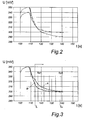
- the measurement can take place continuously, but it is also possible to use individual interpolation point values Sp1 to Sp5 (see FIG Fig. 3 ) during the response time of the sensor.
- Fig. 3 shows the normalized signal curves of the measured data Fig. 2 , where the curves have been normalized such that the curves coincide at time t> 150 s.
- a voltage U (in mV) proportional to the O 2 concentration of the sample for example a blood sample, is plotted as a function of time t (in s).
- the amperometric signal is tapped on a current / voltage converter and measured in the form of a voltage proportional to the current.
- the evaluation of the temporal signal curves with regard to the presence of a gas bubble can be made directly on the basis of the measured voltage values, a conversion of the signal curves into pressure units (pO 2 [mmHg]) and the evaluation based on pressure units is possible but not necessary with the help of calibration data ,
- an amperometric O 2 sensor is adjusted to a pO 2 of about 160 Torr with a suitable calibration medium, and then with a blood sample. which has a lower pO 2 (for example, 140 Torr) brought into contact, it is observed over the time t an exponentially decreasing waveform.
- the signal change (dS / dt) tends towards the value zero.
- the term t 99 is understood to mean the time after which 99% of the signal change has passed.
- the profile of the waveform reflects the diffusion processes of the oxygen from the sensor into the sample or from the sample into the sensor.
- pO 2 value of the sensor 7 is to be understood that pO 2 which have the materials of the sensor in the immediate vicinity of the sensitive elements.
- pO 2 value of the sample is that pO 2 value to be understood to comprise the samples of play present in the immediate vicinity of the sensitive area of the sensor 8. 7
- the different signal curves can be explained by different diffusion properties, diffusion paths and gas quantities in the presence or absence of a gas bubble. If it is e.g. A gas bubble in the immediate vicinity of the sensor thus results in different diffusion paths and different gas reservoirs compared to a gas bubble-free measuring liquid. Within a gas bubble, diffusion kinetics are generally faster than within an aqueous liquid. In general, a gas bubble contains more gas than an aqueous liquid of equal volume.
Landscapes
- Health & Medical Sciences (AREA)
- Life Sciences & Earth Sciences (AREA)
- Chemical & Material Sciences (AREA)
- Engineering & Computer Science (AREA)
- Physics & Mathematics (AREA)
- Biomedical Technology (AREA)
- Pathology (AREA)
- Hematology (AREA)
- Biochemistry (AREA)
- General Health & Medical Sciences (AREA)
- General Physics & Mathematics (AREA)
- Immunology (AREA)
- Molecular Biology (AREA)
- Analytical Chemistry (AREA)
- Chemical Kinetics & Catalysis (AREA)
- Ecology (AREA)
- Electrochemistry (AREA)
- Biophysics (AREA)
- Urology & Nephrology (AREA)
- Food Science & Technology (AREA)
- Medicinal Chemistry (AREA)
- Investigating Or Analysing Biological Materials (AREA)
- Sampling And Sample Adjustment (AREA)
- Measurement Of The Respiration, Hearing Ability, Form, And Blood Characteristics Of Living Organisms (AREA)
- Investigating Or Analyzing Materials By The Use Of Electric Means (AREA)
Claims (6)
- Procédé pour la détection d'une bulle gazeuse, de préférence une bulle d'air, dans un liquide aqueux, de préférence un liquide de calibrage, de contrôle ou d'échantillon, laquelle bulle gazeuse se trouve dans un contact au moins partiel avec la zone sensible d'un capteur disposé dans une chambre de mesure pour la détermination de la concentration d'un composant de gaz dissous dans le liquide, caractérisé en ce que◆ une pression partielle de gaz, qui se différencie de la valeur empirique de la pression partielle de gaz du composant de gaz du liquide à mesurer, est réglée sur le capteur au moyen d'un liquide aqueux, d'un gaz ou d'un mélange de gaz, qui contient le composant de gaz àdéterminer dans une concentration appropriée,◆ en ce que le capteur est sollicité avec le liquide à mesurer et un arrêt du liquide de mesure est attendu,◆ en ce que, jusqu'au réglage d'un tracé de signal constant du capteur, son évolution dans le temps est enregistrée et,◆ à partir de l'évolution du signal dans le temps, on conclut à la présence ou à l'absence d'une bulle de gaz.
- Procédé selon la revendication 1, caractérisé en ce que une valeur de signal de la courbe de signal est mesurée à au moins deux moments pendant le temps de réglage du capteur et comparée avec des valeurs connues d'échantillons de mesure sans bulle.
- Procédé selon la revendication 1 ou 2, caractérisé en ce qu'une pression partielle de gaz, qui est supérieure à la pression partielle de gaz du composant de gaz dans le liquide à mesurer, est réglée sur le capteur avant la mesure.
- Procédé selon les revendications 1 à 3, caractérisé en ce que le liquide aqueux pour le réglage de la pression partielle de gaz est un liquide de calibrage, de contrôle ou de lavage tonométré de façon appropriée.
- Procédé selon l'une quelconque des revendications 1 à 4, caractérisé en qu'un capteur de O2 ou de CO2 est utilisé comme capteur.
- Procédé selon l'une quelconque des revendications 1 à 5, caractérisé en ce que l'échantillon de liquide est un liquide biologique, de préférence du sang.
Applications Claiming Priority (1)
| Application Number | Priority Date | Filing Date | Title |
|---|---|---|---|
| AT0146804A AT414172B (de) | 2004-09-02 | 2004-09-02 | Verfahren zur detektion einer gasblase in einer wässrigen flüssigkeit |
Publications (4)
| Publication Number | Publication Date |
|---|---|
| EP1632776A2 EP1632776A2 (fr) | 2006-03-08 |
| EP1632776A3 EP1632776A3 (fr) | 2007-05-23 |
| EP1632776B1 true EP1632776B1 (fr) | 2008-06-04 |
| EP1632776B8 EP1632776B8 (fr) | 2008-07-16 |
Family
ID=35431790
Family Applications (1)
| Application Number | Title | Priority Date | Filing Date |
|---|---|---|---|
| EP05450147A Active EP1632776B8 (fr) | 2004-09-02 | 2005-09-01 | Procédé de détection d'une bulle gazeuse dans un liquide aqueux |
Country Status (5)
| Country | Link |
|---|---|
| US (2) | US7867375B2 (fr) |
| EP (1) | EP1632776B8 (fr) |
| AT (2) | AT414172B (fr) |
| DE (1) | DE502005004329D1 (fr) |
| ES (1) | ES2307139T3 (fr) |
Cited By (1)
| Publication number | Priority date | Publication date | Assignee | Title |
|---|---|---|---|---|
| US8354015B2 (en) | 2004-09-02 | 2013-01-15 | Roche Diagnostics Operations, Inc. | Detection of the presence or absence of a gas bubble by dynamic sensor response |
Families Citing this family (1)
| Publication number | Priority date | Publication date | Assignee | Title |
|---|---|---|---|---|
| WO2019121220A1 (fr) * | 2017-12-22 | 2019-06-27 | Radiometer Medical Aps | Procédé et capteur pour détecter la présence ou l'absence d'un contaminant |
Family Cites Families (14)
| Publication number | Priority date | Publication date | Assignee | Title |
|---|---|---|---|---|
| US3874850A (en) * | 1972-07-24 | 1975-04-01 | Radiometer As | Blood analyzing method and apparatus |
| US3961898A (en) * | 1975-01-14 | 1976-06-08 | The United States Of America As Represented By The Secretary Of The Army | Comparator circuit for automatic analysis apparatus |
| CH625065A5 (fr) * | 1977-11-16 | 1981-08-31 | Avl Ag | |
| EP0355896A3 (fr) | 1988-08-10 | 1990-09-12 | INSTRUMENTATION LABORATORY S.p.A. | Méthode, appareil et solution pour étalonner des pressions partielles |
| US5061631A (en) * | 1988-10-14 | 1991-10-29 | Fisher Scientific Company | Method, apparatus and solution for calibration of partial pressure value |
| JP2643020B2 (ja) | 1990-11-05 | 1997-08-20 | 三菱石油株式会社 | 流動液体中の気泡含有量の動的定量装置 |
| DE19605246A1 (de) * | 1996-02-13 | 1997-08-14 | Siemens Ag | Verfahren zur Eichung von Gasmeßsonsoren für gelöste Gase und Verfahren zur Konzentrationsmessung von CO2 in Blut mit Hilfe eines solchen Eichverfahrens |
| AT409800B (de) | 1999-09-13 | 2002-11-25 | Hoffmann La Roche | Verfahren und vorrichtung zur verbesserung der lagerfähigkeit tonometrierter flüssigkeiten |
| ATE421685T1 (de) | 1999-10-29 | 2009-02-15 | Radiometer Medical Aps | Verfahren und vorrichtung zum nachweis einer gasblase in einer flüssigkeit |
| US6773577B1 (en) * | 2001-09-19 | 2004-08-10 | Teledyne Technologies Incorporated | Electrochemical cell bubble detection |
| AT411627B (de) * | 2002-08-23 | 2004-03-25 | Hoffmann La Roche | Vorrichtung zur überprüfung der positionierung und der blasenfreiheit einer medizinischen mikroprobe in einer durchflussmesszelle |
| AT412515B (de) | 2003-08-07 | 2005-03-25 | Hoffmann La Roche | Verfahren zur detektion einer gasblase in einer flüssigkeit |
| AT502856B1 (de) | 2004-09-02 | 2007-10-15 | Hoffmann La Roche | Verfahren zur detektion einer gasblase in einer wässrigen flüssigkeit |
| AT414172B (de) * | 2004-09-02 | 2006-09-15 | Hoffmann La Roche | Verfahren zur detektion einer gasblase in einer wässrigen flüssigkeit |
-
2004
- 2004-09-02 AT AT0146804A patent/AT414172B/de not_active IP Right Cessation
-
2005
- 2005-08-31 US US11/216,765 patent/US7867375B2/en active Active
- 2005-09-01 AT AT05450147T patent/ATE397750T1/de active
- 2005-09-01 ES ES05450147T patent/ES2307139T3/es active Active
- 2005-09-01 DE DE502005004329T patent/DE502005004329D1/de active Active
- 2005-09-01 EP EP05450147A patent/EP1632776B8/fr active Active
-
2010
- 2010-12-01 US US12/957,513 patent/US8354015B2/en active Active
Cited By (1)
| Publication number | Priority date | Publication date | Assignee | Title |
|---|---|---|---|---|
| US8354015B2 (en) | 2004-09-02 | 2013-01-15 | Roche Diagnostics Operations, Inc. | Detection of the presence or absence of a gas bubble by dynamic sensor response |
Also Published As
| Publication number | Publication date |
|---|---|
| US20060213773A1 (en) | 2006-09-28 |
| US7867375B2 (en) | 2011-01-11 |
| EP1632776A2 (fr) | 2006-03-08 |
| DE502005004329D1 (de) | 2008-07-17 |
| AT414172B (de) | 2006-09-15 |
| US20110067483A1 (en) | 2011-03-24 |
| ES2307139T3 (es) | 2008-11-16 |
| ATE397750T1 (de) | 2008-06-15 |
| EP1632776A3 (fr) | 2007-05-23 |
| ATA14682004A (de) | 2005-12-15 |
| US8354015B2 (en) | 2013-01-15 |
| EP1632776B8 (fr) | 2008-07-16 |
Similar Documents
| Publication | Publication Date | Title |
|---|---|---|
| AT411627B (de) | Vorrichtung zur überprüfung der positionierung und der blasenfreiheit einer medizinischen mikroprobe in einer durchflussmesszelle | |
| DE69434438T2 (de) | Biosensor mit ausfallgesichertem betriebsverfahren zur vermeidung von falschen anzeigen | |
| DE2911943A1 (de) | Elektrochemisches durchflussystem | |
| DE60036980T2 (de) | Verfahren zum Verifizieren eines aspirierten Flüssigkeitsvolumens in einem Automatisiertem Diagnostiksystem | |
| DE2927048C2 (de) | Vorrichtung zur Durchführung analytischer Messungen an einer Flüssigkeit | |
| DE2224703A1 (de) | Elektrochemische Meßeinrichtung | |
| DE2554803A1 (de) | Elektrochemisches analyseverfahren und vorrichtung hierfuer | |
| WO2013135539A1 (fr) | Test de fonctionnement de capteurs de gaz à conductibilité thermique | |
| DE4410224C2 (de) | Miniaturisiertes Durchfluß-Analysesystem | |
| AT412515B (de) | Verfahren zur detektion einer gasblase in einer flüssigkeit | |
| DE2265200C3 (de) | Strömungszelle für Zwecke der elektrochemischen Analyse | |
| EP1632776B1 (fr) | Procédé de détection d'une bulle gazeuse dans un liquide aqueux | |
| EP1632773B1 (fr) | Méthode pour détecter une bulle de gaz dans un liquide aqueux | |
| EP2944952B1 (fr) | Système de détermination du potentiel de zêta destiné à caractériser une limite de phase liquide/solide avec application de profil de pression commandée | |
| EP0995098A1 (fr) | Procede et dispositif pour prelever en serie des echantillons | |
| EP1285266B1 (fr) | Procédé de mesure du contenu de SO2 dans le vin | |
| EP1591778A1 (fr) | Capteur de gaz électrochimique avec un revêtement de membrane hydrophile | |
| EP1591779B1 (fr) | Capteur de gaz électrochimique avec un revêtement de membrane hydrophile | |
| DE4442685C1 (de) | Verfahren und Vorrichtung zur Bestimmung eines Strömungspotentials | |
| DE2726771A1 (de) | Verfahren und vorrichtung zur elektrochemisch-enzymatischen analyse stroemender fluessigkeiten | |
| DE102007004389A1 (de) | Verfahren und Vorrichtung zur Bestimmung der elektrischen Leitfähigkeit einer Probenflüssigkeit | |
| JPS6130754A (ja) | 電気化学センサを用いた検査装置 | |
| DD235916A1 (de) | Verfahren zur vorbereitung von untersuchungsfluessigkeiten fuer fliesssysteme | |
| DD294569A5 (de) | Anordnung zur bestimmung von analyten in fluessigen medien | |
| DE7718741U1 (de) | Vorrichtung zur elektrochemischenzymatischen Analyse strömender Flüssigkeiten |
Legal Events
| Date | Code | Title | Description |
|---|---|---|---|
| PUAI | Public reference made under article 153(3) epc to a published international application that has entered the european phase |
Free format text: ORIGINAL CODE: 0009012 |
|
| AK | Designated contracting states |
Kind code of ref document: A2 Designated state(s): AT BE BG CH CY CZ DE DK EE ES FI FR GB GR HU IE IS IT LI LT LU LV MC NL PL PT RO SE SI SK TR |
|
| AX | Request for extension of the european patent |
Extension state: AL BA HR MK YU |
|
| PUAL | Search report despatched |
Free format text: ORIGINAL CODE: 0009013 |
|
| RIC1 | Information provided on ipc code assigned before grant |
Ipc: G01N 33/49 20060101AFI20051207BHEP Ipc: G01N 27/416 20060101ALI20070411BHEP Ipc: G01N 7/00 20060101ALI20070411BHEP |
|
| AK | Designated contracting states |
Kind code of ref document: A3 Designated state(s): AT BE BG CH CY CZ DE DK EE ES FI FR GB GR HU IE IS IT LI LT LU LV MC NL PL PT RO SE SI SK TR |
|
| AX | Request for extension of the european patent |
Extension state: AL BA HR MK YU |
|
| AKX | Designation fees paid | ||
| 17P | Request for examination filed |
Effective date: 20070627 |
|
| RBV | Designated contracting states (corrected) |
Designated state(s): AT BE BG CH CY CZ DE DK EE ES FI FR GB GR HU IE IS IT LI LT LU LV MC NL PL PT RO SE SI SK TR |
|
| GRAP | Despatch of communication of intention to grant a patent |
Free format text: ORIGINAL CODE: EPIDOSNIGR1 |
|
| REG | Reference to a national code |
Ref country code: DE Ref legal event code: 8566 |
|
| GRAS | Grant fee paid |
Free format text: ORIGINAL CODE: EPIDOSNIGR3 |
|
| GRAA | (expected) grant |
Free format text: ORIGINAL CODE: 0009210 |
|
| AK | Designated contracting states |
Kind code of ref document: B1 Designated state(s): AT BE BG CH CY CZ DE DK EE ES FI FR GB GR HU IE IS IT LI LT LU LV MC NL PL PT RO SE SI SK TR |
|
| REG | Reference to a national code |
Ref country code: GB Ref legal event code: FG4D Free format text: NOT ENGLISH |
|
| RAP2 | Party data changed (patent owner data changed or rights of a patent transferred) |
Owner name: ROCHE DIAGNOSTICS GMBH Owner name: F. HOFFMANN-LA ROCHE AG |
|
| REG | Reference to a national code |
Ref country code: CH Ref legal event code: EP |
|
| REF | Corresponds to: |
Ref document number: 502005004329 Country of ref document: DE Date of ref document: 20080717 Kind code of ref document: P |
|
| REG | Reference to a national code |
Ref country code: CH Ref legal event code: NV Representative=s name: BOHEST AG |
|
| REG | Reference to a national code |
Ref country code: IE Ref legal event code: FG4D Free format text: LANGUAGE OF EP DOCUMENT: GERMAN |
|
| NLT2 | Nl: modifications (of names), taken from the european patent patent bulletin |
Owner name: F. HOFFMANN-LA ROCHE AG Effective date: 20080625 |
|
| PG25 | Lapsed in a contracting state [announced via postgrant information from national office to epo] |
Ref country code: SI Free format text: LAPSE BECAUSE OF FAILURE TO SUBMIT A TRANSLATION OF THE DESCRIPTION OR TO PAY THE FEE WITHIN THE PRESCRIBED TIME-LIMIT Effective date: 20080604 Ref country code: FI Free format text: LAPSE BECAUSE OF FAILURE TO SUBMIT A TRANSLATION OF THE DESCRIPTION OR TO PAY THE FEE WITHIN THE PRESCRIBED TIME-LIMIT Effective date: 20080604 |
|
| REG | Reference to a national code |
Ref country code: ES Ref legal event code: FG2A Ref document number: 2307139 Country of ref document: ES Kind code of ref document: T3 |
|
| PG25 | Lapsed in a contracting state [announced via postgrant information from national office to epo] |
Ref country code: LV Free format text: LAPSE BECAUSE OF FAILURE TO SUBMIT A TRANSLATION OF THE DESCRIPTION OR TO PAY THE FEE WITHIN THE PRESCRIBED TIME-LIMIT Effective date: 20080604 Ref country code: NL Free format text: LAPSE BECAUSE OF FAILURE TO SUBMIT A TRANSLATION OF THE DESCRIPTION OR TO PAY THE FEE WITHIN THE PRESCRIBED TIME-LIMIT Effective date: 20080604 Ref country code: PL Free format text: LAPSE BECAUSE OF FAILURE TO SUBMIT A TRANSLATION OF THE DESCRIPTION OR TO PAY THE FEE WITHIN THE PRESCRIBED TIME-LIMIT Effective date: 20080604 |
|
| NLV1 | Nl: lapsed or annulled due to failure to fulfill the requirements of art. 29p and 29m of the patents act | ||
| REG | Reference to a national code |
Ref country code: IE Ref legal event code: FD4D |
|
| PG25 | Lapsed in a contracting state [announced via postgrant information from national office to epo] |
Ref country code: LT Free format text: LAPSE BECAUSE OF FAILURE TO SUBMIT A TRANSLATION OF THE DESCRIPTION OR TO PAY THE FEE WITHIN THE PRESCRIBED TIME-LIMIT Effective date: 20080604 Ref country code: CZ Free format text: LAPSE BECAUSE OF FAILURE TO SUBMIT A TRANSLATION OF THE DESCRIPTION OR TO PAY THE FEE WITHIN THE PRESCRIBED TIME-LIMIT Effective date: 20080604 Ref country code: SE Free format text: LAPSE BECAUSE OF FAILURE TO SUBMIT A TRANSLATION OF THE DESCRIPTION OR TO PAY THE FEE WITHIN THE PRESCRIBED TIME-LIMIT Effective date: 20080904 Ref country code: IE Free format text: LAPSE BECAUSE OF FAILURE TO SUBMIT A TRANSLATION OF THE DESCRIPTION OR TO PAY THE FEE WITHIN THE PRESCRIBED TIME-LIMIT Effective date: 20080604 Ref country code: IS Free format text: LAPSE BECAUSE OF FAILURE TO SUBMIT A TRANSLATION OF THE DESCRIPTION OR TO PAY THE FEE WITHIN THE PRESCRIBED TIME-LIMIT Effective date: 20081004 |
|
| PG25 | Lapsed in a contracting state [announced via postgrant information from national office to epo] |
Ref country code: SK Free format text: LAPSE BECAUSE OF FAILURE TO SUBMIT A TRANSLATION OF THE DESCRIPTION OR TO PAY THE FEE WITHIN THE PRESCRIBED TIME-LIMIT Effective date: 20080604 Ref country code: PT Free format text: LAPSE BECAUSE OF FAILURE TO SUBMIT A TRANSLATION OF THE DESCRIPTION OR TO PAY THE FEE WITHIN THE PRESCRIBED TIME-LIMIT Effective date: 20081104 Ref country code: RO Free format text: LAPSE BECAUSE OF FAILURE TO SUBMIT A TRANSLATION OF THE DESCRIPTION OR TO PAY THE FEE WITHIN THE PRESCRIBED TIME-LIMIT Effective date: 20080604 |
|
| BERE | Be: lapsed |
Owner name: F. HOFFMANN-LA ROCHE A.G. Effective date: 20080930 |
|
| PLBE | No opposition filed within time limit |
Free format text: ORIGINAL CODE: 0009261 |
|
| STAA | Information on the status of an ep patent application or granted ep patent |
Free format text: STATUS: NO OPPOSITION FILED WITHIN TIME LIMIT |
|
| PG25 | Lapsed in a contracting state [announced via postgrant information from national office to epo] |
Ref country code: MC Free format text: LAPSE BECAUSE OF NON-PAYMENT OF DUE FEES Effective date: 20080930 Ref country code: EE Free format text: LAPSE BECAUSE OF FAILURE TO SUBMIT A TRANSLATION OF THE DESCRIPTION OR TO PAY THE FEE WITHIN THE PRESCRIBED TIME-LIMIT Effective date: 20080604 Ref country code: DK Free format text: LAPSE BECAUSE OF FAILURE TO SUBMIT A TRANSLATION OF THE DESCRIPTION OR TO PAY THE FEE WITHIN THE PRESCRIBED TIME-LIMIT Effective date: 20080604 Ref country code: BG Free format text: LAPSE BECAUSE OF FAILURE TO SUBMIT A TRANSLATION OF THE DESCRIPTION OR TO PAY THE FEE WITHIN THE PRESCRIBED TIME-LIMIT Effective date: 20080904 |
|
| 26N | No opposition filed |
Effective date: 20090305 |
|
| PG25 | Lapsed in a contracting state [announced via postgrant information from national office to epo] |
Ref country code: BE Free format text: LAPSE BECAUSE OF NON-PAYMENT OF DUE FEES Effective date: 20080930 |
|
| PG25 | Lapsed in a contracting state [announced via postgrant information from national office to epo] |
Ref country code: LU Free format text: LAPSE BECAUSE OF NON-PAYMENT OF DUE FEES Effective date: 20080901 Ref country code: HU Free format text: LAPSE BECAUSE OF FAILURE TO SUBMIT A TRANSLATION OF THE DESCRIPTION OR TO PAY THE FEE WITHIN THE PRESCRIBED TIME-LIMIT Effective date: 20081205 Ref country code: CY Free format text: LAPSE BECAUSE OF FAILURE TO SUBMIT A TRANSLATION OF THE DESCRIPTION OR TO PAY THE FEE WITHIN THE PRESCRIBED TIME-LIMIT Effective date: 20080604 |
|
| PG25 | Lapsed in a contracting state [announced via postgrant information from national office to epo] |
Ref country code: TR Free format text: LAPSE BECAUSE OF FAILURE TO SUBMIT A TRANSLATION OF THE DESCRIPTION OR TO PAY THE FEE WITHIN THE PRESCRIBED TIME-LIMIT Effective date: 20080604 |
|
| PG25 | Lapsed in a contracting state [announced via postgrant information from national office to epo] |
Ref country code: GR Free format text: LAPSE BECAUSE OF FAILURE TO SUBMIT A TRANSLATION OF THE DESCRIPTION OR TO PAY THE FEE WITHIN THE PRESCRIBED TIME-LIMIT Effective date: 20080905 |
|
| REG | Reference to a national code |
Ref country code: CH Ref legal event code: PCAR Free format text: NEW ADDRESS: HOLBEINSTRASSE 36-38, 4051 BASEL (CH) |
|
| PGFP | Annual fee paid to national office [announced via postgrant information from national office to epo] |
Ref country code: CH Payment date: 20140725 Year of fee payment: 10 |
|
| PGFP | Annual fee paid to national office [announced via postgrant information from national office to epo] |
Ref country code: AT Payment date: 20140825 Year of fee payment: 10 Ref country code: ES Payment date: 20140904 Year of fee payment: 10 |
|
| PGFP | Annual fee paid to national office [announced via postgrant information from national office to epo] |
Ref country code: IT Payment date: 20140922 Year of fee payment: 10 |
|
| PG25 | Lapsed in a contracting state [announced via postgrant information from national office to epo] |
Ref country code: IT Free format text: LAPSE BECAUSE OF NON-PAYMENT OF DUE FEES Effective date: 20150901 |
|
| REG | Reference to a national code |
Ref country code: CH Ref legal event code: PL |
|
| REG | Reference to a national code |
Ref country code: AT Ref legal event code: MM01 Ref document number: 397750 Country of ref document: AT Kind code of ref document: T Effective date: 20150901 |
|
| PG25 | Lapsed in a contracting state [announced via postgrant information from national office to epo] |
Ref country code: LI Free format text: LAPSE BECAUSE OF NON-PAYMENT OF DUE FEES Effective date: 20150930 Ref country code: CH Free format text: LAPSE BECAUSE OF NON-PAYMENT OF DUE FEES Effective date: 20150930 |
|
| REG | Reference to a national code |
Ref country code: FR Ref legal event code: PLFP Year of fee payment: 12 |
|
| PG25 | Lapsed in a contracting state [announced via postgrant information from national office to epo] |
Ref country code: AT Free format text: LAPSE BECAUSE OF NON-PAYMENT OF DUE FEES Effective date: 20150901 |
|
| REG | Reference to a national code |
Ref country code: ES Ref legal event code: FD2A Effective date: 20161027 |
|
| PG25 | Lapsed in a contracting state [announced via postgrant information from national office to epo] |
Ref country code: ES Free format text: LAPSE BECAUSE OF NON-PAYMENT OF DUE FEES Effective date: 20150902 |
|
| REG | Reference to a national code |
Ref country code: FR Ref legal event code: PLFP Year of fee payment: 13 |
|
| REG | Reference to a national code |
Ref country code: FR Ref legal event code: PLFP Year of fee payment: 14 |
|
| PGFP | Annual fee paid to national office [announced via postgrant information from national office to epo] |
Ref country code: FR Payment date: 20200814 Year of fee payment: 16 |
|
| PG25 | Lapsed in a contracting state [announced via postgrant information from national office to epo] |
Ref country code: FR Free format text: LAPSE BECAUSE OF NON-PAYMENT OF DUE FEES Effective date: 20210930 |
|
| PGFP | Annual fee paid to national office [announced via postgrant information from national office to epo] |
Ref country code: GB Payment date: 20230823 Year of fee payment: 19 |
|
| PGFP | Annual fee paid to national office [announced via postgrant information from national office to epo] |
Ref country code: DE Payment date: 20230822 Year of fee payment: 19 |