EP1632742A2 - Wärmeübertrager, insbesondere für Klimaanlage - Google Patents
Wärmeübertrager, insbesondere für Klimaanlage Download PDFInfo
- Publication number
- EP1632742A2 EP1632742A2 EP05016196A EP05016196A EP1632742A2 EP 1632742 A2 EP1632742 A2 EP 1632742A2 EP 05016196 A EP05016196 A EP 05016196A EP 05016196 A EP05016196 A EP 05016196A EP 1632742 A2 EP1632742 A2 EP 1632742A2
- Authority
- EP
- European Patent Office
- Prior art keywords
- heat exchanger
- flat tubes
- narrow sides
- width
- flat
- Prior art date
- Legal status (The legal status is an assumption and is not a legal conclusion. Google has not performed a legal analysis and makes no representation as to the accuracy of the status listed.)
- Granted
Links
- 238000004378 air conditioning Methods 0.000 title abstract description 4
- 239000003570 air Substances 0.000 description 10
- 239000006228 supernatant Substances 0.000 description 7
- 238000010276 construction Methods 0.000 description 3
- 239000003507 refrigerant Substances 0.000 description 3
- 210000002816 gill Anatomy 0.000 description 2
- 238000004519 manufacturing process Methods 0.000 description 2
- 239000011435 rock Substances 0.000 description 2
- 239000012080 ambient air Substances 0.000 description 1
- 238000003491 array Methods 0.000 description 1
- 230000015572 biosynthetic process Effects 0.000 description 1
- 238000009434 installation Methods 0.000 description 1
- 238000000034 method Methods 0.000 description 1
- 238000005057 refrigeration Methods 0.000 description 1
- 239000004575 stone Substances 0.000 description 1
- 238000011144 upstream manufacturing Methods 0.000 description 1
Images

Classifications
-
- F—MECHANICAL ENGINEERING; LIGHTING; HEATING; WEAPONS; BLASTING
- F28—HEAT EXCHANGE IN GENERAL
- F28F—DETAILS OF HEAT-EXCHANGE AND HEAT-TRANSFER APPARATUS, OF GENERAL APPLICATION
- F28F1/00—Tubular elements; Assemblies of tubular elements
- F28F1/10—Tubular elements and assemblies thereof with means for increasing heat-transfer area, e.g. with fins, with projections, with recesses
- F28F1/12—Tubular elements and assemblies thereof with means for increasing heat-transfer area, e.g. with fins, with projections, with recesses the means being only outside the tubular element
- F28F1/126—Tubular elements and assemblies thereof with means for increasing heat-transfer area, e.g. with fins, with projections, with recesses the means being only outside the tubular element consisting of zig-zag shaped fins
-
- F—MECHANICAL ENGINEERING; LIGHTING; HEATING; WEAPONS; BLASTING
- F28—HEAT EXCHANGE IN GENERAL
- F28D—HEAT-EXCHANGE APPARATUS, NOT PROVIDED FOR IN ANOTHER SUBCLASS, IN WHICH THE HEAT-EXCHANGE MEDIA DO NOT COME INTO DIRECT CONTACT
- F28D1/00—Heat-exchange apparatus having stationary conduit assemblies for one heat-exchange medium only, the media being in contact with different sides of the conduit wall, in which the other heat-exchange medium is a large body of fluid, e.g. domestic or motor car radiators
- F28D1/02—Heat-exchange apparatus having stationary conduit assemblies for one heat-exchange medium only, the media being in contact with different sides of the conduit wall, in which the other heat-exchange medium is a large body of fluid, e.g. domestic or motor car radiators with heat-exchange conduits immersed in the body of fluid
- F28D1/04—Heat-exchange apparatus having stationary conduit assemblies for one heat-exchange medium only, the media being in contact with different sides of the conduit wall, in which the other heat-exchange medium is a large body of fluid, e.g. domestic or motor car radiators with heat-exchange conduits immersed in the body of fluid with tubular conduits
- F28D1/053—Heat-exchange apparatus having stationary conduit assemblies for one heat-exchange medium only, the media being in contact with different sides of the conduit wall, in which the other heat-exchange medium is a large body of fluid, e.g. domestic or motor car radiators with heat-exchange conduits immersed in the body of fluid with tubular conduits the conduits being straight
- F28D1/0535—Heat-exchange apparatus having stationary conduit assemblies for one heat-exchange medium only, the media being in contact with different sides of the conduit wall, in which the other heat-exchange medium is a large body of fluid, e.g. domestic or motor car radiators with heat-exchange conduits immersed in the body of fluid with tubular conduits the conduits being straight the conduits having a non-circular cross-section
- F28D1/05366—Assemblies of conduits connected to common headers, e.g. core type radiators
- F28D1/05383—Assemblies of conduits connected to common headers, e.g. core type radiators with multiple rows of conduits or with multi-channel conduits
-
- F—MECHANICAL ENGINEERING; LIGHTING; HEATING; WEAPONS; BLASTING
- F28—HEAT EXCHANGE IN GENERAL
- F28F—DETAILS OF HEAT-EXCHANGE AND HEAT-TRANSFER APPARATUS, OF GENERAL APPLICATION
- F28F1/00—Tubular elements; Assemblies of tubular elements
- F28F1/02—Tubular elements of cross-section which is non-circular
- F28F1/022—Tubular elements of cross-section which is non-circular with multiple channels
-
- F—MECHANICAL ENGINEERING; LIGHTING; HEATING; WEAPONS; BLASTING
- F28—HEAT EXCHANGE IN GENERAL
- F28F—DETAILS OF HEAT-EXCHANGE AND HEAT-TRANSFER APPARATUS, OF GENERAL APPLICATION
- F28F1/00—Tubular elements; Assemblies of tubular elements
- F28F1/10—Tubular elements and assemblies thereof with means for increasing heat-transfer area, e.g. with fins, with projections, with recesses
- F28F1/12—Tubular elements and assemblies thereof with means for increasing heat-transfer area, e.g. with fins, with projections, with recesses the means being only outside the tubular element
- F28F1/126—Tubular elements and assemblies thereof with means for increasing heat-transfer area, e.g. with fins, with projections, with recesses the means being only outside the tubular element consisting of zig-zag shaped fins
- F28F1/128—Fins with openings, e.g. louvered fins
-
- F—MECHANICAL ENGINEERING; LIGHTING; HEATING; WEAPONS; BLASTING
- F28—HEAT EXCHANGE IN GENERAL
- F28F—DETAILS OF HEAT-EXCHANGE AND HEAT-TRANSFER APPARATUS, OF GENERAL APPLICATION
- F28F2265/00—Safety or protection arrangements; Arrangements for preventing malfunction
Definitions
- the invention relates to a heat exchanger, in particular for air conditioning systems, according to the preamble of claim 1.
- Pressure-stable heat exchangers are known in particular for automotive air conditioning systems which are operated with CO2 or R744.
- the high pressures occurring in the supercritical refrigeration process require a pressure-stable design of the tubes carrying the refrigerant and the associated collection container, which are preferably designed as thick-walled headers.
- the tubes are often designed as extruded multi-chamber tubes, in particular with circular or elliptical cross sections.
- This design has the advantage, inter alia, that the diameter of the collecting pipes in relation to the pipe width (measured in the direction of air flow) can be chosen to be relatively small.
- the flat tube ends are twisted by 90 ° and taken in a preferably continuous longitudinal slot so compact that their narrow sides (relative to the flat tube cross-section) are close to each other.
- the flat tube ends are soldered to the slotted manifold and thus form a pressure-stable heat exchanger, which withstands the occurring pressures of about 120 bar.
- a problem with this construction is derived from the fact that between the block depth, which corresponds to the pipe and corrugated fin width (measured in the air flow direction), and the pipe pitch is a fixed relationship: the pitch of the tubes corresponds to their width or the sum of fin height and pipe thickness.
- the block depth which is a measure of the efficiency of the heat exchanger, can not be increased without further ado - rather, this block design has a limitation on the block depth.
- a so-called one-sided rib projection is provided for the corrugated ribs, d. H.
- the corrugated fins arranged between the flat tubes project to one side over the narrow sides of the flat tubes and terminate flush with the other side (end face).
- the advantage of a higher heat transfer performance is achieved by improving the air-side heat transfer.
- there are advantages in the production because one side (end face) of the heat exchanger block is smooth and thus can be placed on a flat surface during "Kassettieren".
- the fin projection can be arranged on the inflow side (windward side) or the outflow side (leeward side) of the heat exchanger.
- a gas cooler or condenser which can preferably be arranged in the front engine compartment of a motor vehicle
- a better condensate would result in circumstances, if the fin overhang on the leeward side of the evaporator is arranged.
- the supernatant based on the width of the flat tubes (measured in Luftströmungshchtung) about 25% and less.
- the fin protrusion is in a range of 5-20% of the flashback width, with a low percentage being preferred for large widths and a higher percentage for small widths, so as to approximate the absolute dimensions for the fin protrusion.
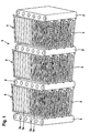
- Fig. 1 shows a perspective view of a heat exchanger block 1, hereinafter referred to as block, wherein the entire heat exchanger is not shown, but in its construction of the aforementioned printing step of the Applicant, DE-A 198 46 267, which hereby fully in full the disclosure of this application is included.
- the block 1 has flat tubes 2, between which corrugated fins 3 are arranged, which are soldered with their wave crests with the flat sides of the flat tubes 2.
- the flat tubes 2 are formed as extruded multi-chamber tubes with circular or elliptical flow channels 2a. The ends of the flat tubes 2, not shown, are twisted and received in a longitudinal section, not shown, of a collecting tube.
- the corrugated fins 3 have - what is known - gills or gill arrays 3a for improvement the heat transfer on.
- the corrugated fins 3 are overflowed by ambient air, while the flow channels 2a of the flat tubes 2 are traversed by a supercritical refrigerant, preferably R744 or CO2, which flows through a refrigerant circuit, not shown, of a motor vehicle air conditioner.
- the corrugated fins 3 are on one side (in the drawing, the upper) in the air flow direction beyond the tubes, ie, they form a so-called fin projection 4, which is only distorted recognizable in the perspective view and will therefore be explained in more detail below.
- Fig. 2 shows the same section of the block 1 in a cross section through the flat tubes 2.
- the flat tubes 2 have narrow sides 5 on one side of the block 1 and narrow sides 6 on the other side of the block 2.
- the air flow direction is represented by arrows L.
- the rib supernatant 4 is arranged in the illustrated embodiment on the air inflow side (windward side), that is, the corrugated fins 3 are opposite to the air flow direction L on the narrow sides 6 of the flat tubes by an amount Ü addition.
- the width of the flat tubes 2, measured in the direction of air flow L, is B, while the total width of the corrugated fins 3, including the fin projection Ü, is marked B '.
- the rib height is denoted by H, the tube thickness by D and the pitch of the flat tubes 2, ie their center distance with t.
- the dimension Ü for the unilateral rib projection 4 is preferably 25% of the flat tube width B; in particular, a range Ü of 5 to 20% of the flat tube width B is preferred for the rib protrusion 4.
- a range Ü of 5 to 20% of the flat tube width B is preferred for the rib protrusion 4.
- the rib supernatant 4 is on the windward side.
- This embodiment is advantageous, for example, for a gas cooler, which is arranged in the front region of the engine compartment of a motor vehicle, because the rib projection 4 proves to protect the narrow sides 6 against falling rocks.
- the rib supernatant may also be arranged on the leeward side, for. B. in an evaporator, which is located inside an air conditioner and therefore is not exposed to stone chipping.
- condensate formation occurs in the evaporator. This condensate can flow better at a leeward rib protrusion.
- the power gain is due to the rib supernatant, d. H. its dimension Ü regardless of whether it is located on the upstream or the downstream side of the corrugated fins 3.
Landscapes
- Engineering & Computer Science (AREA)
- Physics & Mathematics (AREA)
- Thermal Sciences (AREA)
- Mechanical Engineering (AREA)
- General Engineering & Computer Science (AREA)
- Geometry (AREA)
- Heat-Exchange Devices With Radiators And Conduit Assemblies (AREA)
Abstract
Description
- Die Erfindung betrifft einen Wärmeübertrager, insbesondere für Klimaanlagen, nach dem Oberbegriff des Patentanspruches 1.
- Druckstabile Wärmeübertrager sind insbesondere für Kraftfahrzeug-Klimaanlagen bekannt, die mit CO2 bzw. R744 betrieben werden. Die in dem überkritischen Kälteprozess auftretenden hohen Drücke erfordern eine druckstabile Ausbildung der das Kältemittel führenden Rohre sowie der zugehörigen Sammelbehälter, die vorzugsweise als dickwandige Sammelrohre ausgeführt sind. Die Rohre sind vielfach als extrudierte Mehrkammerrohre, insbesondere mit kreisförmigen oder elliptischen Querschnitten ausgebildet. Durch die DE-A 196 49 129 sowie die DE-A 198 46 267 der Anmelderin wurden druckstabile Wärmeübertrager mit Flachrohren bekannt, deren Endabschnitte um die Rohrlängsachse tordiert und in Öffnungen von Sammelrohren aufgenommen sind. Diese Bauweise hat u. a. den Vorteil, dass der Durchmesser der Sammelrohre in Relation zur Rohrbreite (gemessen in Luftströmungsrichtung) relativ gering gewählt werden kann. Bei der Bauweise nach der DE-A 198 46 267 sind die Flachrohrenden um 90° tordiert und in einem vorzugsweise durchgehenden Längsschlitz derart kompakt aufgenommen, dass ihre Schmalseiten (bezogen auf den Flachrohrquerschnitt) dicht aneinander liegen. Die Flachrohrenden werden mit dem geschlitzten Sammelrohr verlötet und bilden so einen druckstabilen Wärmeübertrager, welcher den auftretenden Drücken von ca. 120 bar standhält.
- Ein Problem bei dieser Bauweise leitet sich daraus ab, dass zwischen der Blocktiefe, die der Rohr- und Wellrippenbreite (gemessen in Luftströmungsrichtung) entspricht, und der Rohrteilung ein fester Zusammenhang besteht: die Teilung der Rohre entspricht ihrer Breite bzw. der Summe aus Rippenhöhe und Rohrdicke. Bei vorgegebener Rippenhöhe lässt sich somit die Blocktiefe, welche ein Maß für die Leistungsfähigkeit des Wärmeübertragers ist, nicht ohne weiteres erhöhen - vielmehr liegt bei dieser Bauweise eine Beschränkung hinsichtlich der Blocktiefe vor.
- Es ist Aufgabe der vorliegenden Erfindung, einen Wärmeübertrager der eingangs genannten Art hinsichtlich seiner Leistungsfähigkeit zu verbessem.
- Diese Aufgabe wird durch die Merkmale des Patentanspruches 1 gelöst. Erfindungsgemäß ist für die Wellrippen ein so genannter einseitiger Rippenüberstand vorgesehen, d. h. die zwischen den Flachrohren angeordneten Wellrippen stehen nach einer Seite über die Schmalseiten der Flachrohre vor und schließen mit der anderen Seite (Stimfläche) bündig ab. Mit diesem Rippenüberstand wird der Vorteil einer höheren Wärmeübertragungsleistung durch Verbesserung des luftseitigen Wärmeüberganges erzielt. Femer ergeben sich bei der Herstellung Vorteile, weil eine Seite (Stimfläche) des Wärmeübertragerblockes glatt ist und somit beim "Kassettieren" auf eine ebene Unterlage gelegt werden kann. Bei einem beiderseitigen Rippenüberstand beispielsweise wäre die Fertigung unter Umständen komplizierter, weil die Flachrohre in Luftströmungsrichtung zwischen den Schmalseiten (Anströmkanten und Abströmkanten) der Flachrohre exakt positioniert werden müssten. Dies würde spezielle Vorrichtungen erfordern, die im Falle des erfindungsgemäßen einseitigen Rippenüberstandes nicht notwendig sind.
- Der Rippenüberstand kann - je nach Anwendungsfall - auf der Anströmseite (Luvseite) oder der Abströmseite (Leeseite) des Wärmeübertragers angeordnet sein: Beispielsweise bei einem Gaskühler oder Kondensator, welcher vorzugsweise im vorderen Motorraum eines Kraftfahrzeuges angeordnet sein kann, ergibt sich durch die vorstehenden Rippen ein Schutz der Flachrohre gegen Steinschlag - unter Umständen als zusätzlicher Vorteil zum verbesserten Wärmeübergang. Beispielsweise bei einem Verdampfer dagegen, auf dessen Rippen sich regelmäßig Kondensat sammelt, würde sich unter Umständen ein besserer Kondensatablauf dadurch ergeben, wenn der Rippenüberstand auf der Leeseite des Verdampfers angeordnet ist.
- Nach einer vorteilhaften Weiterbildung der Erfindung beträgt der Überstand, bezogen auf die Breite der Flachrohre (gemessen in Luftströmungshchtung) etwa 25 % und weniger. Vorzugsweise liegt der Rippenüberstand in einem Bereich von 5 - 20 % der Flachruhrbreite, wobei für große Breiten ein niedriger Prozentsatz und für kleine Breiten ein höherer Prozentsatz bevorzugt wird, so dass sich die absoluten Maße für den Rippenüberstand annähem.
- Ein Ausführungsbeispiel der Erfindung ist in der Zeichnung dargestellt und wird im Folgenden näher beschrieben. Es zeigen
- Fig. 1
- einen perspektivischen Ausschnitt eines Blockes für einen erfindungsgemäßen Wärmeübertrager mit einseitigem Rippenüberstand und
- Fig. 2
- den Blockausschnitt gemäß Fig. 1 als Querschnitt durch die Flachrohre.
- Fig. 1 zeigt eine perspektivische Darstellung eines Wärmeübertragerblockes 1, im Folgenden kurz Block genannt, wobei der gesamte Wärmeübertrager nicht dargestellt ist, jedoch in seiner Bauweise der eingangs genannten Druckschritt der Anmelderin, der DE-A 198 46 267 entspricht, die hiermit voll umfänglich in den Offenbarungsgehalt dieser Anmeldung einbezogen wird. Der Block 1 weist Flachrohre 2 auf, zwischen denen Wellrippen 3 angeordnet sind, die mit ihren Wellenkämmen mit den flachen Seiten der Flachrohre 2 verlötet sind. Die Flachrohre 2 sind als extrudierte Mehrkammerrohre mit kreisförmig oder elliptisch ausgebildeten Strömungskanälen 2a ausgebildet. Die nicht dargestellten Enden der Flachrohre 2 sind tordiert und in einem nicht dargestellten Längsschnitt eines Sammelrohres aufgenommen. Dadurch ergibt sich eine feste Relation zwischen Rohrteilung und Rohrbreite, auf die unten noch genauer eingegangen wird. Die Wellrippen 3 weisen - was an sich bekannt ist - Kiemen bzw. Kiemenfelder 3a zur Verbesserung des Wärmeüberganges auf. Die Wellrippen 3 werden von Umgebungsluft überströmt, während die Strömungskanäle 2a der Flachrohre 2 von einem überkritischen Kältemittel, vorzugsweise R744 bzw. CO2 durchströmt werden, welches einen nicht dargestellten Kältemittelkreislauf einer Kraftfahrzeug-Klimaanlage durchströmt. Die Wellrippen 3 stehen auf einer Seite (in der Zeichnung die obere) in Luftströmungsrichtung über die Rohre hinaus, d-h, sie bilden einen so genannten Rippenüberstand 4, welcher in der perspektivischen Darstellung nur verzerrt erkennbar ist und daher im Folgenden genauer erläutert wird.
- Fig. 2 zeigt den gleichen Ausschnitt des Blockes 1 in einem Querschnitt durch die Flachrohre 2. Es werden die gleichen Bezugszahlen wie zuvor verwendet. Die Flachrohre 2 weisen Schmalseiten 5 auf einer Seite des Blockes 1 und Schmalseiten 6 auf der anderen Seite des Blockes 2 auf. Die Luftströmungsrichtung ist durch Pfeile L dargestellt. Der Rippenüberstand 4 ist bei dem dargestellten Ausführungsbeispiel auf der Luftanströmseite (Luvseite) angeordnet, das heißt die Wellrippen 3 stehen entgegen der Luftströmungsrichtung L über die Schmalseiten 6 der Flachrohre um einen Betrag Ü hinaus. Die Breite der Flachrohre 2, gemessen in Luftströmungsrichtung L beträgt B, während die Gesamtbreite der Wellrippen 3 einschließlich des Rippenüberstandes Ü mit B' gekennzeichnet ist. Die Rippenhöhe ist mit H, die Rohrdicke mit D und die Teilung der Flachrohre 2, d. h. ihr Mittenabstand mit t gekennzeichnet. Aufgrund der obigen Ausführungen ergibt sich für die Teilung folgende Relation:

- Andererseits entspricht die Teilung t aufgrund der um 90° tordierten Flachrohrenden der Flachrohrbreite B:

- Das Maß Ü für den einseitigen Rippenüberstand 4 beträgt vorzugsweise 25 % der Flachrohrbreite B; insbesondere ist für den Rippenüberstand 4 ein Bereich Ü von 5 bis 20 % der Flachrohrbreite B bevorzugt. In diesem Bereich ergibt sich einerseits eine Erhöhung des Wärmeübergangs und damit eine Leistungsverbesserung für den gesamten Wärmeübertrager, andererseits ist die Gefahr von Beschädigungen beim Transport oder der Montage relativ gering.
- Im Ausführungsbeispiel gemäß Fig. 2 liegt der Rippenüberstand 4 auf der Luvseite. Diese Ausführung ist beispielsweise für einen Gaskühler, der im vorderen Bereich des Motorraumes eines Kraftfahrzeuges angeordnet ist, von Vorteil, weil sich der Rippenüberstand 4 als Schutz der Schmalseiten 6 gegen Steinschlag erweist. Andererseits kann der Rippenüberstand auch auf der Leeseite angeordnet sein, z. B. bei einem Verdampfer, der sich im Inneren eines Klimagerätes befindet und daher keinem Steinschlag ausgesetzt ist. Dagegen tritt beim Verdampfer Kondensatbildung auf. Dieses Kondensat kann bei einem leeseitigen Rippenüberstand besser abfließen. Grundsätzlich ist der Leistungszuwachs aufgrund des Rippenüberstandes, d. h. seines Maßes Ü unabhängig davon, ob er auf der stromaufwärtigen oder der stromabwärtigen Seite der Wellrippen 3 angeordnet ist.
Claims (5)
- Wärmeübertrager mit mindestens einem Sammelkasten, wie Sammelrohr, und einem aus Wellrippen (3) sowie Flachrohren (2) aufgebauten Wärmeübertragerblock (1), wobei die Flachrohre (2) in Öffnungen, insbesondere Längsschlitzen des Sammelrohres aufgenommen sind, und gerade Abschnitte mit geraden Schmalseiten (5, 6) aufweisen, dadurch gekennzeichnet, dass die zwischen den Flachrohren (2) angeordneten Wellrippen (3) einerseits bündig mit den Schmalseiten (5) abschließen und andererseits über die Schmalseiten (6) hinausragen und einen Rippenüberstand (4) bilden.
- Wärmeübertrager nach Anspruch 1, dadurch gekennzeichnet, dass die Flachrohre (3) - gemessen in Luftströmungsrichtung L - eine Breite B, die Wellrippen eine Breite B' und der Rippenüberstand ein Maß Ü aufweisen, wobei B' = B + Ü gilt, und dass das Maß Ü in folgendem Bereich liegt: Ü ≤ 0,25 B.
- Wärmeübertrager nach Anspruch 2, dadurch gekennzeichnet, dass die Obergrenze für das Maß Ü wie folgt gewählt ist: Ü ≤ 0,20 B.
- Wärmeübertrager nach Anspruch 2 oder 3, dadurch gekennzeichnet, dass die Untergrenze für das Maß Ü wie folgt definiert ist:

- Wärmeübertrager nach einem der vorhergehenden Ansprüche, dadurch gekennzeichnet, dass die Flachrohre (2) eine Rohrteilung t aufweisen, welche der Breite B und der Summe aus Rippenhöhe H und Flachrohrdicke D entspricht.
Applications Claiming Priority (1)
| Application Number | Priority Date | Filing Date | Title |
|---|---|---|---|
| DE102004042692A DE102004042692A1 (de) | 2004-09-01 | 2004-09-01 | Wärmeübertrager, insbesondere für Klimaanlagen |
Publications (3)
| Publication Number | Publication Date |
|---|---|
| EP1632742A2 true EP1632742A2 (de) | 2006-03-08 |
| EP1632742A3 EP1632742A3 (de) | 2011-09-28 |
| EP1632742B1 EP1632742B1 (de) | 2018-12-19 |
Family
ID=35432073
Family Applications (1)
| Application Number | Title | Priority Date | Filing Date |
|---|---|---|---|
| EP05016196.7A Ceased EP1632742B1 (de) | 2004-09-01 | 2005-07-26 | Wärmeübertrager, insbesondere für Klimaanlage |
Country Status (2)
| Country | Link |
|---|---|
| EP (1) | EP1632742B1 (de) |
| DE (1) | DE102004042692A1 (de) |
Cited By (3)
| Publication number | Priority date | Publication date | Assignee | Title |
|---|---|---|---|---|
| WO2013174785A1 (fr) * | 2012-05-25 | 2013-11-28 | Valeo Systemes Thermiques | Intercalaire pour echangeur thermique et echangeur thermique associe |
| EP2733452A4 (de) * | 2011-07-14 | 2015-07-22 | Panasonic Ip Man Co Ltd | Aussenwärmetauscher und klimatisierungsvorrichtung für ein fahrzeug |
| JP2015200442A (ja) * | 2014-04-07 | 2015-11-12 | 株式会社デンソー | 熱交換器 |
Families Citing this family (1)
| Publication number | Priority date | Publication date | Assignee | Title |
|---|---|---|---|---|
| EP3255368A1 (de) | 2016-06-09 | 2017-12-13 | Valeo Systemes Thermiques | Wärmetauscher, insbesondere eines gasheizkörper oder eines kondensators für ein fahrzeug |
Citations (2)
| Publication number | Priority date | Publication date | Assignee | Title |
|---|---|---|---|---|
| DE19649129A1 (de) | 1996-11-27 | 1998-05-28 | Behr Gmbh & Co | Flachrohr-Wärmeübertrager mit umgeformtem Flachrohrendabschnitt |
| DE19846267A1 (de) | 1998-10-08 | 2000-04-13 | Behr Gmbh & Co | Sammelrohreinheit für einen Wärmeübertrager |
Family Cites Families (5)
| Publication number | Priority date | Publication date | Assignee | Title |
|---|---|---|---|---|
| US4328861A (en) * | 1979-06-21 | 1982-05-11 | Borg-Warner Corporation | Louvred fins for heat exchangers |
| JPH06147785A (ja) * | 1992-11-04 | 1994-05-27 | Hitachi Ltd | ヒートポンプ用室外熱交換器 |
| JP4482991B2 (ja) * | 1999-12-14 | 2010-06-16 | 株式会社デンソー | 複式熱交換器 |
| DE20010994U1 (de) * | 2000-06-21 | 2000-08-31 | Behr Gmbh & Co, 70469 Stuttgart | Netz für einen Wärmeübertrager |
| DE10221457A1 (de) * | 2002-05-15 | 2003-11-27 | Behr Gmbh & Co | Wärmeübertrager und Verfahren zu seiner Herstellung |
-
2004
- 2004-09-01 DE DE102004042692A patent/DE102004042692A1/de not_active Withdrawn
-
2005
- 2005-07-26 EP EP05016196.7A patent/EP1632742B1/de not_active Ceased
Patent Citations (2)
| Publication number | Priority date | Publication date | Assignee | Title |
|---|---|---|---|---|
| DE19649129A1 (de) | 1996-11-27 | 1998-05-28 | Behr Gmbh & Co | Flachrohr-Wärmeübertrager mit umgeformtem Flachrohrendabschnitt |
| DE19846267A1 (de) | 1998-10-08 | 2000-04-13 | Behr Gmbh & Co | Sammelrohreinheit für einen Wärmeübertrager |
Cited By (4)
| Publication number | Priority date | Publication date | Assignee | Title |
|---|---|---|---|---|
| EP2733452A4 (de) * | 2011-07-14 | 2015-07-22 | Panasonic Ip Man Co Ltd | Aussenwärmetauscher und klimatisierungsvorrichtung für ein fahrzeug |
| WO2013174785A1 (fr) * | 2012-05-25 | 2013-11-28 | Valeo Systemes Thermiques | Intercalaire pour echangeur thermique et echangeur thermique associe |
| FR2991034A1 (fr) * | 2012-05-25 | 2013-11-29 | Valeo Systemes Thermiques | Intercalaire pour echangeur thermique et echangeur thermique associe |
| JP2015200442A (ja) * | 2014-04-07 | 2015-11-12 | 株式会社デンソー | 熱交換器 |
Also Published As
| Publication number | Publication date |
|---|---|
| EP1632742B1 (de) | 2018-12-19 |
| EP1632742A3 (de) | 2011-09-28 |
| DE102004042692A1 (de) | 2006-03-02 |
Similar Documents
| Publication | Publication Date | Title |
|---|---|---|
| EP1613916B1 (de) | Wärmeübertrager | |
| EP0519334B1 (de) | Flachrohrwärmetauscher, Herstellungsverfahren desselben, Anwendungen und Flachrohre zum Einbau in den Flachrohrwärmetauscher | |
| DE69911131T2 (de) | Wärmetauscher | |
| EP1701125A2 (de) | Wärmeübertrager mit flachen Rohren und flaches Wärmeübertragerrohr | |
| DE10354382A1 (de) | Wärmeübertrager, insbesondere Ladeluftkühler für Kraftfahrzeuge | |
| DE102007015530A1 (de) | Wärmeaustauscher | |
| DE102007031824A1 (de) | Wärmetauscher | |
| DE102004057407A1 (de) | Flachrohr für Wärmeübertrager, insbesondere Kondensatoren | |
| EP1657512B1 (de) | Wärmetauscher mit offenem Profil als Gehäuse | |
| EP1567819A1 (de) | Wärmeüberträgereinheit, insbesondere für ein kraftfahrzeug, und verfahren zur herstellung | |
| EP1774245A1 (de) | Ganz-metall-wärmetauscher und verfahren zu seiner herstellung | |
| EP1640684A1 (de) | Wärmeübertrager aus Flachrohren und Wellrippen | |
| EP2394126B1 (de) | Heizkörper für kraftfahrzeuge | |
| EP2096397A2 (de) | Rippe für einen Wärmetauscher und Herstellungsverfahren | |
| EP1632742B1 (de) | Wärmeübertrager, insbesondere für Klimaanlage | |
| DE6602685U (de) | Waermaustauscher, insbesondere kuehler fuer kraftfahrzeug-verbrennungsmotore, mit zwischen kuehlmittelleitungen desselben angeordneten, als abstandshalter dienenden beitblechen zur fuehrung eines kuehlluftstromes und vorrichtung zur herstellung der | |
| DE102008020230A1 (de) | Wärmetauscher sowie Wärmetauscherrohr | |
| EP1912035B1 (de) | Kraftfahrzeugkühler | |
| DE102007001430A1 (de) | Wärmetauscher | |
| EP1668303A1 (de) | Gelötetes wärmeübertragernetz | |
| DE10319226B4 (de) | Vorrichtung zur Kühlung oder Heizung eines Fluids | |
| DE102006032570A1 (de) | Einheit, aufweisend einen Gaskühler und einen inneren Wärmetauscher, und Wärmetauscher | |
| DE102007036305A1 (de) | Rippe für einen Wärmeübertrager und Verfahren zur Herstellung der Rippe | |
| DE102005048227A1 (de) | Heizkörper, Kühlkreislauf, Klimagerät für eine Kraftfahrzeug-Klimaanlage sowie Klimaanlage für ein Kraftfahrzeug | |
| DE102018131871A1 (de) | Wärmetauscher |
Legal Events
| Date | Code | Title | Description |
|---|---|---|---|
| PUAI | Public reference made under article 153(3) epc to a published international application that has entered the european phase |
Free format text: ORIGINAL CODE: 0009012 |
|
| AK | Designated contracting states |
Kind code of ref document: A2 Designated state(s): AT BE BG CH CY CZ DE DK EE ES FI FR GB GR HU IE IS IT LI LT LU LV MC NL PL PT RO SE SI SK TR |
|
| AX | Request for extension of the european patent |
Extension state: AL BA HR MK YU |
|
| PUAL | Search report despatched |
Free format text: ORIGINAL CODE: 0009013 |
|
| AK | Designated contracting states |
Kind code of ref document: A3 Designated state(s): AT BE BG CH CY CZ DE DK EE ES FI FR GB GR HU IE IS IT LI LT LU LV MC NL PL PT RO SE SI SK TR |
|
| AX | Request for extension of the european patent |
Extension state: AL BA HR MK YU |
|
| RIC1 | Information provided on ipc code assigned before grant |
Ipc: F28D 1/053 20060101ALI20110824BHEP Ipc: F28F 1/12 20060101AFI20110824BHEP |
|
| 17P | Request for examination filed |
Effective date: 20120328 |
|
| AKX | Designation fees paid |
Designated state(s): DE FR |
|
| 17Q | First examination report despatched |
Effective date: 20130102 |
|
| RAP1 | Party data changed (applicant data changed or rights of an application transferred) |
Owner name: MAHLE BEHR GMBH & CO. KG |
|
| GRAP | Despatch of communication of intention to grant a patent |
Free format text: ORIGINAL CODE: EPIDOSNIGR1 |
|
| INTG | Intention to grant announced |
Effective date: 20180704 |
|
| GRAS | Grant fee paid |
Free format text: ORIGINAL CODE: EPIDOSNIGR3 |
|
| GRAJ | Information related to disapproval of communication of intention to grant by the applicant or resumption of examination proceedings by the epo deleted |
Free format text: ORIGINAL CODE: EPIDOSDIGR1 |
|
| GRAL | Information related to payment of fee for publishing/printing deleted |
Free format text: ORIGINAL CODE: EPIDOSDIGR3 |
|
| GRAR | Information related to intention to grant a patent recorded |
Free format text: ORIGINAL CODE: EPIDOSNIGR71 |
|
| GRAA | (expected) grant |
Free format text: ORIGINAL CODE: 0009210 |
|
| INTC | Intention to grant announced (deleted) | ||
| RIN1 | Information on inventor provided before grant (corrected) |
Inventor name: DEMUTH, WALTER, DIPL.-ING. Inventor name: KRANICH, MICHAEL, DIPL.-ING. Inventor name: STAFFA, KARL-HEINZ, DIPL.-ING. Inventor name: WALTER, CHRISTOPH, DIPL.-ING. Inventor name: KOTSCH, MARTIN, DIPL.-ING. |
|
| RIN1 | Information on inventor provided before grant (corrected) |
Inventor name: STAFFA, KARL-HEINZ, DIPL.-ING. Inventor name: WALTER, CHRISTOPH, DIPL.-ING. Inventor name: KOTSCH, MARTIN, DIPL.-ING. Inventor name: KRANICH, MICHAEL, DIPL.-ING. Inventor name: DEMUTH, WALTER, DIPL.-ING. |
|
| AK | Designated contracting states |
Kind code of ref document: B1 Designated state(s): DE FR |
|
| INTG | Intention to grant announced |
Effective date: 20181113 |
|
| REG | Reference to a national code |
Ref country code: DE Ref legal event code: R096 Ref document number: 502005015970 Country of ref document: DE |
|
| REG | Reference to a national code |
Ref country code: DE Ref legal event code: R097 Ref document number: 502005015970 Country of ref document: DE |
|
| PLBE | No opposition filed within time limit |
Free format text: ORIGINAL CODE: 0009261 |
|
| STAA | Information on the status of an ep patent application or granted ep patent |
Free format text: STATUS: NO OPPOSITION FILED WITHIN TIME LIMIT |
|
| 26N | No opposition filed |
Effective date: 20190920 |
|
| REG | Reference to a national code |
Ref country code: DE Ref legal event code: R119 Ref document number: 502005015970 Country of ref document: DE |
|
| PG25 | Lapsed in a contracting state [announced via postgrant information from national office to epo] |
Ref country code: DE Free format text: LAPSE BECAUSE OF NON-PAYMENT OF DUE FEES Effective date: 20200201 |
|
| PG25 | Lapsed in a contracting state [announced via postgrant information from national office to epo] |
Ref country code: FR Free format text: LAPSE BECAUSE OF NON-PAYMENT OF DUE FEES Effective date: 20190731 |