EP1632693A2 - Verfahren zur Standardisierung von Ausrüstungen für synthetische Seile - Google Patents
Verfahren zur Standardisierung von Ausrüstungen für synthetische Seile Download PDFInfo
- Publication number
- EP1632693A2 EP1632693A2 EP05255336A EP05255336A EP1632693A2 EP 1632693 A2 EP1632693 A2 EP 1632693A2 EP 05255336 A EP05255336 A EP 05255336A EP 05255336 A EP05255336 A EP 05255336A EP 1632693 A2 EP1632693 A2 EP 1632693A2
- Authority
- EP
- European Patent Office
- Prior art keywords
- cable
- jacket
- strands
- diameter
- anchor
- Prior art date
- Legal status (The legal status is an assumption and is not a legal conclusion. Google has not performed a legal analysis and makes no representation as to the accuracy of the status listed.)
- Withdrawn
Links
Images


Classifications
-
- F—MECHANICAL ENGINEERING; LIGHTING; HEATING; WEAPONS; BLASTING
- F16—ENGINEERING ELEMENTS AND UNITS; GENERAL MEASURES FOR PRODUCING AND MAINTAINING EFFECTIVE FUNCTIONING OF MACHINES OR INSTALLATIONS; THERMAL INSULATION IN GENERAL
- F16G—BELTS, CABLES, OR ROPES, PREDOMINANTLY USED FOR DRIVING PURPOSES; CHAINS; FITTINGS PREDOMINANTLY USED THEREFOR
- F16G11/00—Means for fastening cables or ropes to one another or to other objects; Caps or sleeves for fixing on cables or ropes
- F16G11/04—Means for fastening cables or ropes to one another or to other objects; Caps or sleeves for fixing on cables or ropes with wedging action, e.g. friction clamps
- F16G11/042—Means for fastening cables or ropes to one another or to other objects; Caps or sleeves for fixing on cables or ropes with wedging action, e.g. friction clamps using solidifying liquid material forming a wedge
-
- Y—GENERAL TAGGING OF NEW TECHNOLOGICAL DEVELOPMENTS; GENERAL TAGGING OF CROSS-SECTIONAL TECHNOLOGIES SPANNING OVER SEVERAL SECTIONS OF THE IPC; TECHNICAL SUBJECTS COVERED BY FORMER USPC CROSS-REFERENCE ART COLLECTIONS [XRACs] AND DIGESTS
- Y10—TECHNICAL SUBJECTS COVERED BY FORMER USPC
- Y10T—TECHNICAL SUBJECTS COVERED BY FORMER US CLASSIFICATION
- Y10T29/00—Metal working
- Y10T29/49—Method of mechanical manufacture
- Y10T29/49002—Electrical device making
- Y10T29/49117—Conductor or circuit manufacturing
- Y10T29/49174—Assembling terminal to elongated conductor
-
- Y—GENERAL TAGGING OF NEW TECHNOLOGICAL DEVELOPMENTS; GENERAL TAGGING OF CROSS-SECTIONAL TECHNOLOGIES SPANNING OVER SEVERAL SECTIONS OF THE IPC; TECHNICAL SUBJECTS COVERED BY FORMER USPC CROSS-REFERENCE ART COLLECTIONS [XRACs] AND DIGESTS
- Y10—TECHNICAL SUBJECTS COVERED BY FORMER USPC
- Y10T—TECHNICAL SUBJECTS COVERED BY FORMER US CLASSIFICATION
- Y10T29/00—Metal working
- Y10T29/49—Method of mechanical manufacture
- Y10T29/49002—Electrical device making
- Y10T29/49117—Conductor or circuit manufacturing
- Y10T29/49194—Assembling elongated conductors, e.g., splicing, etc.
Definitions
- This invention relates to the field of synthetic cables. More specifically, the invention comprises a method for applying a jacket of varying thickness to a synthetic cable in order to facilitate the use of standardized termination hardware.
- synthetic cable is generally understood to mean a cable made of non-metallic, man-made materials. Examples include NYLON, polyethylene, KEVLAR, and PBO.
- the individual components of a synthetic cable are known by various terms. Throughout this application, these components will be referred to as "strands".
- Some type of fitting must typically be added to a cable in order to transmit a load to the cable.
- An old example of this idea is to wrap one end of a cable back upon itself - usually around an "eye” or "thimble” device - then clamp the cable to itself with one or more U-bolts. The resulting assembly on the end of the cable is referred to as a "termination”.
- the strands can be locked in place using a mechanical clamp, solidified potting compound, or other known approaches.
- the use of potting compound is perhaps the most common.
- the strands are typically splayed into a diverging pattern and infused with liquid potting compound (using a variety of known techniques).
- the liquid potting compound is any substance which transitions from a liquid to a solid over time.
- the most common example would be a cross-linking adhesive such as an epoxy. Those skilled in the art know that such adhesives use two separate liquids which cross-link when mixed together. Such a liquid is mixed just prior to wetting the strands.
- the strands are typically splayed into a diverging pattern and infused with liquid potting compound (using a variety of known techniques).
- the wetted strands are at some point placed in a cavity within an anchor (in some cases prior to wetting and in some cases after wetting), so that when the liquid potting compound hardens the strands will be locked to the anchor.
- the anchor and the portion of cable locked therein are then collectively referred to as a "termination".
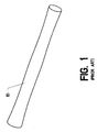
- FIG. 1 shows a prior art synthetic cable 10. It includes a bundle of strands. The strands are often woven or braided together. In other cases they are simply twisted or aligned in parallel. The reader will observe that the diameter of the cable fluctuates along its length. This effect is actually exaggerated in the view, so that it may more easily be observed. Such variations in diameter are quite significant when it comes time to place the cable into an anchor, however, since the anchor's internal diameter must generally fit snugly around the cable.
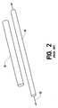
- FIG. 2 shows another phenomenon which is typical of synthetic cables.
- the upper cable 10 in the view is under no tension.
- the lower cable 10 has been placed under applied tension 12.
- the cable tends to elongate and the overall diameter tends to shrink.
- many synthetic fibers have a high tensile modulus, and do not elongate visibly under tension.
- the phenomenon shown in FIG. 2 does not represent the elongation of individual fibers. Rather, it results from the fact that the individual strands - which can be very flexible and very fine - do not remain well aligned when not under tension.
- FIG. 3 illustrates another problem inherent in the prior art.
- the two cables shown have different diameters.
- an anchor that is to be attached to such cables must have its internal dimensions matched to the diameter of the specific cable.
- the reader should understand that an appropriate and generally small clearance must exist between the passage through an anchor and the cable which is to be inserted in the anchor. There must be enough room to fit the components together, but not enough room to allow a misaligned or "sloppy" fit.
- an anchor which is particularly suited to a particular cable diameter must be available.
- the size of a cable is often optimized for a particular application. This will result in many different cable diameters. Traditionally, therefore, many different anchor sizes will be needed as well. While it is certainly possible to provide a large number of different anchor sizes, a more standardized solution is desirable.
- anchors used to create a complete and terminated cable are often a large percentage of the total cost. This is particularly true for low-volume, specialized anchors. Such anchors can comprise 70-95% of the total cost of the completed cable.
- a standardized and mass-produced anchor can be quite inexpensive - sometimes as little as 2% of the cost of a "custom" anchor. The reader will thereby appreciate the advantage of a method which allows a single anchor to be used over a range of cable sizes.
- the present invention comprises a method of applying a jacket of varying thickness around the exterior of a cable in order to make the cable's diameter both standard and uniform.
- "uniform” means devoid of fluctuations.
- "Standard” means conforming to a predetermined anchor size.
- the number of anchors needed to cover a range of cable diameters and types may thereby be greatly reduced.
- the method also allows the use of standardized cutting and processing equipment.
- a variety of techniques for applying the jacket are disclosed, including extruding, dipping, molding, and spraying.
- a portion of the jacket extends into the anchor to form the desired interface. In some applications, it may be desirable to remove the portion of the jacket lying outside the anchor or anchors once the terminations are in place. Once the termination is completed, it is also possible to remove the entire jacket.
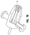
- FIG. 7 shows extruding head 42.
- a synthetic cable is fed through feed tube 88, ultimately passing out through cable orifice 80 in a direction toward the viewer.
- Plastic is fed into the device through a pair of plastic infeeds 44, after which it accumulates in plastic manifold 46.
- the plastic is in a molten state, having been heated and pressurized by suitable processing equipment (typically an auger feed).
- a sheath of jacket material is formed over the cable through jacket annulus 82.
- the jacket material solidifies on the cable, thereby creating a unified assembly.
- FIG. 7B shows an extruding head 42 in which jacket annulus 82 is mounted in jacket annulus insert 90.
- This insert can be removed from the extruding head and replaced with another insert having a different diameter.
- a production line might employ a set of jacket annulus inserts which are sized to produce jackets having thicknesses of approximately 0.005, 0.010, 0.015, 0.020, and 0.025 (Note that the thickness will actually vary over a single cable's length, since the cable's diameter varies.
- the extruding head ensures that the external diameter is uniform. Because the internal diameter varies with the varying cable diameter, the thickness may vary).
- Feed tube 88 can likewise be made removable so that cables of different sizes can be run through the same extruding head.
- FIG. 4 shows two cables which have had a jacket applied.
- the reader will observe that the two cables have different diameters.
- the lower cable in the view has had a thick jacket 14 applied, whereas the upper cable in the view has had a thin jacket 22 applied.
- the result is that the outside diameter of the two jackets is the same, even though they encase two cables having significantly different diameters.
- the external diameter of the two jacketed cables is the same, which is the important feature in the present context.
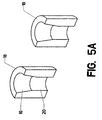
- FIG. 5A shows two anchors 18 sectioned in half in order to expose the internal features.
- a cable can be locked into such an anchor by placing the exposed cable strands through cylindrical bore 20 and splaying them outward within expanding cavity 16.
- Liquid potting compound is infused throughout the strands (either before or after they are placed within the expanding cavity). The liquid potting compound then solidifies, thereby locking the cable to the anchor and forming a completed "termination" (Again, the reader should bear in mind that methods other than potting are available for locking the strands within the anchor. The present invention can apply to these other methods as well).
- FIG. 5A the two anchors shown in FIG. 5A have identical dimensions. Under the prior art, this fact would means that they are suited to one and only one cable diameter.
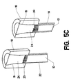
- FIG. 5B the two cables shown in FIG. 4 (with a portion of the jackets being removed to expose the end strands) have been placed into the two anchors 18 (still a sectional view). The exposed strands have been splayed within expanding cavity 16. Because the external diameter of the two jackets is the same, they both fit snugly within cylindrical bore 20.
- FIG. 5C shows the two assemblies after the potting compound has hardened to form potted regions 24.
- the strength of the termination is not significantly compromised by using this process, and may even be increased.
- the potting compound fills the gap resulting from the use of a smaller cable, thereby centering the strands within expanding cavity 16 (Assuming, of course, that the jacket application process is well controlled to center the strands within the external diameter of the jacket).
- the cable in its unjacketed state may fluctuate significantly in diameter and the individual strands may not be well-aligned.
- the addition of the jacket tends to reduce both these problems. Not only does it provide a desired overall diameter, it may often reduce the overall diameter by compacting the strands more closely together. It therefore produces more consistent and repeatable geometry.
- the cable on the right side of FIG. 5B has a diameter of 0.214 inches.
- the cable on the left has a diameter of 0.240 inches.
- Cylindrical bore 20 has a diameter of 0.250 inches.
- Thin jacket 22 is therefore extruded to a thickness of 0.005 inches whereas thick jacket 14 is extruded to a thickness of 0.018 inches (Note that the increase in diameter is twice the jacket thickness).
- an anchor having a bore of 0.250 can accommodate a cable having a diameter in the range of about 0.210 to 0.240.
- the jacket thickness is selected to increase the external diameter of the cable to the desired value.
- a second anchor can be provided having a cylindrical bore 20 measuring 0.300. Using jackets of varying thicknesses this second anchor could accommodate a cable having a diameter in the range of about 0.245 to 0.290.
- the table below gives one possible scenario for implementing the present inventive method in terminating cables having a diameter of 0.110 to 0.190 inches: Anchor Cyl. Bore Cable Diameter Jacket Thickness 0.150 0.110 0.020 0.150 0.120 0.015 0.150 0.130 0.010 0.150 0.140 0.005 0.200 0.150 0.025 0.200 0.160 0.020 0.200 0.170 0.015 0.200 0.180 0.010
- FIG. 6 shows a completed cable termination in a non-sectional view. Note that for this embodiment, the jacket has been removed except for the portion proximate the anchor.
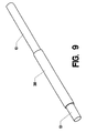
- FIG. 8 shows a jacket being added by a molding process. Cable 10 is clamped between upper mold 30 and lower mold 28, so that mold cavity 34 lies around the cable. Molten plastic is then fed in through jacket material feed 36. Once the jacket material solidifies, the mold is opened. FIG. 9 shows the result. A molded jacket 38 has been placed over a short length of cable 10.
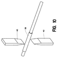
- FIG. 10 shows molded jacket 38 placed between a pair of opposing cutters 40. These close to cut the cable.
- FIG. 11 shows the same cable after it has been cut. The end facing the viewer can then have a small length of the jacket stripped away in preparation for the termination process. The length of jacket shown can serve the same purpose as for the jacket extruded over the entire length of the cable.
- FIG. 12 shows another approach to applying a jacket.
- Shrinkable jacket 84 which initially has an internal diameter greater than the cable, is slipped into the desired position. It is then shrunken over the cable - typically by a heating process. If the shrinkable jacket is carefully sized (including a suitable initial and final thickness) it can produce a finished jacket having the desired thickness. Its external diameter, however, tends to vary with the diameter of the underlying cable. Thus, a secondary operation is desirable.
- Jackets can also be applied over some or all of the cable by dipping or spraying. These processes tend to produce varying jacket thicknesses, as for the heat shrinking approach. Thus, secondary operations may be needed to produce the desired uniform external diameter for these as well.
- FIG. 13 shows one such secondary operation.
- a cable is being drawn through sizing die 50 (The die is sectioned in half to aid visualization).
- Enlarged jacket 54 - which possesses a varying diameter - is cut down to standard diameter jacket 52 (which possesses a uniform diameter).
- the jacket employed in the inventive process can be described as a "sizing jacket” since it effectively resizes the cable for use in a standard anchor.
- the term "sizing jacket” will be understood to mean a jacket having a carefully selected and uniform external diameter which conforms to the internal diameter of a standardized anchor (allowing for appropriate clearances).
- the portion of the jacket lying outside the anchor my optionally be removed by any desired method.
- the portion of the jcaket actually lying inside the anchor can be pulled free in some applications as well. In still other applications, it is advantageous to leave the entire jacket in place.
Landscapes
- Engineering & Computer Science (AREA)
- General Engineering & Computer Science (AREA)
- Mechanical Engineering (AREA)
- Ropes Or Cables (AREA)
- Processing Of Terminals (AREA)
Applications Claiming Priority (1)
| Application Number | Priority Date | Filing Date | Title |
|---|---|---|---|
| US10/933,048 US20060096089A1 (en) | 2004-09-02 | 2004-09-02 | Method for standardizing hardware for synthetic cables |
Publications (2)
| Publication Number | Publication Date |
|---|---|
| EP1632693A2 true EP1632693A2 (de) | 2006-03-08 |
| EP1632693A3 EP1632693A3 (de) | 2006-12-27 |
Family
ID=35445729
Family Applications (1)
| Application Number | Title | Priority Date | Filing Date |
|---|---|---|---|
| EP05255336A Withdrawn EP1632693A3 (de) | 2004-09-02 | 2005-08-31 | Verfahren zur Standardisierung von Ausrüstungen für synthetische Seile |
Country Status (2)
| Country | Link |
|---|---|
| US (1) | US20060096089A1 (de) |
| EP (1) | EP1632693A3 (de) |
Families Citing this family (9)
| Publication number | Priority date | Publication date | Assignee | Title |
|---|---|---|---|---|
| US10113296B2 (en) * | 2013-10-01 | 2018-10-30 | Bright Technologies, L.L.C. | Dragline bucket rigging system |
| US10434724B2 (en) * | 2014-01-31 | 2019-10-08 | Richard V. Campbell | Controlled translation method of affixing a termination to a tensile member |
| US9840044B2 (en) * | 2015-02-02 | 2017-12-12 | Richard V Campbell | Controlled translation method of affixing a termination to a tensile member |
| US10591022B2 (en) * | 2017-12-12 | 2020-03-17 | Bright Technologies, Llc | Controlled translation method of affixing a termination to a multi-stranded tensile member |
| US10563727B2 (en) * | 2017-12-12 | 2020-02-18 | Bright Technologies, Llc | Controlled translation method of affixing a termination to a tensile member |
| US10962088B2 (en) * | 2018-05-10 | 2021-03-30 | Richard V. Campbell | Potting neck enhancement |
| US11378159B2 (en) * | 2018-06-01 | 2022-07-05 | Bright Technologies, Llc | Wicking termination system |
| WO2020076677A1 (en) * | 2018-10-08 | 2020-04-16 | Campbell Richard V | Controlled translation method of affixing a termination to a tensile member |
| US10710143B2 (en) * | 2018-10-08 | 2020-07-14 | Bright Technologies, Llc | Controlled translation method of affixing a termination to a multi-stranded tensile member |
Family Cites Families (7)
| Publication number | Priority date | Publication date | Assignee | Title |
|---|---|---|---|---|
| US3507949A (en) * | 1968-06-11 | 1970-04-21 | British Ropes Ltd | Method of socketing strands |
| US3660887A (en) * | 1969-06-20 | 1972-05-09 | Nupla Corp | Method for connecting attachments to fiber glass rods |
| DE3302788A1 (de) * | 1983-01-28 | 1984-08-16 | Rosenthal Technik Ag, 8672 Selb | Abdichtung zwischen metallarmatur und glasfaserstab bei hochspannungs-verbundisolatoren |
| US4500747A (en) * | 1983-03-30 | 1985-02-19 | Northern Telecom Limited | Gas pressurizable cable with compressed plug seal and method of making it |
| JPS63120941A (ja) * | 1986-11-10 | 1988-05-25 | Meito Denki Koji Kk | 線条体の端末部の構造 |
| US5415490A (en) * | 1993-07-13 | 1995-05-16 | Flory; John F. | Rope termination with constant-cross-section, divided-cavity potted socket |
| US7237336B2 (en) * | 2002-08-21 | 2007-07-03 | Bright Technologies, Llc | Cable manufacturing method |
-
2004
- 2004-09-02 US US10/933,048 patent/US20060096089A1/en not_active Abandoned
-
2005
- 2005-08-31 EP EP05255336A patent/EP1632693A3/de not_active Withdrawn
Also Published As
| Publication number | Publication date |
|---|---|
| EP1632693A3 (de) | 2006-12-27 |
| US20060096089A1 (en) | 2006-05-11 |
Similar Documents
| Publication | Publication Date | Title |
|---|---|---|
| US7237336B2 (en) | Cable manufacturing method | |
| DE3788245T2 (de) | Optisches Kabel. | |
| US4710594A (en) | Telecommunications cable | |
| GB2310294A (en) | Producing a reinforced optical cable by extrusion | |
| EP1632693A2 (de) | Verfahren zur Standardisierung von Ausrüstungen für synthetische Seile | |
| DE10023208A1 (de) | Isolierung von Statorwicklungen im Spritzgussverfahren | |
| EP1154543A2 (de) | Isolierung von Statorwicklungen durch Schrumpfschläuche | |
| US5830304A (en) | Method for producing a tension-resistance core element for a cable | |
| DE2607058A1 (de) | Verfahren und form zum herstellen von geformten kabel-spleisstellen | |
| DE3243298A1 (de) | Verfahren und vorrichtung zur herstellung eines faseroptikkabels fuer die nachrichtenuebertragung | |
| US5151143A (en) | Moisture-impermeable electric conductor | |
| DE2735476C2 (de) | Verfahren und Vorrichtung zur Herstellung von Kabeln und Leitungen mit SZ-verseilten Verseilelementen | |
| DE3636927C2 (de) | ||
| DE10225879B4 (de) | Verfahren zum wasserdichten Abschliessen eines Kabelbaums | |
| WO1996016415A1 (de) | Verfahren und vorrichtung zum abschnittsweisen ummanteln von eine vielzahl von adern aufweisenden verdrahtungssystemen mit kunststoff | |
| DE3026999C2 (de) | SZ-verseiltes, mehradriges elektrisches Energiekabel | |
| US6296725B1 (en) | High frequency ribbon cable for twist capsule cable applications | |
| EP1589543B1 (de) | Leitungseinführung und Verfahren zu deren Herstellung | |
| DE2802127C2 (de) | ||
| EP0430867A1 (de) | Schwachstrom-Freileitungskabel mit parallelen Adern | |
| US6217809B1 (en) | Methods for splicing dielectric strength tapes utilized in communication cables | |
| EP1453651B1 (de) | Verfahren zur isolierung von statorwicklungen | |
| DE102004061353B3 (de) | Verfahren und Vorrichtung zur Herstellung eines Mehrleiterkabels | |
| JPH0318210A (ja) | テンションメンバに有機新素材を用いた架空配電線の接続方法 | |
| DE10213736C1 (de) | Verfahren und Vorrichtung zur Herstellung von Flachbandkabeln |
Legal Events
| Date | Code | Title | Description |
|---|---|---|---|
| PUAI | Public reference made under article 153(3) epc to a published international application that has entered the european phase |
Free format text: ORIGINAL CODE: 0009012 |
|
| AK | Designated contracting states |
Kind code of ref document: A2 Designated state(s): AT BE BG CH CY CZ DE DK EE ES FI FR GB GR HU IE IS IT LI LT LU LV MC NL PL PT RO SE SI SK TR |
|
| AX | Request for extension of the european patent |
Extension state: AL BA HR MK YU |
|
| PUAL | Search report despatched |
Free format text: ORIGINAL CODE: 0009013 |
|
| AK | Designated contracting states |
Kind code of ref document: A3 Designated state(s): AT BE BG CH CY CZ DE DK EE ES FI FR GB GR HU IE IS IT LI LT LU LV MC NL PL PT RO SE SI SK TR |
|
| AX | Request for extension of the european patent |
Extension state: AL BA HR MK YU |
|
| AKX | Designation fees paid | ||
| REG | Reference to a national code |
Ref country code: DE Ref legal event code: 8566 |
|
| STAA | Information on the status of an ep patent application or granted ep patent |
Free format text: STATUS: THE APPLICATION IS DEEMED TO BE WITHDRAWN |
|
| 18D | Application deemed to be withdrawn |
Effective date: 20070628 |