EP1632653B1 - Kühlwasserkanal in einem Zylinderkopf - Google Patents
Kühlwasserkanal in einem Zylinderkopf Download PDFInfo
- Publication number
- EP1632653B1 EP1632653B1 EP04021096A EP04021096A EP1632653B1 EP 1632653 B1 EP1632653 B1 EP 1632653B1 EP 04021096 A EP04021096 A EP 04021096A EP 04021096 A EP04021096 A EP 04021096A EP 1632653 B1 EP1632653 B1 EP 1632653B1
- Authority
- EP
- European Patent Office
- Prior art keywords
- cooling water
- cylinder head
- passage
- engine
- cylinder
- Prior art date
- Legal status (The legal status is an assumption and is not a legal conclusion. Google has not performed a legal analysis and makes no representation as to the accuracy of the status listed.)
- Expired - Lifetime
Links
- 239000000498 cooling water Substances 0.000 title claims abstract description 73
- 125000006850 spacer group Chemical group 0.000 claims abstract description 11
- 238000002485 combustion reaction Methods 0.000 claims description 9
- 238000005266 casting Methods 0.000 claims description 3
- 238000001816 cooling Methods 0.000 abstract description 26
- XLYOFNOQVPJJNP-UHFFFAOYSA-N water Substances O XLYOFNOQVPJJNP-UHFFFAOYSA-N 0.000 abstract 1
- 239000000446 fuel Substances 0.000 description 7
- 239000000203 mixture Substances 0.000 description 6
- 238000010276 construction Methods 0.000 description 4
- 230000017525 heat dissipation Effects 0.000 description 4
- 238000010521 absorption reaction Methods 0.000 description 3
- 239000002912 waste gas Substances 0.000 description 2
- 235000004522 Pentaglottis sempervirens Nutrition 0.000 description 1
- 230000006835 compression Effects 0.000 description 1
- 238000007906 compression Methods 0.000 description 1
- 239000007789 gas Substances 0.000 description 1
- 238000012856 packing Methods 0.000 description 1
Images


Classifications
-
- F—MECHANICAL ENGINEERING; LIGHTING; HEATING; WEAPONS; BLASTING
- F02—COMBUSTION ENGINES; HOT-GAS OR COMBUSTION-PRODUCT ENGINE PLANTS
- F02F—CYLINDERS, PISTONS OR CASINGS, FOR COMBUSTION ENGINES; ARRANGEMENTS OF SEALINGS IN COMBUSTION ENGINES
- F02F1/00—Cylinders; Cylinder heads
- F02F1/24—Cylinder heads
- F02F1/26—Cylinder heads having cooling means
- F02F1/36—Cylinder heads having cooling means for liquid cooling
- F02F1/40—Cylinder heads having cooling means for liquid cooling cylinder heads with means for directing, guiding, or distributing liquid stream
-
- F—MECHANICAL ENGINEERING; LIGHTING; HEATING; WEAPONS; BLASTING
- F01—MACHINES OR ENGINES IN GENERAL; ENGINE PLANTS IN GENERAL; STEAM ENGINES
- F01L—CYCLICALLY OPERATING VALVES FOR MACHINES OR ENGINES
- F01L1/00—Valve-gear or valve arrangements, e.g. lift-valve gear
- F01L1/02—Valve drive
- F01L1/04—Valve drive by means of cams, camshafts, cam discs, eccentrics or the like
- F01L1/047—Camshafts
- F01L1/053—Camshafts overhead type
- F01L2001/0537—Double overhead camshafts [DOHC]
Definitions
- the present invention is related to a cooling water passage, and more particularly, to a construction of a cooling water passage applied to the cylinder head of an engine.
- Motor vehicles including motorcycles and all-terrain vehicles among others operate by introducing fresh air to mix with fuel.
- the air-fuel mixture is then injected into engine to be ignited and exploded to produce motive power to push piston to engage in reciprocal motion for the crankshaft to drive belt gearshift mechanism to transmit the motive power.
- Air-cooling engine and water-cooling engine are available depending on the way of heat dissipation.
- a water-cooling engine is usually selected for a larger vehicle.
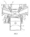
- a water-cooling engine 1 of the prior art as illustrated in Fig. 1 of the accompanying drawings is essentially comprised of a cylinder 11, a cylinder head 12, a piston 13, and a valve mechanism 14.
- the cylinder head 12 is provided on the top of the cylinder and contains an air inlet passage 121 and an exhaust passage 122.
- the cylinder 11 containing a cooling water passage 111 and a cooling water outlet 123 is provided to the cylinder head 12.
- the cylinder head 12 contains a combustion chamber 15 wherein the air-fuel mixture undergoes instantaneous combustion in the course of compression travel.
- the valve mechanism 14 is provided with an air inlet valve 141 and an exhaust valve 142, and the diameter of the air inlet valve 141 is usually made slightly greater than that of the exhaust valve 142.
- the air-fuel mixture upon entering into the combustion chamber 15 is ignited by an ignition member, i.e. the spark plug, and exploded.
- the gas pressure of the expansion pushes the piston 13 to engage in vertically reciprocal motion.
- the air inlet valve 141 is opened up to introduce the air-fuel mixture into the combustion chamber 15 for combustion and the resultant waste gas is fast discharge out of the exhaust valve 142 while the crankshaft drives the belt gearshift mechanism to operate (not illustrated), thus driving the rear wheels for the vehicle to move forward.
- the way of cooling in the cylinder head 12 of the water-cooling engine 1 of the prior art works by having the cooling water to flow from the cooling water passage 111 into the cylinder head 12 when the engine 1 is running.
- the cylinder head 12 is provided with a cooling water passage A around the valve mechanism as indicated by the arrow.
- the cooling water flows from both sides of the cooling water passage 111 in the cylinder 11 into the cooling water passage A in the cylinder head 12, the cooling water flows upward from the cooling water passage A; and the cooling water passes through the cooling water passage A between the air inlet valve 141 and the exhaust valve 142 to exit from a cooling water outlet 123 provided to the cylinder head 12 to complete a cooling cycle in the cylinder head 12 to absorb heat at high temperature produced as the engine runs for achieving the cooling effects.
- the newly introduced air-fuel mixture constantly cools down the temperature of the air inlet valve 141 while the exhaust valve 142 is continuously exposed to the waste gas at higher temperature. Therefore, the temperature readings respectively measured at both valves 141 and 142 are not the same. Furthermore, the cooling water passage A of a water-cooling engine of the prior art enters at the same time where it surrounds the valve mechanism 14 of the cylinder head 12.
- the water-cooling construction of the water-cooling engine 1 of the prior art is essentially comprised of having the cooling water passage entering from both sides into the cylinder head 12 and dispersing around the valve mechanism 14, resulting in inconsistent heat absorption of the cooling water between the cooling water passage A located on the side of the air inlet passage 121 and that on the side of the exhaust passage 122 when the cooling water flows up to exit from the cooling water passage A.
- the poor cooling consistency due to the excessive temperature difference between the air inlet valve 141 and the exhaust valve 142 subjects the mechanical parts of the engine to deformation.
- US-A-3 115 125 discloses an internal combustion engine cooling system for more efficiently cooling certain areas of the combustion chambers thereof.
- the US-A-3 115 125 reference fails to teach or disclose using a retainer to make the cooling water first cool the exhaust passage side at a higher temperature before cooling the air inlet passage side at a lower temperature.
- the primary purpose of the present invention is to provide a construction of cooling water passage in the cylinder head of an engine to upgrade the cooling effects for the cylinder head as a whole to avoid deformed mechanical parts due to inconsistent heat dissipation.
- a spacer is provided between the cylinder and the cylinder head.
- the spacer has a port connecting through the cooling water disposed on the side of the exhaust passage.
- the cooling water flowing from the cooling water connection port into the cylinder head is limited by a retainer thus to extend the flow route for the cooling water.
- the cooling water first cools the exhaust passage side at a higher temperature before cooling the air inlet passage side at a lower temperature thus evenly absorbing the heat at high temperature produced on the cylinder head as the engine runs.
- a cooling water inlet 211 and a waterway 212 for circulation of the cooling water are provided to the cylinder 21.
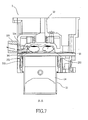
- the engine 2 includes the cylinder 21, and a cylinder head 22 on top of the cylinder 21.
- the cylinder head 22 contains an air inlet passage 221, an exhaust passage 222 to discharge the exhaust, a combustion chamber 23 where the air-fuel mixture is combusted, a piston 24 to engage in reciprocal motion inside the cylinder 21, and a valve mechanism seat 25 to accommodate multiple valves.
- a spacer 26 is provided between the cylinder 21 and the cylinder head of the engine 2, wherein a cooling-water outlet 223 (as illustrated in Fig. 7 ) to discharge the cooling water is provided to the cylinder head 22.
- the valve mechanism seat 25 is comprised of an air inlet valve seat 251 and an exhaust valve seat 252.
- a port 261 connecting through the cooling water is provided to the spacer 26 on the side of the exhaust passage 222.
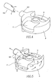
- Fig. 5 is a schematic view showing the spatial configuration of a cooling water passage B in the cylinder head 22 of the present invention.
- a retainer 224 which is a hollow pipe is provided to the cooling water outlet 223 and has one end provided with a gap a, and a limitation piece b in relation to the gap a.
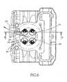
- the cooling water flows from the cooling water inlet 211 in the cylinder 21 into the waterway of the cylinder 21 when the engine 2 runs.
- the cooling water flowing into the waterway 212 flows upward to arrive at the spacer 26 where the cooling water will flow into the cylinder head 22 through the port 261 provided on the side of the exhaust passage 222 due to the packing status created between the cylinder 21 and the cylinder head 22 by the spacer 26.
- the retainer 224 is inserted to the cooling water outlet 223 of the cylinder head 22, the cooling water is frustrated by the limitation piece b extending from the retainer 224 when the cooling water flows from the port 261 into the cylinder head 22. Accordingly, the cooling water is forced to first pass through an exhaust passage side C at higher temperature before flowing through an air inlet passage side D to finally exit from the cooling water outlet 223.
- the cooling water as separated by the retainer 224 upon flowing into the cylinder head 22 through the cooling water connection port 261 of the spacer 26 passes by the exhaust valve seat 252 on the exhaust passage side C at higher temperature before passing by the air inlet valve 251 on the air inlet passage side D at lower temperature before exiting from the retainer 224 inserted to the cooling water outlet 223 to complete the cooling cycle.
- the cooling water by cooling first the exhaust passage side C at higher temperature before cooling the air inlet passage side D at lower temperature consistently absorbs the heat at high temperature produced on the cylinder head 22 while the engine 2 is running to achieve the results of reducing the temperature of the cylinder head 22, thus the engine 2.
- the retainer 224 may be forthwith casted to the cylinder head 22 during the casting process of the cylinder head 22 as illustrated in Fig. 7 ; or alternatively, the retainer 224 is fixed in the cooling water outlet 223 upon the completion of the casting process of the cylinder head 22.
- the construction of a cooling water passage for the cylinder head of engine disclosed in the present invention corrects the flaw of failing to provide consistent temperature reduction of the prior art by providing the retainer 224 at the cooling water outlet 223 of the cylinder head 22, extending the flow route for the cooling water and for the cooling water to cool first the exhaust passage side C at a higher temperature before cooling the air inlet passage side D at a lower temperature to consistently absorb the heat at high temperature produced to the cylinder head while the engine is running, thus upgrading heat dissipation results for the cylinder head as a whole and avoiding deformation to mechanical parts due to inconsistent heat absorption.
Landscapes
- Engineering & Computer Science (AREA)
- Chemical & Material Sciences (AREA)
- Combustion & Propulsion (AREA)
- Mechanical Engineering (AREA)
- General Engineering & Computer Science (AREA)
- Cylinder Crankcases Of Internal Combustion Engines (AREA)
- Apparatus For Radiation Diagnosis (AREA)
- Paper (AREA)
Claims (4)
- Ein Kühlwasserkanal in einem Motor (2), mit dem Motor bestehend aus einem Zylinder (21), einem Zylinderkopf (22) auf der Oberseite des Zylinders (21), einer Distanzscheibe (26) befindlich zwischen Zylinder (21) und Zylinderkopf (22), einem Lufteinlaßkanal (221) im Zylinderkopf (22), einem Abluftkanal (222), einem Verbrennungsraum (23) worin der Kühlwasserkanal mit einem Anschluß (261) versehen ist, um eine Kühlwasserzufuhr auf der Seite des Abluftkanals (222) anzuschließen, Kühlwasser das durch den Anschluß (261) in den Zylinderkopf (22) fließt wird behindert durch eine Führung (224), wodurch das Kühlwasser gezwungen wird, erst durch die Abluftseite (C) mit einer höhere Temperatur zu fließen bevor es durch die Lufteinlaßseite (D) fließt und schließlich aus dem Kühlwasserabfluß austritt, wobei die Führung (224) gebildet wird aus einem hohlen Rohr, dessen eine Seite aus einer Aussparung (a) und einem Begrenz-Lingsstück (b) in Bezug zur Aussparung (a) besteht.
- Der Kühlwasserkanal in einem Motor (2) aus Anspruch 1, wobei die Führung (224) direkt in den Zylinderkopf (22) gegossen ist.
- Der Kühlwasserkanal in einem Motor (2) aus Anspruch 1, wobei die Führung (224) im Kühlwasseraustritt (223) fest verankert ist als Ergebnis des Gießprozesses des Zylinderkopfs (22).
- Der Kühlwasserkanal in einem Motor (2) aus Anspruch 1, wobei das Kühlwasser zuerst ein en Abluftventilsitz (25) passiert, der sich auf der Seite des Abluftkanals befindet, bevor es zu einem Lufteinlaßventilsitz fließt, der sich auf der Seite des Lufteinlaßkanals befindet.
Priority Applications (4)
| Application Number | Priority Date | Filing Date | Title |
|---|---|---|---|
| DE602004031421T DE602004031421D1 (de) | 2004-09-04 | 2004-09-04 | Kühlwasserkanal in einem Zylinderkopf |
| EP04021096A EP1632653B1 (de) | 2004-09-04 | 2004-09-04 | Kühlwasserkanal in einem Zylinderkopf |
| AT04021096T ATE498763T1 (de) | 2004-09-04 | 2004-09-04 | Kühlwasserkanal in einem zylinderkopf |
| ES04021096T ES2358326T3 (es) | 2004-09-04 | 2004-09-04 | Conducto de agua de refrigeración de una culata de motor. |
Applications Claiming Priority (1)
| Application Number | Priority Date | Filing Date | Title |
|---|---|---|---|
| EP04021096A EP1632653B1 (de) | 2004-09-04 | 2004-09-04 | Kühlwasserkanal in einem Zylinderkopf |
Publications (2)
| Publication Number | Publication Date |
|---|---|
| EP1632653A1 EP1632653A1 (de) | 2006-03-08 |
| EP1632653B1 true EP1632653B1 (de) | 2011-02-16 |
Family
ID=34926430
Family Applications (1)
| Application Number | Title | Priority Date | Filing Date |
|---|---|---|---|
| EP04021096A Expired - Lifetime EP1632653B1 (de) | 2004-09-04 | 2004-09-04 | Kühlwasserkanal in einem Zylinderkopf |
Country Status (4)
| Country | Link |
|---|---|
| EP (1) | EP1632653B1 (de) |
| AT (1) | ATE498763T1 (de) |
| DE (1) | DE602004031421D1 (de) |
| ES (1) | ES2358326T3 (de) |
Families Citing this family (3)
| Publication number | Priority date | Publication date | Assignee | Title |
|---|---|---|---|---|
| US8539929B2 (en) * | 2009-11-18 | 2013-09-24 | Harley-Davidson Motor Company | Cylinder head cooling system |
| GB2511136B (en) * | 2013-02-26 | 2019-12-04 | Mclaren Automotive Ltd | Engine cooling |
| CN113236434A (zh) * | 2021-04-27 | 2021-08-10 | 重庆隆鑫机车有限公司 | 冷却水套及发动机 |
Family Cites Families (6)
| Publication number | Priority date | Publication date | Assignee | Title |
|---|---|---|---|---|
| US2077224A (en) * | 1931-06-26 | 1937-04-13 | Gen Electric | Combustion engine |
| US3115125A (en) | 1961-09-25 | 1963-12-24 | Charles O Spencer | Internal combustion engine cooling system |
| US3155084A (en) * | 1962-03-28 | 1964-11-03 | Caterpillar Tractor Co | Cooling means for internal combustion engines |
| JPH04255554A (ja) * | 1991-02-06 | 1992-09-10 | Suzuki Motor Corp | 四サイクルエンジンのシリンダーヘッド冷却装置 |
| JPH11229955A (ja) * | 1998-02-13 | 1999-08-24 | Daihatsu Motor Co Ltd | 内燃機関におけるシリンダヘッドの構造 |
| DE20216452U1 (de) * | 2002-10-25 | 2002-12-19 | FEV Motorentechnik GmbH, 52078 Aachen | Zylinderkopf für eine wassergekühlte Kolbenbrennkraftmaschine mit Innenversteifung |
-
2004
- 2004-09-04 ES ES04021096T patent/ES2358326T3/es not_active Expired - Lifetime
- 2004-09-04 AT AT04021096T patent/ATE498763T1/de not_active IP Right Cessation
- 2004-09-04 DE DE602004031421T patent/DE602004031421D1/de not_active Expired - Lifetime
- 2004-09-04 EP EP04021096A patent/EP1632653B1/de not_active Expired - Lifetime
Also Published As
| Publication number | Publication date |
|---|---|
| ES2358326T3 (es) | 2011-05-09 |
| DE602004031421D1 (de) | 2011-03-31 |
| ATE498763T1 (de) | 2011-03-15 |
| EP1632653A1 (de) | 2006-03-08 |
Similar Documents
| Publication | Publication Date | Title |
|---|---|---|
| CN203009061U (zh) | 发动机冷却系统 | |
| WO2001065092A1 (en) | Four stroke engine with cooling system | |
| US20160252007A1 (en) | Pre-chamber assembly for engine | |
| EP3499002B1 (de) | Motorkühlsystem für fahrzeuge | |
| US10145333B2 (en) | Cylinder head integrated with exhaust manifold and EGR cooler | |
| US20090260588A1 (en) | Cylinder head | |
| EP1632653B1 (de) | Kühlwasserkanal in einem Zylinderkopf | |
| JP4559503B2 (ja) | 燃料噴射弁の冷却装置 | |
| KR20090103405A (ko) | 자동차용 egr 쿨러 | |
| JP2006342799A (ja) | 内燃機関 | |
| CN109026322B (zh) | 发动机的冷却用油通路构造 | |
| JPS5835221A (ja) | 内燃機関の冷却装置 | |
| JP4486477B2 (ja) | エンジンのシリンダーヘッドの冷却水通路構造 | |
| CN115539236A (zh) | 发动机总成及暖机系统 | |
| CN115523047A (zh) | 发动机总成 | |
| JP2006348958A (ja) | 内燃機関の排気還流装置 | |
| CN109026321B (zh) | 发动机的冷却用油通路构造 | |
| WO2015194143A1 (ja) | エンジン冷却システム | |
| KR101004255B1 (ko) | 자동차용 egr 및 스월시스템 통합 인테이크 메니폴드 | |
| US7082900B2 (en) | Outboard engine system | |
| WO2025134416A1 (ja) | エンジン | |
| JP2004332656A (ja) | 副燃焼室式ディーゼルエンジン | |
| JPH02119611A (ja) | 4サイクルエンジンの冷却装置 | |
| KR20020023572A (ko) | 실린더헤드의 냉각수 분사장치 | |
| KR19980038566A (ko) | 공냉과 수냉을 겸한 인터쿨러 |
Legal Events
| Date | Code | Title | Description |
|---|---|---|---|
| PUAI | Public reference made under article 153(3) epc to a published international application that has entered the european phase |
Free format text: ORIGINAL CODE: 0009012 |
|
| AK | Designated contracting states |
Kind code of ref document: A1 Designated state(s): AT BE BG CH CY CZ DE DK EE ES FI FR GB GR HU IE IT LI LU MC NL PL PT RO SE SI SK TR |
|
| AX | Request for extension of the european patent |
Extension state: AL HR LT LV MK |
|
| 17P | Request for examination filed |
Effective date: 20060904 |
|
| AKX | Designation fees paid |
Designated state(s): AT BE BG CH CY CZ DE DK EE ES FI FR GB GR HU IE IT LI LU MC NL PL PT RO SE SI SK TR |
|
| 17Q | First examination report despatched |
Effective date: 20081106 |
|
| GRAP | Despatch of communication of intention to grant a patent |
Free format text: ORIGINAL CODE: EPIDOSNIGR1 |
|
| GRAS | Grant fee paid |
Free format text: ORIGINAL CODE: EPIDOSNIGR3 |
|
| GRAA | (expected) grant |
Free format text: ORIGINAL CODE: 0009210 |
|
| AK | Designated contracting states |
Kind code of ref document: B1 Designated state(s): AT BE BG CH CY CZ DE DK EE ES FI FR GB GR HU IE IT LI LU MC NL PL PT RO SE SI SK TR |
|
| REG | Reference to a national code |
Ref country code: GB Ref legal event code: FG4D |
|
| REG | Reference to a national code |
Ref country code: CH Ref legal event code: EP |
|
| REG | Reference to a national code |
Ref country code: IE Ref legal event code: FG4D |
|
| REF | Corresponds to: |
Ref document number: 602004031421 Country of ref document: DE Date of ref document: 20110331 Kind code of ref document: P |
|
| REG | Reference to a national code |
Ref country code: DE Ref legal event code: R096 Ref document number: 602004031421 Country of ref document: DE Effective date: 20110331 |
|
| REG | Reference to a national code |
Ref country code: ES Ref legal event code: FG2A Ref document number: 2358326 Country of ref document: ES Kind code of ref document: T3 Effective date: 20110426 |
|
| REG | Reference to a national code |
Ref country code: NL Ref legal event code: VDEP Effective date: 20110216 |
|
| PG25 | Lapsed in a contracting state [announced via postgrant information from national office to epo] |
Ref country code: SE Free format text: LAPSE BECAUSE OF FAILURE TO SUBMIT A TRANSLATION OF THE DESCRIPTION OR TO PAY THE FEE WITHIN THE PRESCRIBED TIME-LIMIT Effective date: 20110216 Ref country code: PT Free format text: LAPSE BECAUSE OF FAILURE TO SUBMIT A TRANSLATION OF THE DESCRIPTION OR TO PAY THE FEE WITHIN THE PRESCRIBED TIME-LIMIT Effective date: 20110616 Ref country code: GR Free format text: LAPSE BECAUSE OF FAILURE TO SUBMIT A TRANSLATION OF THE DESCRIPTION OR TO PAY THE FEE WITHIN THE PRESCRIBED TIME-LIMIT Effective date: 20110517 |
|
| PG25 | Lapsed in a contracting state [announced via postgrant information from national office to epo] |
Ref country code: BE Free format text: LAPSE BECAUSE OF FAILURE TO SUBMIT A TRANSLATION OF THE DESCRIPTION OR TO PAY THE FEE WITHIN THE PRESCRIBED TIME-LIMIT Effective date: 20110216 Ref country code: CY Free format text: LAPSE BECAUSE OF FAILURE TO SUBMIT A TRANSLATION OF THE DESCRIPTION OR TO PAY THE FEE WITHIN THE PRESCRIBED TIME-LIMIT Effective date: 20110216 Ref country code: AT Free format text: LAPSE BECAUSE OF FAILURE TO SUBMIT A TRANSLATION OF THE DESCRIPTION OR TO PAY THE FEE WITHIN THE PRESCRIBED TIME-LIMIT Effective date: 20110216 Ref country code: NL Free format text: LAPSE BECAUSE OF FAILURE TO SUBMIT A TRANSLATION OF THE DESCRIPTION OR TO PAY THE FEE WITHIN THE PRESCRIBED TIME-LIMIT Effective date: 20110216 Ref country code: PL Free format text: LAPSE BECAUSE OF FAILURE TO SUBMIT A TRANSLATION OF THE DESCRIPTION OR TO PAY THE FEE WITHIN THE PRESCRIBED TIME-LIMIT Effective date: 20110216 Ref country code: SI Free format text: LAPSE BECAUSE OF FAILURE TO SUBMIT A TRANSLATION OF THE DESCRIPTION OR TO PAY THE FEE WITHIN THE PRESCRIBED TIME-LIMIT Effective date: 20110216 Ref country code: FI Free format text: LAPSE BECAUSE OF FAILURE TO SUBMIT A TRANSLATION OF THE DESCRIPTION OR TO PAY THE FEE WITHIN THE PRESCRIBED TIME-LIMIT Effective date: 20110216 Ref country code: BG Free format text: LAPSE BECAUSE OF FAILURE TO SUBMIT A TRANSLATION OF THE DESCRIPTION OR TO PAY THE FEE WITHIN THE PRESCRIBED TIME-LIMIT Effective date: 20110516 |
|
| PG25 | Lapsed in a contracting state [announced via postgrant information from national office to epo] |
Ref country code: DK Free format text: LAPSE BECAUSE OF FAILURE TO SUBMIT A TRANSLATION OF THE DESCRIPTION OR TO PAY THE FEE WITHIN THE PRESCRIBED TIME-LIMIT Effective date: 20110216 Ref country code: EE Free format text: LAPSE BECAUSE OF FAILURE TO SUBMIT A TRANSLATION OF THE DESCRIPTION OR TO PAY THE FEE WITHIN THE PRESCRIBED TIME-LIMIT Effective date: 20110216 |
|
| PG25 | Lapsed in a contracting state [announced via postgrant information from national office to epo] |
Ref country code: RO Free format text: LAPSE BECAUSE OF FAILURE TO SUBMIT A TRANSLATION OF THE DESCRIPTION OR TO PAY THE FEE WITHIN THE PRESCRIBED TIME-LIMIT Effective date: 20110216 Ref country code: SK Free format text: LAPSE BECAUSE OF FAILURE TO SUBMIT A TRANSLATION OF THE DESCRIPTION OR TO PAY THE FEE WITHIN THE PRESCRIBED TIME-LIMIT Effective date: 20110216 Ref country code: CZ Free format text: LAPSE BECAUSE OF FAILURE TO SUBMIT A TRANSLATION OF THE DESCRIPTION OR TO PAY THE FEE WITHIN THE PRESCRIBED TIME-LIMIT Effective date: 20110216 |
|
| PLBE | No opposition filed within time limit |
Free format text: ORIGINAL CODE: 0009261 |
|
| STAA | Information on the status of an ep patent application or granted ep patent |
Free format text: STATUS: NO OPPOSITION FILED WITHIN TIME LIMIT |
|
| 26N | No opposition filed |
Effective date: 20111117 |
|
| REG | Reference to a national code |
Ref country code: DE Ref legal event code: R097 Ref document number: 602004031421 Country of ref document: DE Effective date: 20111117 |
|
| PG25 | Lapsed in a contracting state [announced via postgrant information from national office to epo] |
Ref country code: MC Free format text: LAPSE BECAUSE OF NON-PAYMENT OF DUE FEES Effective date: 20110930 |
|
| REG | Reference to a national code |
Ref country code: CH Ref legal event code: PL |
|
| GBPC | Gb: european patent ceased through non-payment of renewal fee |
Effective date: 20110904 |
|
| REG | Reference to a national code |
Ref country code: IE Ref legal event code: MM4A |
|
| PG25 | Lapsed in a contracting state [announced via postgrant information from national office to epo] |
Ref country code: IE Free format text: LAPSE BECAUSE OF NON-PAYMENT OF DUE FEES Effective date: 20110904 Ref country code: LI Free format text: LAPSE BECAUSE OF NON-PAYMENT OF DUE FEES Effective date: 20110930 Ref country code: CH Free format text: LAPSE BECAUSE OF NON-PAYMENT OF DUE FEES Effective date: 20110930 |
|
| PG25 | Lapsed in a contracting state [announced via postgrant information from national office to epo] |
Ref country code: GB Free format text: LAPSE BECAUSE OF NON-PAYMENT OF DUE FEES Effective date: 20110904 |
|
| PG25 | Lapsed in a contracting state [announced via postgrant information from national office to epo] |
Ref country code: LU Free format text: LAPSE BECAUSE OF NON-PAYMENT OF DUE FEES Effective date: 20110904 |
|
| PG25 | Lapsed in a contracting state [announced via postgrant information from national office to epo] |
Ref country code: TR Free format text: LAPSE BECAUSE OF FAILURE TO SUBMIT A TRANSLATION OF THE DESCRIPTION OR TO PAY THE FEE WITHIN THE PRESCRIBED TIME-LIMIT Effective date: 20110216 |
|
| PG25 | Lapsed in a contracting state [announced via postgrant information from national office to epo] |
Ref country code: HU Free format text: LAPSE BECAUSE OF FAILURE TO SUBMIT A TRANSLATION OF THE DESCRIPTION OR TO PAY THE FEE WITHIN THE PRESCRIBED TIME-LIMIT Effective date: 20110216 |
|
| REG | Reference to a national code |
Ref country code: FR Ref legal event code: PLFP Year of fee payment: 13 |
|
| REG | Reference to a national code |
Ref country code: FR Ref legal event code: PLFP Year of fee payment: 14 |
|
| REG | Reference to a national code |
Ref country code: FR Ref legal event code: PLFP Year of fee payment: 15 |
|
| PGFP | Annual fee paid to national office [announced via postgrant information from national office to epo] |
Ref country code: IT Payment date: 20180925 Year of fee payment: 15 Ref country code: FR Payment date: 20180924 Year of fee payment: 15 Ref country code: DE Payment date: 20180828 Year of fee payment: 15 |
|
| PGFP | Annual fee paid to national office [announced via postgrant information from national office to epo] |
Ref country code: ES Payment date: 20181022 Year of fee payment: 15 |
|
| REG | Reference to a national code |
Ref country code: DE Ref legal event code: R119 Ref document number: 602004031421 Country of ref document: DE |
|
| PG25 | Lapsed in a contracting state [announced via postgrant information from national office to epo] |
Ref country code: DE Free format text: LAPSE BECAUSE OF NON-PAYMENT OF DUE FEES Effective date: 20200401 |
|
| PG25 | Lapsed in a contracting state [announced via postgrant information from national office to epo] |
Ref country code: IT Free format text: LAPSE BECAUSE OF NON-PAYMENT OF DUE FEES Effective date: 20190904 |
|
| PG25 | Lapsed in a contracting state [announced via postgrant information from national office to epo] |
Ref country code: FR Free format text: LAPSE BECAUSE OF NON-PAYMENT OF DUE FEES Effective date: 20190930 |
|
| REG | Reference to a national code |
Ref country code: ES Ref legal event code: FD2A Effective date: 20210127 |
|
| PG25 | Lapsed in a contracting state [announced via postgrant information from national office to epo] |
Ref country code: ES Free format text: LAPSE BECAUSE OF NON-PAYMENT OF DUE FEES Effective date: 20190905 |