EP1632643B1 - Verfahren und Vorrichtung zum Erfassen und Aufzeichnen der Einsatzbedingungen eines Bohrmeissels während des Bohrens - Google Patents
Verfahren und Vorrichtung zum Erfassen und Aufzeichnen der Einsatzbedingungen eines Bohrmeissels während des Bohrens Download PDFInfo
- Publication number
- EP1632643B1 EP1632643B1 EP05077687A EP05077687A EP1632643B1 EP 1632643 B1 EP1632643 B1 EP 1632643B1 EP 05077687 A EP05077687 A EP 05077687A EP 05077687 A EP05077687 A EP 05077687A EP 1632643 B1 EP1632643 B1 EP 1632643B1
- Authority
- EP
- European Patent Office
- Prior art keywords
- drill bit
- data
- drilling operations
- operating condition
- drilling
- Prior art date
- Legal status (The legal status is an assumption and is not a legal conclusion. Google has not performed a legal analysis and makes no representation as to the accuracy of the status listed.)
- Expired - Lifetime
Links
- 238000005553 drilling Methods 0.000 title claims description 148
- 238000012544 monitoring process Methods 0.000 title claims description 62
- 238000000034 method Methods 0.000 title claims description 41
- 238000004519 manufacturing process Methods 0.000 claims description 43
- 238000012360 testing method Methods 0.000 claims description 31
- 238000005461 lubrication Methods 0.000 claims description 28
- 238000004891 communication Methods 0.000 claims description 23
- 230000001133 acceleration Effects 0.000 claims description 21
- 238000004458 analytical method Methods 0.000 claims description 19
- 238000005452 bending Methods 0.000 claims description 11
- 230000004044 response Effects 0.000 claims description 6
- 239000000654 additive Substances 0.000 claims description 3
- 230000000996 additive effect Effects 0.000 claims 2
- 230000015654 memory Effects 0.000 description 44
- 230000015572 biosynthetic process Effects 0.000 description 19
- 238000005755 formation reaction Methods 0.000 description 19
- 238000005096 rolling process Methods 0.000 description 15
- 238000005520 cutting process Methods 0.000 description 13
- 238000005259 measurement Methods 0.000 description 13
- 239000004020 conductor Substances 0.000 description 11
- 238000010586 diagram Methods 0.000 description 10
- 238000012545 processing Methods 0.000 description 9
- 230000008878 coupling Effects 0.000 description 7
- 238000010168 coupling process Methods 0.000 description 7
- 238000005859 coupling reaction Methods 0.000 description 7
- 238000013461 design Methods 0.000 description 6
- 239000002131 composite material Substances 0.000 description 3
- 230000003750 conditioning effect Effects 0.000 description 3
- 239000000314 lubricant Substances 0.000 description 3
- 239000011435 rock Substances 0.000 description 3
- 101100194816 Caenorhabditis elegans rig-3 gene Proteins 0.000 description 2
- 230000005540 biological transmission Effects 0.000 description 2
- 238000007405 data analysis Methods 0.000 description 2
- 229910003460 diamond Inorganic materials 0.000 description 2
- 239000010432 diamond Substances 0.000 description 2
- 230000000694 effects Effects 0.000 description 2
- 239000012530 fluid Substances 0.000 description 2
- 230000007257 malfunction Effects 0.000 description 2
- 239000000463 material Substances 0.000 description 2
- 230000008569 process Effects 0.000 description 2
- 239000013589 supplement Substances 0.000 description 2
- 230000005355 Hall effect Effects 0.000 description 1
- 229910000831 Steel Inorganic materials 0.000 description 1
- 230000002159 abnormal effect Effects 0.000 description 1
- 230000003321 amplification Effects 0.000 description 1
- 238000003491 array Methods 0.000 description 1
- 230000009286 beneficial effect Effects 0.000 description 1
- 238000004364 calculation method Methods 0.000 description 1
- 230000008859 change Effects 0.000 description 1
- 238000006243 chemical reaction Methods 0.000 description 1
- 238000010276 construction Methods 0.000 description 1
- 238000005516 engineering process Methods 0.000 description 1
- 238000001914 filtration Methods 0.000 description 1
- 230000001771 impaired effect Effects 0.000 description 1
- 230000001788 irregular Effects 0.000 description 1
- 229910052751 metal Inorganic materials 0.000 description 1
- 239000002184 metal Substances 0.000 description 1
- 238000012986 modification Methods 0.000 description 1
- 230000004048 modification Effects 0.000 description 1
- 238000003199 nucleic acid amplification method Methods 0.000 description 1
- 230000037361 pathway Effects 0.000 description 1
- 230000035515 penetration Effects 0.000 description 1
- 230000002028 premature Effects 0.000 description 1
- 239000000047 product Substances 0.000 description 1
- 230000000644 propagated effect Effects 0.000 description 1
- 238000012552 review Methods 0.000 description 1
- 239000010959 steel Substances 0.000 description 1
- 230000000153 supplemental effect Effects 0.000 description 1
- 230000036346 tooth eruption Effects 0.000 description 1
- UONOETXJSWQNOL-UHFFFAOYSA-N tungsten carbide Chemical compound [W+]#[C-] UONOETXJSWQNOL-UHFFFAOYSA-N 0.000 description 1
- 238000013022 venting Methods 0.000 description 1
Images


Classifications
-
- E—FIXED CONSTRUCTIONS
- E21—EARTH OR ROCK DRILLING; MINING
- E21B—EARTH OR ROCK DRILLING; OBTAINING OIL, GAS, WATER, SOLUBLE OR MELTABLE MATERIALS OR A SLURRY OF MINERALS FROM WELLS
- E21B10/00—Drill bits
- E21B10/08—Roller bits
- E21B10/22—Roller bits characterised by bearing, lubrication or sealing details
-
- E—FIXED CONSTRUCTIONS
- E21—EARTH OR ROCK DRILLING; MINING
- E21B—EARTH OR ROCK DRILLING; OBTAINING OIL, GAS, WATER, SOLUBLE OR MELTABLE MATERIALS OR A SLURRY OF MINERALS FROM WELLS
- E21B10/00—Drill bits
- E21B10/08—Roller bits
-
- E—FIXED CONSTRUCTIONS
- E21—EARTH OR ROCK DRILLING; MINING
- E21B—EARTH OR ROCK DRILLING; OBTAINING OIL, GAS, WATER, SOLUBLE OR MELTABLE MATERIALS OR A SLURRY OF MINERALS FROM WELLS
- E21B12/00—Accessories for drilling tools
- E21B12/02—Wear indicators
-
- E—FIXED CONSTRUCTIONS
- E21—EARTH OR ROCK DRILLING; MINING
- E21B—EARTH OR ROCK DRILLING; OBTAINING OIL, GAS, WATER, SOLUBLE OR MELTABLE MATERIALS OR A SLURRY OF MINERALS FROM WELLS
- E21B47/00—Survey of boreholes or wells
- E21B47/01—Devices for supporting measuring instruments on drill bits, pipes, rods or wirelines; Protecting measuring instruments in boreholes against heat, shock, pressure or the like
- E21B47/013—Devices specially adapted for supporting measuring instruments on drill bits
-
- E—FIXED CONSTRUCTIONS
- E21—EARTH OR ROCK DRILLING; MINING
- E21B—EARTH OR ROCK DRILLING; OBTAINING OIL, GAS, WATER, SOLUBLE OR MELTABLE MATERIALS OR A SLURRY OF MINERALS FROM WELLS
- E21B47/00—Survey of boreholes or wells
- E21B47/26—Storing data down-hole, e.g. in a memory or on a record carrier
Definitions
- the present application relates in general to oil and gas drilling operations, and in particular to an improved method and apparatus for monitoring the operating conditions of a downhole drill bit during drilling operations.
- the present invention is directed to an improved method and apparatus for monitoring and recording of operating conditions of a downhole drill bit during drilling operations.
- the invention may be alternatively characterized as either (1) an improved downhole drill bit, or (2) a method of monitoring at least one operating condition of a downhole drill bit during drilling operations in a wellbore, or (3) a method of manufacturing an improved downhole drill bit.
- the present invention When characterized as an improved downhole drill bit, the present invention includes (1) an assembly including at least one bit body, (2) a coupling member formed at an upper portion of the assembly, (3) at least one operating conditioning sensor carried by the improved downhole drill bit for monitoring at least one operating condition during drilling operations, and (4) at least one memory means, located in and carried by the drill bit body, for recording in memory data pertaining to the at least one operating condition.
- the improved downhole drill bit of the present invention cooperates with a data reader which may be utilized to recover data pertaining to the at least one operating condition which has been recorded in the at least one memory means, either during drilling operations, or after the improved downhole drill bit has been pulled from the wellbore.
- the improved downhole drill bit of the present invention may cooperate with a communication system for communicating information away from the improved downhole drill bit during drilling operations, preferably ultimately to a surface location.
- the improved downhole drill bit of the present invention may further include a processor member, which is located in and carried by the drill bit body, for performing at least one predefined analysis of the data pertaining to the at least one operating condition, which has been recorded by the at least one memory means.
- a processor member which is located in and carried by the drill bit body, for performing at least one predefined analysis of the data pertaining to the at least one operating condition, which has been recorded by the at least one memory means.
- analyses which may be performed on the recorded data include analysis of strain at particular portions of the improved downhole drill bit during drilling operations, an analysis of temperature at particular locations on the improved downhole drill bit during drilling operations, analysis of at least one operating condition of the lubrication systems of the improved downhole drill bit during drilling operations, and analysis of acceleration of the improved downhole drill bit during drilling operations.
- the recorded data may be analyzed either during drilling operations, or after the downhole drill bit has been removed from the wellbore. Analysis which is performed during drilling operations may be utilized to define the current operating condition of the improved downhole drill bit, and may optionally be utilized to communicate warning signals to a surface location which indicate impending failure, and which may be utilized by the drilling operator in making a determination of whether to replace the downhole drill bit, or to continue drilling under different drilling conditions.
- the improved downhole drill bit of the present invention may be designed and manufactured in accordance with the following method.
- a plurality of operating conditions sensors are placed in at least one test downhole drill bit.
- the at least one test downhole drill bit is subjected to at least one simulated drilling operation.
- Data is recorded with the plurality of operating condition sensors during the simulated drilling operations.
- the data is analyzed to identify impending downhole drill bit failure indicators. Selected ones of the plurality of operating condition sensors are identified as providing either more useful data, or a better indication of impending downhole drill bit failure.
- Those selected ones of the plurality of operating condition sensors are then included in production downhole drill bits.Included in this production downhole drill bit is at least one electronic memory for recording sensor data.
- a monitoring system for comparing data obtained during drilling operations with particular ones of the impending downhole drill bit failure indicators.
- the monitoring system is utilized to identify impending downhole drill bit failure, and data is telemetered uphole during drilling operations to provide an indication of impending downhole drill bit failure.
- the monitoring system is preferably carried entirely within the production downhole drill bit, along with a memory means for recording data sensed by the operating condition sensors, but in alternative embodiments, a rather more complicated drilling assembly is utilized, including drilling motors, and the like, and the memory means, and optional monitoring system, is carried by the drill assembly and in particular in the downhole drill bit.
- the present invention may also be characterized as a method of monitoring at least one operating condition of a downhole drill bit, during drilling operations in a wellbore.
- the method may include a number of steps.
- a downhole drill bit is provided.
- At least one operating condition sensor is located in or near the downhole drill bit.
- At least one electronic memory unit is also located in the downhole drill bit.
- the downhole drill bit is secured to a drill string and lowered into a wellbore.
- the downhole drill bit is utilized to disintegrate geologic formations during drilling operations.
- At least one operating condition sensor is utilized to monitor at least one operating condition during the step of disintegrating geologic formations with the downhole drill bit.
- the at least one electronic memory is utilized to record data pertaining to the at least one operating condition during the step of disintegrating geologic formation with the downhole drill bit.
- the method of monitoring optionally includes a step of communicating information to at least one particular wellbore location during the step of disintegrating geologic formations with the downhole drill bit.
- the method includes the steps of locating a processor member in the downhole drill bit, and utilizing the processor member to perform at least one predetermined analysis of data pertaining to the at least one operating condition during the step of disintegrating geologic formations of the downhole drill bit.
- the method includes the steps of retrieving the downhole drill bit from the wellbore, and reviewing the data pertaining to the at least one operating condition.
- the downhole drilling apparatus for use in drilling operations in wellbores may comprise:
- At least one data reader member may be provided for recovering said data pertaining to said at least one operating condition which has been recorded by said at least one memory means, for instance whilst drilling operations ocurr or after said improved downhole drilling apparatus is pulled from a wellbore.
- a communication system may be provided for communicating information (e.g. a warning signal) away from said improved downhole drilling apparatus during drilling operations for instance to at least one particular wellbore location or a surface location.
- information e.g. a warning signal
- a processor member may be located in and carried by said assembly for performing at least one predefined analysis of said data pertaining to said at least one operating condition which has been recorded by said at least one memory means.
- the predetermined analysis may be one or more of:
- a drill bit for use in drilling operations in wellbores comprising:
- a method of monitoring at least one operating condition of a downhole drilling apparatus, during drilling operations in a wellbore comprises the method steps of:
- Information may be communicated to at least one particular wellbore location or to a surface location, during said step of disintegrating geologic formations with said assembly.
- a processing member may be located in said assembly and utilised to perform at least one predetermined analysis of data pertaining to said at least one operating condition during said step of disintegrating geologic formations with said assembly.
- the method may include retrieving said assembly from said wellbore and reviewing said data pertaining to said at least one operating condition.
- the method may include determining whether or not said assembly has been utilized in an appropriate manner from said data pertaining to said at least one operating condition.
- a method of monitoring at least one operating condition of a drill bit, during drilling operations in a wellbore comprises the method steps of:
- Methods according to the present invention may include placing a plurality of operating condition sensors on at least one test drill bit; subjecting said at least one test drill bit to at least one simulated drilling operation; recording data with plurality of operating condition sensors; identifying impending drill bit failure indicators in said data; including selected ones of said plurality of operating condition sensors in a production drill bit; including in said production drill bit a monitoring system for comparing data obtained during drilling operations with particular ones of said impending drill bit failure indicators; conducting drilling operations with said production drill bit; utilizing said monitoring system during drilling operations to identify impending drill bit failure; and telemetering data uphole during drilling operations to provide an indication of impending drill bit failure.
- the monitoring system may be utilised carried within said production drill bit.
- the monitoring system may be utilized to record data from said selected ones of said plurality of operating condition sensors during drilling operations.
- the method may include retrieving said monitoring system with said production drill bit; and examining data recorded in said monitoring system.
- the plurality of operating condition sensors may comprise at least one of the following operating condition sensor:
- the monitoring system may include:
- the step of telemetering data may include:
- the step of telemetering data may include:
- the method may further comprise:
- an improved drill bit for use in drilling operations in wellbores comprises:
- At least one operating condition sensor may comprise at least one of the following operating condition sensors:
- the comparator means may communicate an impending failure signal to a reception apparatus located in a tubular subassembly proximate said drill bit.
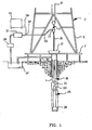
- Figure 1 depicts one example of drilling operations conducted in accordance with the present invention with an improved downhole drill bit which includes within it a memory device which records sensor data during drilling operations.
- a conventional rig 3 includes a derrick 5, derrick floor 7, draw works 9, hook 11, swivel 13, kelly joint 15, and rotary table 17.
- a drillstring 19 which includes drill pipe section 21 and drill collar section 23 extends downward from rig 3 into wellbore 1.
- Drill collar section 23 preferably includes a number of tubular drill collar members which connect together, including a measurement-while-drilling logging subassembly and cooperating mud pulse telemetry data transmission subassembly, which are collectively referred to hereinafter as "measurement and communication system 25".
- drilling fluid is circulated from mud pit 27 through mud pump 29, through a desurger 31, and through mud supply line 33 into swivel 13.
- the drilling mud flows through the kelly joint and an axial central bore in the drillstring.
- jets which are located in downhole drill bit 26 which is connected to the lowermost portion of measurement and communication system 25.
- the drilling mud flows back up through the annular space between the outer surface of the drillstring and the inner surface of wellbore 1, to be circulated to the surface where it is returned to mud pit 27 through mud return line 35.
- a shaker screen (which is not shown) separates formation cuttings from the drilling mud before it returns to mud pit 27.
- measurement and communication system 25 utilizes a mud pulse telemetry technique to communicate data from a downhole location to the surface while drilling operations take place.
- transducer 37 is provided in communication with mud supply line 33. This transducer generates electrical signals in response to drilling mud pressure variations. These electrical signals are transmitted by a surface conductor 39 to a surface electronic processing system 41, which is preferably a data processing system with a central processing unit for executing program instructions, and for responding to user commands entered through either a keyboard or a graphical pointing device.
- the mud pulse telemetry system is provided for communicating data to the surface concerning numerous downhole conditions sensed by well logging transducers or measurement systems that are ordinarily located within measurement and communication system 25.
- Mud pulses that define the data propagated to the surface are produced by equipment which is located within measurement and communication system 25.
- equipment typically comprises a pressure pulse generator operating under control of electronics contained in an instrument housing to allow drilling mud to vent through an orifice extending through the drill collar wall. Each time the pressure pulse generator causes such venting, a negative pressure pulse is transmitted to be received by surface transducer 37.
- Such a telemetry system is described and explained in U.S.Patent No. 4,216,536 to More.
- An alternative conventional arrangement generates and transmits positive pressure pulses.
- the circulating mud provides a source of energy for a turbine-driven generator subassembly which is located within measurement and communication system 25.
- the turbine-driven generator generates electrical power for the pressure pulse generator and for various circuits including those circuits which form the operational components of the measurement-while-drilling tools.
- batteries may be provided, particularly as a back-up for the turbine-driven generator.
- FIG. 2 is a perspective view of an improved downhole drill bit 26 in accordance with the present invention.
- the downhole drill bit includes an externally-threaded upper end 53 which is adapted for coupling with an internally-threaded box end of the lowermost portion of the drillstring. Additionally, it includes bit body 55.
- Nozzle 57 (and other obscured nozzles) jets fluid that is pumped downward through the drillstring to cool downhole drill bit 26, clean the cutting teeth of downhole drill bit 26, and transport the cuttings up the annulus.
- Improved downhole drill bit 26 includes three bit legs (but may alternatively include a lesser or greater number of legs) which extend downward from bit body 55, which terminate at journal bearings (not depicted in Figure 2 but depicted in Figure 3 , but which may alternatively include any other conventional bearing, such as a roller bearing) which receive rolling cone cutters 63, 65, 67.
- Each of rolling cone cutters 63, 65, 67 is lubricated by a lubrication system which is accessed through compensator caps 59, 60 (obscured in the view of Figure 2 ), and 61.
- Each of rolling cone cutters 63, 65, 67 include cutting elements, such as cutting elements 71, 73, and optionally include gage trimmer inserts, such as gage trimmer insert 75.
- cutting elements may comprise tungsten carbide inserts which are press fit into holes provided in the rolling cone cutters.
- the cutting elements may be machined from the steel which forms the body of rolling cone cutters 63, 65, 67.
- gage trimmer inserts such as gage trimmer insert 75, are press fit into holes provided in the rolling cone cutters 63, 65, 67. No particular type, construction, or placement of the cutting elements is required for the present invention, and the drill bit depicted in Figures 2 and 3 is merely illustrative of one widely available downhole drill bit.
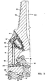
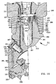
- Figure 3 is a one-quarter longitudinal section view of the improved downhole drill bit 26 of Figure 2 .
- One bit leg 81 is depicted in this view.
- Central bore 83 is defined interiorly of bit leg 81.
- Externally threaded pin 53 is utilized to secure downhole drill bit 26 to an adjoining drill collar member.
- any conventional or novel coupling may be utilized.
- a lubrication system 85 is depicted in the view of Figure 3 and includes compensator 87 which includes compensator diaphragm 89, lubrication passage 91, lubrication passage 93, and lubrication passage 95.
- Lubrication passages 91, 93, and 95 are utilized to direct lubricant from compensator 97 to an interface between rolling cone cutter 63 and cantilevered journal bearing 97, to lubricate the mechanical interface 99 thereof.
- Rolling cone cutter 63 is secured in position relative to cantilevered journal bearing 97 by ball lock 101 which is moved into position through lubrication passage 93 through an opening which is filled by plug weld 103.
- the interface 99 between cantilevered journal bearing 97 and rolling cone cutter 63 is sealed by o-ring seal 105; alternatively, a rigid or mechanical face seal may be provided in lieu of an o-ring seal.
- Lubricant which is routed from compensator 87 through lubrication passages 91, 93, and 95 lubricates interface 99 to facilitate the rotation of rolling cone cutter 63 relative to cantilevered journal bearing 97.
- Compensator 87 may be accessed from the exterior of downhole drill bit 26 through removable compensator cap 61.
- the plurality of operating condition sensors which are placed within downhole drill bit 26 are not depicted in the view of Figure 3 . The operating condition sensors are however shown in their positions in the views of Figures 8A through 8H .
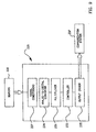
- FIG. 4 is a block diagram representation of the components which are utilized to perform signal processing, data analysis, and communication operations, in accordance with the present invention.
- sensors such as sensors 401, 403, provide analog signals to analog-to-digital converters 405, 407, respectively.
- the digitized sensor data is passed to data bus 409 for manipulation by controller 411.
- the data may be stored by controller 411 in nonvolatile memory 417.
- Program instructions which are executed by controller 411 may be maintained in ROM 419, and called for execution by controller 411 as needed.
- Controller 411 may comprise a conventional microprocessor which operates on eight or sixteen bit binary words.Controller 411 may be programmed to administer merely the recordation of sensor data in memory, in the most basic embodiment of the present invention; however, in more elaborate embodiments of the present invention, controller 411 may be utilized to perform analyses of the sensor data in order to detect impending failure of the downhole drill bit and/or to supervise communication of the processed or unprocessed sensor data to another location within the drillstring or wellbore. The preprogrammed analyses may be maintained in memory in ROM 419, and loaded onto controller 411 in a conventional manner, for execution during drilling operations.
- controller 411 may pass digital data and/or warning signals indicative of impending downhole drill bit failure to input/output devices 413, 415 for communication to either another location within the wellbore or drillstring, or to a surface location.
- the input/output devices 413, 415 may be also utilized for reading recorded sensor data from nonvolatile memory 417 at the termination of drilling operations for the particular downhole drill bit, in order to facilitate the analysis of the bit's drill performance during drilling operation.
- a wireline reception device may be lowered within the drillstring during drilling operations to receive data which is transmitted by input/output device 413, 415 in the form of electromagnetic transmissions.
- this data is to determine whether the purchaser of the downhole drill bit has operated the downhole drill bit in a responsible manner; that is, in a manner which is consistent with the manufacturer's instruction. This may help resolve conflicts and disputes relating to the performance or failure in performance of the downhole drill bit. It is beneficial for the manufacturer of the downhole drill bit to have evidence of product misuse as a factor which may indicate that the purchaser is responsible for financial loss instead of the manufacturer. Still other uses of the data include the utilization of the data to determine the efficiency and reliability of particular downhole drill bit designs. The manufacturer may utilize the data gathered at the completion of drilling operations of a particular downhole drill bit in order to determine the suitability of the downhole drill bit for that particular drilling operation.
- the downhole drill bit manufacturer may develop more sophisticated, durable, and reliable designs for downhole drill bits.
- the data may alternatively be utilized to provide a record of the operation of the bit, in order to supplement resistivity and other logs which are developed during drilling operations, in a conventional manner.
- the service companies which provide measurement-while-drilling operations are hard pressed to explain irregularities in the logging data.
- Having a complete record of the operating conditions of the downhole drill bit during the drilling operations in question may allow the provider of measurement-while-drilling services to explain irregularities in the log data.
- Many other conventional or novel uses may be made of the recorded data which either improve or enhance drilling operations, the control over drilling operations, or the manufacture, design and use of drilling tools. The most important of all possible uses is the use of the present invention to obtain the full utilization of bit life through either real-time monitoring, forensic use of recorded data, or a combination of both.
- Nonvolatile memory 417 includes a memory array 421. As is known in the art, memory array 421 is addressed by row decoder 423 and column decoder 425. Row decoder 423 selects a row of memory array 417 in response to a portion of an address received from the address bus 409. The remaining lines of the address bus 409 are connected to column decoder 425, and used to select a subset of columns from the memory array 417.
- Sense amplifiers 427 are connected to column decoder 425, and sense the data provided by the cells in memory array 421. The sense amps provide data read from the array 421 to an output (not shown), which can include latches as is well known in the art.
- Write driver 429 is provided to store data into selected locations within the memory array 421 in response to a write control signal.
- the cells in the array 421 of nonvolatile memory 417 can be any of a number of different types of cells known in the art to provide nonvolatile memory.
- EEPROM memories are well known in the art, and provide a reliable, erasable nonvolatile memory suitable for use in applications such as recording of data in wellbore environments.
- the cells of memory array 421 can be other designs known in the art, such as SRAM memory arrays utilized with battery back-up power sources.
- one or more operating condition sensors are carried by the production downhole drill bit, and are utilized to detect a particular operating condition.
- One possible technique for determining which particular sensors are included in the production downhole drill bits will now be described in detail.
- a plurality of operating condition sensors may be placed on at least one test downhole drill bit.
- a large number of test downhole drill bits are examined.
- the test downhole drill bits may then be subjected to at least one simulated drilling operation, and data may be recorded with respect to time with the plurality of operating condition sensors.
- the data may then be examined to identify impending downhole drill bit failure indicators.
- selected ones of the plurality of operating condition sensors may be selected for placement in production downhole drill bits.
- a monitoring system may be provided for comparing data obtained during drilling operations with particular ones of the impending downhole drill bit failure indicators.
- drilling operations are then conducted with the production downhole drill bit, and the monitoring system may be utilized to identify impending downhole drill bit failure.
- the data may be telemetered uphole during drilling operations to provide an indication of impending downhole drill bit failure utilizing any one of a number of known, prior art data communications systems.
- Bit leg 80 may be equipped with strains sensors 125 in order to measure axial strain, shear strain, and bending strain.
- Bit leg 81 may likewise be equipped with strain sensors 127 in order to measure axial strain, shear strain, and bending strain.
- Bit leg 82 may also equipped with strain sensors 129 for measuring axial strain, shear strain, and bending strain.
- Journal bearing 96 may be equipped with temperature sensors 131 in order to measure the temperature at the cone mouth, thrust face, and shirt tail of the cantilevered journal bearing 97; likewise, journal bearing 97 may be equipped with temperature sensors 133 for measuring the temperature at the cone mouth, thrust face, and shirt tail of the cantilevered journal bearing 97; journal bearing 98 may be equipped with temperature sensors 135 at the cone mouth, thrust face, and shirt tail of cantilevered journal bearing 98 in order to measure temperature at those locations.
- different types of bearings may be utilized, such as roller bearings. Temperature sensors would be appropriately located therein.
- Lubrication system may be equipped with reservoir pressure sensor 137 and pressure at seal sensor 139 which together are utilized to develop a measurement of the differential pressure across the seal of journal bearing 96.
- lubrication system 85 may be equipped with reservoir pressure sensor 141 and pressure at seal sensor 143 which develop a measurement of the pressure differential across the seal at journal bearing 97.
- lubrication system 86 which may be equipped with reservoir pressure sensor 145 and pressure at seal sensor 147 which develop a measurement of the pressure differential across the seal of journal bearing 98.
- acceleration sensors 149 may be provided on bit body 55 in order to measure the x-axis, y-axis, and z-axis components of acceleration experienced by bit body 55.
- ambient pressure sensor 151 and ambient temperature sensor 153 may be provided to monitor the ambient pressure and temperature of wellbore 1.
- Additional sensors may be provided in order to obtain and record data pertaining to the wellbore and surrounding formation, such as, for example and without limitation, sensors which provide an indication about one or more electrical or mechanical properties of the wellbore or surrounding formation.
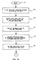
- the overall technique which may be used for establishing an improved downhole drill bit with a monitoring system is set forth in flowchart form in Figure 7 .
- the process begins at step 171, and continues in step 173 by the placement of operating condition sensors, such as those depicted in block diagram in Figure 6 , on a test bit or bits for which a monitoring system is desired.
- the test bits are then subjected to simulated drilling operations, in accordance with step 175, and data from the operating condition sensors is recorded. Utilizing the particular sensors depicted in block diagram in Figure 6 , information relating to the strain detected at bit legs 80, 81, and 82 will be recorded.
- journal bearings 96, 97, and 98 information relating to the temperature detected at journal bearings 96, 97, and 98 will also be recorded.Furthermore, information pertaining to the pressure within lubrication systems 84, 85, 86 will be recorded. Information pertaining to the acceleration of bit body 55 will be recorded. Finally, ambient temperature and pressure within the simulated wellbore will be recorded.
- the collected data may be examined to identify indicators for impending downhole drill bit failure.
- indicators for impending downhole drill bit failure include, but are not limited to, some of the following:
- the simulated drilling operations are preferably conducted using a test rig, which allows the operator to strictly control all of the pertinent factors relating to the drilling operation, such as weight on bit, torque, rotation rate, bending loads applied to the string, mud weights, temperature, pressure, and rate of penetration.
- the test bits are actuated under a variety of drilling and wellbore conditions and are operated until failure occurs.
- the recorded data can be utilized to establish thresholds which indicate impending bit failure during actual drilling operations. For a particular downhole drill bit type, the data is assessed to determine which particular sensor or sensors will provide the earliest and clearest indication of impending bit failure.
- Step 177 in Figure 7 corresponds to the step of identifying impending downhole drill bit failure indicators from the data amassed during simulated drilling operations.
- field testing may be conducted to supplement the data obtained during simulated drilling operations, and the particular operating condition sensors which are eventually placed in production downhole drill bits selected based upon a combination of the data obtained during simulated drilling operations and the data obtained during field testing.
- particular ones of the operating condition sensors are included in a particular type of production downhole drill bit.
- a monitoring system is included in the production downhole drill bit, and is defined or programmed to continuously compare sensor data with a pre-established threshold for each sensor.
- thresholds For example, and without limitation, the following types of thresholds can be established:
- the temperature thresholds set for journal bearings 96, 97, or 98, and the pressure thresholds established for lubrication systems 94, 95, 96 may be relative figures which are established with respect to ambient pressure and ambient temperature in the wellbore during drilling operations as detected by ambient pressure sensor 151 and temperature sensor 153 (both of Figure 6 ).
- Such thresholds may be established by providing program instructions to a controller which is resident within improved downhole drill bit 26, or by providing voltage and current thresholds for electronic circuits provided to continuously or intermittently compare data sensed in real time during drilling operations with pre-established thresholds for particular sensors which have been included in the production downhole drill bits.
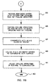
- the step of programming the monitoring system is identified in the flowchart of Figure 7 as step 183.
- step 185 drilling operations are performed and data is monitored to detect impending downhole drill bit failure by continuously comparing data measurements with pre-established and predefined thresholds (either minimum, maximum, or minimum and maximum thresholds).
- a data communication system such as a measurement-while-drilling telemetry system.
- step 189 the measurement-while-drilling telemetry system is utilized to communicate data to the surface. The drilling operator monitors this data and then adjusts drilling operations in response to such communication, in accordance with step 191.
- the potential alarm conditions may be hierarchically arranged in order of seriousness, in order to allow the drilling operator to intelligently respond to potential alarm conditions. For example, loss of pressure within lubrication systems 84, 85, or 86 may define the most severe alarm condition.
- a secondary condition may be an elevation in temperature at journal bearings 96, 97, 98.
- an elevation in strain in bit legs 80, 81, 82 may define the next most severe alarm condition.
- Bit body acceleration may define an alarm condition which is relatively unimportant in comparison to the others.
- different identifiable alarm conditions may be communicated to the surface to allow the operator to exercise independent judgement in determining how to adjust drilling operations.
- the alarm conditions may be combined to provide a composite alarm condition which is composed of the various available alarm conditions.
- an arabic number between 1 and 10 may be communicated to the surface with 1 identifying a relatively low level of alarm, and 10 identifying a relatively high level of alarm.
- the various alarm components which are summed to provide this single numerical indication of alarm conditions may be weighted in accordance with relative importance.
- a loss of pressure within lubrication systems 84, 85, or 86 may carry a weight two or three times that of other alarm conditions in order to weight the composite indicator in a manner which emphasizes those alarm conditions which are deemed to be more important than other alarm conditions.
- the types of responses available to the operator include an adjustment in the weight on bit, the torque, and the rotation rate applied to the drillstring.
- the operator may respond by including or excluding particular drilling additives to the drilling mud.
- the operator may respond by pulling the string and replacing the bit.
- a variety of other conventional operator options are available. After the operator performs the particular adjustments, the process ends in accordance with step 193.
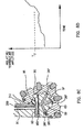
- Figures 8A through 8H depict sensor placement in the improved downhole drill bit 26 of the present invention with corresponding graphical presentations of exemplary thresholds which may be established with respect to each particular operating condition being monitored by the particular sensor.
- Figures 8A and 8B relate to the monitoring of pressure in lubrication systems of the improved downhole drill bit 26.
- pressure sensor 201 communicates with compensator 85 and provides an electrical signal through conductor 205 which provides an indication of the amplitude of the pressure within compensator 85.
- Conductor path 203 is provided through downhole drill bit 26 to allow the conductor to pass to the monitoring system carried by downhole drill bit 26. This measurement may be compared to ambient pressure to develop a measurement of the pressure differential across the seal.
- Figure 8B is a graphical representation of the diminishment of pressure amplitude with respect to time as the seal integrity of compensator 85 is impaired.
- the pressure threshold PT is established. Once the monitoring system determines that the pressure within compensator 85 falls below this pressure threshold, an alarm condition is determined to exist.
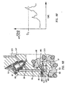
- FIG 8C depicts the placement of temperature sensors 207 relative to cantilevered journal bearing 97.
- Temperature sensors 207 are located at the cone mouth, shirt tail and thrust face of journal bearing 97, and communicate electrical signals via conductor 209 to the monitoring system to provide a measure of either the absolute or relative temperature amplitude. When relative temperature amplitude is provided, this temperature is computed with respect to the ambient temperature of the wellbore.
- Conductor path 211 is machined within downhole drill bit 26 to allow conductor 209 to pass to the monitoring system.
- Figure 8D graphically depicts the elevation of temperature amplitude with respect to time as the lubrication system for journal bearing 97 fails.
- a temperature threshold TT is established to define the alarm condition. Temperatures which rise above the temperature threshold triggers an alarm condition.
- Figure 8E depicts the location of strain sensors 213 relative to downhole drill bit 26.
- Strain sensors 213 communicate at least one signal which is indicative of at least one of axial strain, shear strain, and/or bending strain via conductors 215. These signals are provided to a monitoring system.
- Pathway 217 is defined within downhole drill bit 26 to allow for conductors 215 to pass to the monitoring system.
- Figure 8F is graphical representation of strain amplitude with respect to time for a particular one of axial strain, shear strain, and/or bending strain. As is shown, a strain threshold ST may be established. Strain which exceeds the strain threshold triggers an alarm condition.
- Figure 8G provides a representation of acceleration sensors 219 which provide an indication of the x-axis, y-axis, and/or z-axis acceleration of bit body 55.Conductors 221 pass through passage 223 to monitoring system 225.
- Figure 8H provides a graphical representation of the acceleration amplitude with respect to time.
- An acceleration threshold AT may be established to define an alarm condition. When a particular acceleration exceeds the amplitude threshold, an alarm condition is determined to exist.
- the improved downhole drill bit 26 of the present invention may further include a pressure sensor for detecting ambient wellbore pressure, and a temperature sensor for detecting ambient wellbore temperatures. Data from such sensors allows for the calculation of a relative pressure or temperature threshold.
- FIG. 9 is a block diagram depiction of monitoring system 225 which is optionally carried by improved downhole drill bit 26.
- Monitoring system 225 receives real-time data from sensors 226, and subjects the analog signals to signal conditioning such as filtering and amplification at signal conditioning block 227. Then, monitoring system 225 subjects the analog signal to an analog-to-digital conversion at analog-to-digital converter 229. The digital signal is then multiplexed at multiplexer 231 and routed as input to controller 233. The controller continuously compares the amplitudes of the data signals (and, alternatively, the rates of change) to pre-established thresholds which are recorded in memory.
- Controller 223 provides an output through output driver 235 which provides a signal to communication system 237.
- downhole drill bit 26 includes a communication system which is suited for communicating of either one or both of the raw data or one or more warning signals to a nearby subassembly in the drill collar.
- Communication system 237 would then be utilized to transmit either the raw data or warning signals a short distance through either electrical signals, electromagnetic signals, or acoustic signals.
- One available technique for communicating data signals to an adjoining subassembly in the drill collar is depicted, described, and claimed in U.S. Patent No. 5,129,471 which issued on July 14, 1992 to Howard, which is entitled "Wellbore Tool With Hall Effect Coupling".
- the monitoring system includes a predefined amount of memory which can be utilized for recording continuously or intermittently the operating condition sensor data.
- This data may be communicated directly to an adjoining tubular subassembly, or a composite failure indication signal may be communicated to an adjoining subassembly.
- substantially more data may be sampled and recorded than is communicated to the adjoining subassemblies for eventual communication to the surface through conventional mud pulse telemetry technology. It is useful to maintain this data in memory to allow review of the more detailed readings after the bit is retrieved from the wellbore.
- This information can be used by the operator to explain abnormal logs obtained during drilling operations.Additionally, it can be used to help the well operator select particular bits for future runs in the particular well.
- FIG. 10 is a perspective view of an earth-boring bit 511 of the fixed-cutter variety embodying the present invention.
- Bit 511 is threaded 513 at its upper extent for connection into a drillstring.
- a cutting end 515 at a generally opposite end of bit 511 is provided with a plurality of diamond or hard metal cutters 517, arranged about cutting end 515 to effect efficient disintegration of formation material as bit 511 is rotated in a borehole.
- a gage surface 519 extends upwardly from cutting end 515 and is proximal to and contacts the sidewall of the borehole during drilling operation of bit 511.
- a plurality of channels or grooves 521 extend from cutting end 515 through gage surface 519 to provide a clearance area for formation and removal of chips formed by cutters 517.
- gage inserts 523 are provided on gage surface 519 of bit 511. Active, shear cutting gage inserts 523 on gage surface 519 of bit 511 provide the ability to actively shear formation material at the sidewall of the borehole to provide improved gage-holding ability in earth-boring bits of the fixed cutter variety.
- Bit 511 is illustrated as a PDC ("polycrystalline diamond cutter") bit, but inserts 523 are equally useful in other fixed cutter or drag bits that include a gage surface for engagement with the sidewall of the borehole.
- FIG 11 is a fragmentary longitudinal section view of fixed-cutter downhole drill bit 511 of Figure 10 , with threads 513 and a portion of bit body 525 depicted.
- central bore 527 passes centrally through fixed-cutter downhole drill bit 511.
- monitoring system 529 is disposed in cavity 530.
- a conductor 531 extends downward through cavity 533 to accelerometers 535 which are provided to continuously measure the x-axis, y-axis, and/or z-axis components of acceleration of bit body 525.
- Accelerometers 535 provide a continuous measure of the acceleration, and monitoring system 529 continuously compares the acceleration to redefined acceleration thresholds which have been predetermined to indicate impending bit failure.
- Fixed cutter drill bits differ from rotary cone rock bits in that rather complicated steering and drive subassemblies (such as a Moincau principle mud motor) are commonly closely associated with fixed cutter drill bits, and are utilized to provide for more precise and efficient drilling, and are especially useful in a directional drilling operation.
- steering and drive subassemblies such as a Moincau principle mud motor
- a hardware communication system may be adequate for passing sensor data to a location within the drilling assembly for recordation in memory and optional processing operations.
Landscapes
- Engineering & Computer Science (AREA)
- Geology (AREA)
- Life Sciences & Earth Sciences (AREA)
- Mining & Mineral Resources (AREA)
- Physics & Mathematics (AREA)
- Environmental & Geological Engineering (AREA)
- Fluid Mechanics (AREA)
- General Life Sciences & Earth Sciences (AREA)
- Geochemistry & Mineralogy (AREA)
- Mechanical Engineering (AREA)
- Geophysics (AREA)
- Remote Sensing (AREA)
- Earth Drilling (AREA)
- Drilling And Boring (AREA)
Claims (15)
- Verfahren zum Überwachen wenigstens einer Betriebsbedingung eines Bohrmeißels während Bohroperationen, das Folgendes umfasst:das Anordnen mehrerer Betriebsbedingungssensoren (125-153) auf wenigstens einem Erprobungsbohrmeißel,das Unterwerfen des wenigstens einen Erprobungsbohrmeißels wenigstens einer simulierten Bohroperation,das Aufzeichnen von Daten mit den mehreren Betriebsbedingungssensoren (125-153), wobei in den Daten Indikatoren für bevorstehenden Bohrmeißel-Ausfall identifiziert werden,das Einschließen derjenigen, die unter den mehreren Betriebsbcdingungssensoren ausgewählt wurden, in einen Förderbohrmeißel,das Einschließen eines Überwachungssystems in den Förderbohrmeißel, zum Vergleichen von während Bohroperationen gewonnenen Daten mit bestimmten der Indikatoren für bevorstehenden Bohrmeißel-Ausfall,das Durchführen von Bohroperationen mit dem Förderbohrmeißel,das Benutzen des Überwachungssystems während der Bohroperationen, um einen bevorstehenden Bohrmeißel-Ausfall zu identifizieren, unddas Übertragen der Daten nach über Tage während der Bohroperationen, um eine Anzeige des bevorstehenden Bohrmeißel-Ausfalls bereitzustellen.
- Verfahren nach Anspruch 1, wobei das Überwachungssystem innerhalb des Förderbohrmeißels getragen wird.
- Verfahren nach Anspruch 1 oder Anspruch 2, das ferner Folgendes umfasst:das Benutzen des Überwachungssystems, um während Bohroperationen Daten von den ausgewählten der mehreren Betriebsbedingungssensoren auFzuzeichnen.
- Verfahren nach Anspruch 3, das ferner Folgendes umfasst:das Zurückholen des Überwachungssystems mit dem Förderbohrmeißel unddas Untersuchen der in dem Überwachungssystem aufgezeichneten Daten.
- Verfahren nach einem der vorhergehenden Ansprüche, wobei die mehreren Betriebsbedingungssensoren wenigstens einen der folgenden Betriebsbedingungssensoren umfassen:Beanspruchungssensoren (125-129), die in wenigstens einem Meißelschenkel (81-83) des wenigstens einen Erprobungsbohrmeißels oder des Förderbohrmeißels angeordnet sind, um wenigstens einen der Parameter Axialbeanspruchung, Scherbeanspruchung und Biegebeanspruchung abzufühlen,Temperatursensoren (131-135), die in wenigstens einem Lager (96-98) des wenigstens einen Erprobungsbohrmeißels oder des Förderbohrmeißels angeordnet sind, um wenigstens einen der Parameter Temperatur an einer Kegelmündung des Lagers, Temperatur an einer Druckfläche des Lagers und Temperatur an einem Randanhang des Lagers zu messen,Schmiersystemsensoren (137-147), die in wenigstens einem Schmiersystem (84-86) des wenigstens einen Erprobungsbohrmeißels oder des Färderbohrmeißels angeordnet sind, um wenigstens einen der Parameter Behälterdruck und Dichtungsdruck zu messen,wenigstens einen Beschleunigungsmesser (149), um eine Beschleunigung eines Meißelkörpers (55) des wenigstens einen Erprobungsbohrmeißels oder des Förderbohrmeißels zu messen, undeinen Bohrlochsensor (151-153) zum Überwachen wenigstens eines der Parameter Umgebungsdruck in dem Bohrloch und Umgebungstemperatur in dem Bohrloch.
- Verfahren nach einem der vorhergehenden Ansprüche, wobei das Überwachungssystem Folgendes einschließt:ein programmierbares Steuergerät, das Programmanweisungen einschließt und das ein Warnsignal auslöst, falls während der Überwachungsoperationen wenigstens ein vordefiniertes Kriterium für bevorstehenden Ausfall erfüllt ist.
- Verfahren nach einem der vorhergehenden Ansprüche, wobei der Schritt des Übertragens von Daten Folgendes einschließt:das Übermitteln von Daten von dem Förderbohrmeißel zu einer Empfangsvorrichtung, die in einer röhrenförmigen Unterbaugruppe nahe dem Förderbohrmeißel angeordnet ist.
- Verfahren nach Anspruch 7, wobei der Schritt des Übertragens von Daten Folgendes einschließt:das Übermitteln von Daten von dem Förderbohrmeißel zu einer Empfangsvorrichtung, die in einer röhrenförmigen Unterbaugruppe nahe dem Förderbohrmeißel angeordnet ist,das Bereitstellen eines Spülungsimpuls-Übertragungskommunikationssystems zur Bohrverlaufsmessung unddas Benutzen des Spülungsimpuls-Übertragungssystems zur Bohrverlaufsmessung, um eine Anzeige des bevorstehenden Bohrmeißel-Ausfalls an die Oberflächenausrüstung zu übermitteln.
- Verfahren nach einem der vorhergehenden Ansprüche, das ferner Folgendes umfasst:das Unterwerfen des wenigstens einen Erprobungsbohrmeißels wenigstens einer Felderprobungsbohroperation,das Aufzeichnen von Daten mit den mehreren Betriebsbedingungssensoren während sowohl der wenigstens einen simulierten Bohroperation als auch der wenigstens einen Felderprobungsbohroperation unddas Identifizieren der Indikatoren für bevorstehenden Bohrmeißel-Ausfall in den während der wenigstens einen simulierten Bohroperation und der wenigstens einen Felderprobungsbohroperation gesammelten Daten.
- Verfahren nach einem der vorhergehenden Ansprüche, das ferner das Einstellen wenigstens eines Aspekts der Bohroperation als Reaktion auf die Handlung des Übertragens von Daten nach über Tage umfasst.
- Verfahren nach Anspruch 10, wobei das Einstellen wenigstens eines Aspekts der Bohroperation das Einstellen wenigstens einer Funktion umfasst, die ausgewählt ist aus einer Gruppe, die aus dem Einstellen eines Bohrmeißelauflast-Parameters, dem Einstellen eines Drehmoments an einem an dem Bohrmeißel befestigten Bohrstrang, dem Einstellen einer Drehgeschwindigkeit eines an dem Bohrmeißel befestigten Bohrstrangs, dem Einschließen eines Bohrzuschlagstoffs zu einer Spülung und dem Ausschließen eines Bohrzuschlagstoffs aus einer Spülung besteht.
- Verfahren nach einem der vorhergehenden Ansprüche, das ferner Folgendes umfasst:das Anordnen einer Prozessoreinrichtung in dem Förderbohrmeißel unddas Benutzen der Prozessoreinrichtung zum Durchführen wenigstens einer vordefinierten Analyse der während der Bohroperationen gewonnenen Daten während der Handlung des Ausführens von Bohroperationen.
- Verfahren nach Anspruch 12, wobei das Benutzen der Prozessoreinrichtung ferner das Identifizieren des bevorstehenden Bohrmeißel-Ausfalls vor einem Auftreten eines Meißelausfalls umfasst.
- Verfahren nach einem der vorhergehenden Ansprüche, das ferner Folgendes umfasst:das Zurückholen des Förderbohrmeißels nach der Handlung des Ausführens von Bohroperationen unddas Überprüfen der während der Bohsoperationen gewonnenen Daten.
- Verfahren nach Anspruch 14, das ferner das Feststellen, ob der Förderbohrmeißel auf eine angemessene Weise benutzt worden ist oder nicht, aus den während der Bohroperationen gewonnenen Daten umfasst.
Applications Claiming Priority (2)
| Application Number | Priority Date | Filing Date | Title |
|---|---|---|---|
| US39032295A | 1995-02-16 | 1995-02-16 | |
| EP96300934A EP0728915B1 (de) | 1995-02-16 | 1996-02-12 | Verfahren und Vorrichtung zum Erfassen und Aufzeichnen der Einsatzbedingungen eines Bohrmeissels während des Bohrens |
Related Parent Applications (2)
| Application Number | Title | Priority Date | Filing Date |
|---|---|---|---|
| EP96300934A Division EP0728915B1 (de) | 1995-02-16 | 1996-02-12 | Verfahren und Vorrichtung zum Erfassen und Aufzeichnen der Einsatzbedingungen eines Bohrmeissels während des Bohrens |
| EP96300934.5 Division | 1996-02-12 |
Publications (3)
| Publication Number | Publication Date |
|---|---|
| EP1632643A2 EP1632643A2 (de) | 2006-03-08 |
| EP1632643A3 EP1632643A3 (de) | 2007-07-25 |
| EP1632643B1 true EP1632643B1 (de) | 2011-06-01 |
Family
ID=23542030
Family Applications (3)
| Application Number | Title | Priority Date | Filing Date |
|---|---|---|---|
| EP05077687A Expired - Lifetime EP1632643B1 (de) | 1995-02-16 | 1996-02-12 | Verfahren und Vorrichtung zum Erfassen und Aufzeichnen der Einsatzbedingungen eines Bohrmeissels während des Bohrens |
| EP96300934A Expired - Lifetime EP0728915B1 (de) | 1995-02-16 | 1996-02-12 | Verfahren und Vorrichtung zum Erfassen und Aufzeichnen der Einsatzbedingungen eines Bohrmeissels während des Bohrens |
| EP05077688A Expired - Lifetime EP1632644B1 (de) | 1995-02-16 | 1996-02-12 | Verfahren und Vorrichtung zum Erfassen und Aufzeichnen der Einsatzbedingungen eines Bohrmeissels während des Bohrens |
Family Applications After (2)
| Application Number | Title | Priority Date | Filing Date |
|---|---|---|---|
| EP96300934A Expired - Lifetime EP0728915B1 (de) | 1995-02-16 | 1996-02-12 | Verfahren und Vorrichtung zum Erfassen und Aufzeichnen der Einsatzbedingungen eines Bohrmeissels während des Bohrens |
| EP05077688A Expired - Lifetime EP1632644B1 (de) | 1995-02-16 | 1996-02-12 | Verfahren und Vorrichtung zum Erfassen und Aufzeichnen der Einsatzbedingungen eines Bohrmeissels während des Bohrens |
Country Status (3)
| Country | Link |
|---|---|
| US (1) | US5813480A (de) |
| EP (3) | EP1632643B1 (de) |
| DE (1) | DE69635694T2 (de) |
Families Citing this family (147)
| Publication number | Priority date | Publication date | Assignee | Title |
|---|---|---|---|---|
| US6571886B1 (en) * | 1995-02-16 | 2003-06-03 | Baker Hughes Incorporated | Method and apparatus for monitoring and recording of the operating condition of a downhole drill bit during drilling operations |
| US6230822B1 (en) * | 1995-02-16 | 2001-05-15 | Baker Hughes Incorporated | Method and apparatus for monitoring and recording of the operating condition of a downhole drill bit during drilling operations |
| US5988243A (en) * | 1997-07-24 | 1999-11-23 | Black & Decker Inc. | Portable work bench |
| US7334652B2 (en) * | 1998-08-31 | 2008-02-26 | Halliburton Energy Services, Inc. | Roller cone drill bits with enhanced cutting elements and cutting structures |
| US20040140130A1 (en) * | 1998-08-31 | 2004-07-22 | Halliburton Energy Services, Inc., A Delaware Corporation | Roller-cone bits, systems, drilling methods, and design methods with optimization of tooth orientation |
| US20040236553A1 (en) * | 1998-08-31 | 2004-11-25 | Shilin Chen | Three-dimensional tooth orientation for roller cone bits |
| US20040230413A1 (en) * | 1998-08-31 | 2004-11-18 | Shilin Chen | Roller cone bit design using multi-objective optimization |
| US20040045742A1 (en) * | 2001-04-10 | 2004-03-11 | Halliburton Energy Services, Inc. | Force-balanced roller-cone bits, systems, drilling methods, and design methods |
| US20030051917A1 (en) * | 1998-08-31 | 2003-03-20 | Halliburton Energy Services, Inc. | Roller cone bits, methods, and systems with anti-tracking variation in tooth orientation |
| EP1112433B1 (de) * | 1998-08-31 | 2004-01-14 | Halliburton Energy Services, Inc. | Rollenbohrmeissel, zugehöriges Entwurfsverfahren und Drehbohrsystem |
| US6269892B1 (en) * | 1998-12-21 | 2001-08-07 | Dresser Industries, Inc. | Steerable drilling system and method |
| US7659722B2 (en) | 1999-01-28 | 2010-02-09 | Halliburton Energy Services, Inc. | Method for azimuthal resistivity measurement and bed boundary detection |
| US6163155A (en) * | 1999-01-28 | 2000-12-19 | Dresser Industries, Inc. | Electromagnetic wave resistivity tool having a tilted antenna for determining the horizontal and vertical resistivities and relative dip angle in anisotropic earth formations |
| US6321596B1 (en) | 1999-04-21 | 2001-11-27 | Ctes L.C. | System and method for measuring and controlling rotation of coiled tubing |
| US6308787B1 (en) | 1999-09-24 | 2001-10-30 | Vermeer Manufacturing Company | Real-time control system and method for controlling an underground boring machine |
| JP2001117909A (ja) * | 1999-10-21 | 2001-04-27 | Oki Electric Ind Co Ltd | マトリクス形式データの転置回路 |
| US6484819B1 (en) * | 1999-11-17 | 2002-11-26 | William H. Harrison | Directional borehole drilling system and method |
| US6516897B2 (en) * | 2000-02-25 | 2003-02-11 | Michael C. Thompson | Self-contained excavator and anchor apparatus and method |
| US6374930B1 (en) | 2000-06-08 | 2002-04-23 | Smith International, Inc. | Cutting structure for roller cone drill bits |
| US6637527B1 (en) | 2000-06-08 | 2003-10-28 | Smith International, Inc. | Cutting structure for roller cone drill bits |
| US6601660B1 (en) | 2000-06-08 | 2003-08-05 | Smith International, Inc. | Cutting structure for roller cone drill bits |
| US6612384B1 (en) | 2000-06-08 | 2003-09-02 | Smith International, Inc. | Cutting structure for roller cone drill bits |
| US6604587B1 (en) | 2000-06-14 | 2003-08-12 | Smith International, Inc. | Flat profile cutting structure for roller cone drill bits |
| US6530441B1 (en) | 2000-06-27 | 2003-03-11 | Smith International, Inc. | Cutting element geometry for roller cone drill bit |
| US6443242B1 (en) | 2000-09-29 | 2002-09-03 | Ctes, L.C. | Method for wellbore operations using calculated wellbore parameters in real time |
| US6672409B1 (en) | 2000-10-24 | 2004-01-06 | The Charles Machine Works, Inc. | Downhole generator for horizontal directional drilling |
| GB2382611B (en) * | 2000-10-27 | 2004-04-14 | Baker Hughes Inc | Method and apparatus for monitoring and recording of the operating condition of a downhole drill bit during drilling operations |
| US6681633B2 (en) | 2000-11-07 | 2004-01-27 | Halliburton Energy Services, Inc. | Spectral power ratio method and system for detecting drill bit failure and signaling surface operator |
| US6817425B2 (en) | 2000-11-07 | 2004-11-16 | Halliburton Energy Serv Inc | Mean strain ratio analysis method and system for detecting drill bit failure and signaling surface operator |
| US6648082B2 (en) * | 2000-11-07 | 2003-11-18 | Halliburton Energy Services, Inc. | Differential sensor measurement method and apparatus to detect a drill bit failure and signal surface operator |
| US7357197B2 (en) | 2000-11-07 | 2008-04-15 | Halliburton Energy Services, Inc. | Method and apparatus for monitoring the condition of a downhole drill bit, and communicating the condition to the surface |
| US6722450B2 (en) * | 2000-11-07 | 2004-04-20 | Halliburton Energy Svcs. Inc. | Adaptive filter prediction method and system for detecting drill bit failure and signaling surface operator |
| US6712160B1 (en) | 2000-11-07 | 2004-03-30 | Halliburton Energy Services Inc. | Leadless sub assembly for downhole detection system |
| US6619411B2 (en) * | 2001-01-31 | 2003-09-16 | Smith International, Inc. | Design of wear compensated roller cone drill bits |
| DE10116363B4 (de) * | 2001-04-02 | 2006-03-16 | Tracto-Technik Gmbh | Bohrkopf einer Bohreinrichtung, insbesondere Spülbohrkopf einer Flachbohreinrichtung |
| US6850068B2 (en) * | 2001-04-18 | 2005-02-01 | Baker Hughes Incorporated | Formation resistivity measurement sensor contained onboard a drill bit (resistivity in bit) |
| US6467341B1 (en) | 2001-04-24 | 2002-10-22 | Schlumberger Technology Corporation | Accelerometer caliper while drilling |
| US6698536B2 (en) | 2001-10-01 | 2004-03-02 | Smith International, Inc. | Roller cone drill bit having lubrication contamination detector and lubrication positive pressure maintenance system |
| US6739413B2 (en) | 2002-01-15 | 2004-05-25 | The Charles Machine Works, Inc. | Using a rotating inner member to drive a tool in a hollow outer member |
| US7347283B1 (en) | 2002-01-15 | 2008-03-25 | The Charles Machine Works, Inc. | Using a rotating inner member to drive a tool in a hollow outer member |
| US20030200127A1 (en) * | 2002-04-18 | 2003-10-23 | Mcqueen Talmadge Keith | Job site problem solution systems with internet interface |
| US6814162B2 (en) * | 2002-08-09 | 2004-11-09 | Smith International, Inc. | One cone bit with interchangeable cutting structures, a box-end connection, and integral sensory devices |
| DE10254942B3 (de) * | 2002-11-25 | 2004-08-12 | Siemens Ag | Verfahren zur automatischen Ermittlung der Koordinaten von Abbildern von Marken in einem Volumendatensatz und medizinische Vorrichtung |
| US7026950B2 (en) * | 2003-03-12 | 2006-04-11 | Varco I/P, Inc. | Motor pulse controller |
| US7434632B2 (en) * | 2004-03-02 | 2008-10-14 | Halliburton Energy Services, Inc. | Roller cone drill bits with enhanced drilling stability and extended life of associated bearings and seals |
| US7555391B2 (en) * | 2004-03-04 | 2009-06-30 | Halliburton Energy Services, Inc. | Multiple distributed force measurements |
| US7168506B2 (en) * | 2004-04-14 | 2007-01-30 | Reedhycalog, L.P. | On-bit, analog multiplexer for transmission of multi-channel drilling information |
| US7946356B2 (en) * | 2004-04-15 | 2011-05-24 | National Oilwell Varco L.P. | Systems and methods for monitored drilling |
| US20050257961A1 (en) * | 2004-05-18 | 2005-11-24 | Adrian Snell | Equipment Housing for Downhole Measurements |
| DK1598520T3 (da) * | 2004-05-19 | 2009-06-15 | Schlumberger Technology Bv | Registreringssystem til et borehul |
| US20050274545A1 (en) * | 2004-06-09 | 2005-12-15 | Smith International, Inc. | Pressure Relief nozzle |
| GB2460560B (en) | 2004-08-16 | 2010-01-13 | Halliburton Energy Serv Inc | Roller cone drill bits with optimized bearing structures |
| US20060065395A1 (en) * | 2004-09-28 | 2006-03-30 | Adrian Snell | Removable Equipment Housing for Downhole Measurements |
| US20060195265A1 (en) * | 2005-02-17 | 2006-08-31 | Reedhycalog Lp | Method of measuring stick slip, and system for performing same |
| US7604072B2 (en) * | 2005-06-07 | 2009-10-20 | Baker Hughes Incorporated | Method and apparatus for collecting drill bit performance data |
| US8376065B2 (en) * | 2005-06-07 | 2013-02-19 | Baker Hughes Incorporated | Monitoring drilling performance in a sub-based unit |
| US8100196B2 (en) * | 2005-06-07 | 2012-01-24 | Baker Hughes Incorporated | Method and apparatus for collecting drill bit performance data |
| US7849934B2 (en) * | 2005-06-07 | 2010-12-14 | Baker Hughes Incorporated | Method and apparatus for collecting drill bit performance data |
| DE112006002137T5 (de) | 2005-08-08 | 2008-06-26 | Halliburton Energy Services, Inc., Houston | Verfahren und Systeme zum Konstruieren und/oder Auswählen von Bohrausrüstung mit einer gewünschten Bohrmeißellenkbarkeit |
| US7860696B2 (en) | 2005-08-08 | 2010-12-28 | Halliburton Energy Services, Inc. | Methods and systems to predict rotary drill bit walk and to design rotary drill bits and other downhole tools |
| US7860693B2 (en) | 2005-08-08 | 2010-12-28 | Halliburton Energy Services, Inc. | Methods and systems for designing and/or selecting drilling equipment using predictions of rotary drill bit walk |
| US7444861B2 (en) * | 2005-11-22 | 2008-11-04 | Halliburton Energy Services, Inc. | Real time management system for slickline/wireline |
| US7554329B2 (en) * | 2006-04-07 | 2009-06-30 | Baker Hughes Incorporated | Method and apparatus for determining formation resistivity ahead of the bit and azimuthal at the bit |
| WO2007123877A2 (en) * | 2006-04-17 | 2007-11-01 | Baker Hughes Incorporated | Rotary drill bits, methods of inspecting rotary drill bits, apparatuses and systems therefor |
| US7284428B1 (en) * | 2006-06-23 | 2007-10-23 | Innovative Measurement Methods, Inc. | Sensor housing for use in a storage vessel |
| CA2655200C (en) | 2006-07-11 | 2013-12-03 | Halliburton Energy Services, Inc. | Modular geosteering tool assembly |
| WO2008021868A2 (en) | 2006-08-08 | 2008-02-21 | Halliburton Energy Services, Inc. | Resistivty logging with reduced dip artifacts |
| US8122954B2 (en) * | 2006-09-20 | 2012-02-28 | Baker Hughes Incorporated | Downhole depth computation methods and related system |
| US8899322B2 (en) * | 2006-09-20 | 2014-12-02 | Baker Hughes Incorporated | Autonomous downhole control methods and devices |
| US8528637B2 (en) | 2006-09-20 | 2013-09-10 | Baker Hughes Incorporated | Downhole depth computation methods and related system |
| US8274289B2 (en) | 2006-12-15 | 2012-09-25 | Halliburton Energy Services, Inc. | Antenna coupling component measurement tool having rotating antenna configuration |
| WO2008085946A2 (en) * | 2007-01-08 | 2008-07-17 | Baker Hughes Incorporated | Drilling components and systems to dynamically control drilling dysfunctions and methods of drilling a well with same |
| AU2007349251B2 (en) | 2007-03-16 | 2011-02-24 | Halliburton Energy Services, Inc. | Robust inversion systems and methods for azimuthally sensitive resistivity logging tools |
| US20090084606A1 (en) * | 2007-10-01 | 2009-04-02 | Doster Michael L | Drill bits and tools for subterranean drilling |
| US8245792B2 (en) * | 2008-08-26 | 2012-08-21 | Baker Hughes Incorporated | Drill bit with weight and torque sensors and method of making a drill bit |
| US20100078216A1 (en) * | 2008-09-25 | 2010-04-01 | Baker Hughes Incorporated | Downhole vibration monitoring for reaming tools |
| US8210280B2 (en) * | 2008-10-13 | 2012-07-03 | Baker Hughes Incorporated | Bit based formation evaluation using a gamma ray sensor |
| WO2010074678A2 (en) | 2008-12-16 | 2010-07-01 | Halliburton Energy Services, Inc. | Azimuthal at-bit resistivity and geosteering methods and systems |
| US8028764B2 (en) * | 2009-02-24 | 2011-10-04 | Baker Hughes Incorporated | Methods and apparatuses for estimating drill bit condition |
| US8170800B2 (en) | 2009-03-16 | 2012-05-01 | Verdande Technology As | Method and system for monitoring a drilling operation |
| US8245793B2 (en) * | 2009-06-19 | 2012-08-21 | Baker Hughes Incorporated | Apparatus and method for determining corrected weight-on-bit |
| US8397562B2 (en) * | 2009-07-30 | 2013-03-19 | Aps Technology, Inc. | Apparatus for measuring bending on a drill bit operating in a well |
| GB2473640A (en) * | 2009-09-21 | 2011-03-23 | Vetco Gray Controls Ltd | Condition monitoring of an underwater facility |
| US20110203805A1 (en) * | 2010-02-23 | 2011-08-25 | Baker Hughes Incorporated | Valving Device and Method of Valving |
| US8397800B2 (en) | 2010-12-17 | 2013-03-19 | Halliburton Energy Services, Inc. | Perforating string with longitudinal shock de-coupler |
| US8397814B2 (en) | 2010-12-17 | 2013-03-19 | Halliburton Energy Serivces, Inc. | Perforating string with bending shock de-coupler |
| US8985200B2 (en) | 2010-12-17 | 2015-03-24 | Halliburton Energy Services, Inc. | Sensing shock during well perforating |
| US8393393B2 (en) | 2010-12-17 | 2013-03-12 | Halliburton Energy Services, Inc. | Coupler compliance tuning for mitigating shock produced by well perforating |
| WO2012148429A1 (en) | 2011-04-29 | 2012-11-01 | Halliburton Energy Services, Inc. | Shock load mitigation in a downhole perforation tool assembly |
| US20120241169A1 (en) | 2011-03-22 | 2012-09-27 | Halliburton Energy Services, Inc. | Well tool assemblies with quick connectors and shock mitigating capabilities |
| US9080399B2 (en) | 2011-06-14 | 2015-07-14 | Baker Hughes Incorporated | Earth-boring tools including retractable pads, cartridges including retractable pads for such tools, and related methods |
| US9222350B2 (en) | 2011-06-21 | 2015-12-29 | Diamond Innovations, Inc. | Cutter tool insert having sensing device |
| US8960281B2 (en) | 2011-07-07 | 2015-02-24 | National Oilwell DHT, L.P. | Flowbore mounted sensor package |
| US9091152B2 (en) | 2011-08-31 | 2015-07-28 | Halliburton Energy Services, Inc. | Perforating gun with internal shock mitigation |
| WO2014003699A2 (en) | 2012-04-03 | 2014-01-03 | Halliburton Energy Services, Inc. | Shock attenuator for gun system |
| US20130297231A1 (en) * | 2012-05-04 | 2013-11-07 | Baker Hughes Incorporated | Automated Method of Ultrasonically Scanning Cutters While on the Bit for Crack Detection |
| US9267346B2 (en) * | 2012-07-02 | 2016-02-23 | Robertson Intellectual Properties, LLC | Systems and methods for monitoring a wellbore and actuating a downhole device |
| EP2855839A4 (de) * | 2012-07-23 | 2016-05-11 | Halliburton Energy Services Inc | Bohrverfahren mit audio- und videoeingängen zur ereigniserkennung |
| US8978749B2 (en) | 2012-09-19 | 2015-03-17 | Halliburton Energy Services, Inc. | Perforation gun string energy propagation management with tuned mass damper |
| US9598940B2 (en) | 2012-09-19 | 2017-03-21 | Halliburton Energy Services, Inc. | Perforation gun string energy propagation management system and methods |
| WO2014084866A1 (en) | 2012-12-01 | 2014-06-05 | Halliburton Energy Services, Inc. | Protection of electronic devices used with perforating guns |
| EP3071789B1 (de) | 2013-11-19 | 2020-02-26 | MinEx CRC Ltd | Bohrlochmessverfahren und -vorrichtung |
| US9927310B2 (en) | 2014-02-03 | 2018-03-27 | Aps Technology, Inc. | Strain sensor assembly |
| GB2537565A (en) | 2014-02-03 | 2016-10-19 | Aps Tech Inc | System, apparatus and method for guiding a drill bit based on forces applied to a drill bit |
| DE102014105014A1 (de) * | 2014-04-08 | 2015-10-08 | Montanuniversität Leoben | Hochpräzise Sensorik zum Ermitteln einer mechanischen Belastung eines Abbauwerkzeugs einer Tunnelbohrmaschine |
| US10113363B2 (en) | 2014-11-07 | 2018-10-30 | Aps Technology, Inc. | System and related methods for control of a directional drilling operation |
| WO2016099564A1 (en) * | 2014-12-19 | 2016-06-23 | Halliburton Energy Services, Inc. | Roller cone drill bit with embedded gamma ray detector |
| US9732791B1 (en) * | 2015-02-25 | 2017-08-15 | Us Synthetic Corporation | Bearing assemblies including tilting bearing elements and superhard sliding bearing elements, bearing assemblies including a substantially continuous bearing element and superhard sliding bearing elements, and related bearing apparatuses and methods |
| US10233700B2 (en) | 2015-03-31 | 2019-03-19 | Aps Technology, Inc. | Downhole drilling motor with an adjustment assembly |
| JP6170088B2 (ja) * | 2015-04-06 | 2017-07-26 | 中日本高速技術マーケティング株式会社 | Pcグラウトの充填調査及び再注入用孔削孔時のシース管検知方法、並びにpcグラウトの充填調査及び再注入用孔の削孔方法 |
| GB2550867B (en) * | 2016-05-26 | 2019-04-03 | Metrol Tech Ltd | Apparatuses and methods for sensing temperature along a wellbore using temperature sensor modules connected by a matrix |
| DE102016014685A1 (de) | 2016-12-12 | 2018-06-14 | Tracto-Technik Gmbh & Co. Kg | Verfahren und System zum Ermitteln einer Bodenklasse sowie Verwendung beim Ermitteln einer Bodenklasse |
| GB2581550B (en) * | 2017-05-15 | 2022-01-05 | Landmark Graphics Corp | Method and system to drill a wellbore and identify drill bit failure by deconvoluting sensor data |
| US10738587B2 (en) | 2018-05-04 | 2020-08-11 | Saudi Arabian Oil Company | Monitoring operating conditions of a rotary steerable system |
| US11111732B2 (en) | 2019-07-29 | 2021-09-07 | Saudi Arabian Oil Company | Drill bits with incorporated sensing systems |
| US11008816B2 (en) | 2019-07-29 | 2021-05-18 | Saudi Arabian Oil Company | Drill bits for oil and gas applications |
| US11414963B2 (en) | 2020-03-25 | 2022-08-16 | Saudi Arabian Oil Company | Wellbore fluid level monitoring system |
| US11125075B1 (en) | 2020-03-25 | 2021-09-21 | Saudi Arabian Oil Company | Wellbore fluid level monitoring system |
| US11280178B2 (en) | 2020-03-25 | 2022-03-22 | Saudi Arabian Oil Company | Wellbore fluid level monitoring system |
| CN111472749B (zh) * | 2020-04-20 | 2022-10-21 | 山西潞安矿业集团慈林山煤业有限公司李村煤矿 | 一种随钻温度监测及高温自动闭锁系统与方法 |
| CN111535762B (zh) * | 2020-05-20 | 2022-04-26 | 河南理工大学 | 一种钻头降温防尘器 |
| US11414984B2 (en) | 2020-05-28 | 2022-08-16 | Saudi Arabian Oil Company | Measuring wellbore cross-sections using downhole caliper tools |
| US11414985B2 (en) | 2020-05-28 | 2022-08-16 | Saudi Arabian Oil Company | Measuring wellbore cross-sections using downhole caliper tools |
| US11631884B2 (en) | 2020-06-02 | 2023-04-18 | Saudi Arabian Oil Company | Electrolyte structure for a high-temperature, high-pressure lithium battery |
| US11149510B1 (en) | 2020-06-03 | 2021-10-19 | Saudi Arabian Oil Company | Freeing a stuck pipe from a wellbore |
| US11391104B2 (en) | 2020-06-03 | 2022-07-19 | Saudi Arabian Oil Company | Freeing a stuck pipe from a wellbore |
| US11719089B2 (en) | 2020-07-15 | 2023-08-08 | Saudi Arabian Oil Company | Analysis of drilling slurry solids by image processing |
| US11255130B2 (en) | 2020-07-22 | 2022-02-22 | Saudi Arabian Oil Company | Sensing drill bit wear under downhole conditions |
| US11506044B2 (en) | 2020-07-23 | 2022-11-22 | Saudi Arabian Oil Company | Automatic analysis of drill string dynamics |
| US11867008B2 (en) | 2020-11-05 | 2024-01-09 | Saudi Arabian Oil Company | System and methods for the measurement of drilling mud flow in real-time |
| EP4015766B1 (de) * | 2020-12-21 | 2023-07-12 | BAUER Spezialtiefbau GmbH | Tiefbauwerkzeug und tiefbauverfahren |
| US11434714B2 (en) | 2021-01-04 | 2022-09-06 | Saudi Arabian Oil Company | Adjustable seal for sealing a fluid flow at a wellhead |
| US11697991B2 (en) | 2021-01-13 | 2023-07-11 | Saudi Arabian Oil Company | Rig sensor testing and calibration |
| US11668185B2 (en) | 2021-02-19 | 2023-06-06 | Saudi Arabian Oil Company | In-cutter sensor LWD tool and method |
| US11572752B2 (en) | 2021-02-24 | 2023-02-07 | Saudi Arabian Oil Company | Downhole cable deployment |
| US11727555B2 (en) | 2021-02-25 | 2023-08-15 | Saudi Arabian Oil Company | Rig power system efficiency optimization through image processing |
| US11566988B2 (en) | 2021-02-26 | 2023-01-31 | Saudi Arabian Oil Company | In-situ property evaluation of cutting element using acoustic emission technology during wear test |
| US11680883B2 (en) | 2021-02-26 | 2023-06-20 | Saudi Arabian Oil Company | Sensors to evaluate the in-situ property of cutting element during wear test |
| US11486202B2 (en) | 2021-02-26 | 2022-11-01 | Saudi Arabian Oil Company | Real-time polycrystalline diamond compact (PDC) bit condition evaluation using acoustic emission technology during downhole drilling |
| US11846151B2 (en) | 2021-03-09 | 2023-12-19 | Saudi Arabian Oil Company | Repairing a cased wellbore |
| US11414980B1 (en) | 2021-03-22 | 2022-08-16 | Saudi Arabian Oil Company | Charging and communication interface for drill bit nozzle-based sensing system |
| US11346207B1 (en) | 2021-03-22 | 2022-05-31 | Saudi Arabian Oil Company | Drilling bit nozzle-based sensing system |
| CN113605876B (zh) * | 2021-08-11 | 2023-07-18 | 沧州格锐特钻头有限公司 | 一种牙轮钻头状态检测方法 |
| US11624265B1 (en) | 2021-11-12 | 2023-04-11 | Saudi Arabian Oil Company | Cutting pipes in wellbores using downhole autonomous jet cutting tools |
| US11867012B2 (en) | 2021-12-06 | 2024-01-09 | Saudi Arabian Oil Company | Gauge cutter and sampler apparatus |
| US12203366B2 (en) | 2023-05-02 | 2025-01-21 | Saudi Arabian Oil Company | Collecting samples from wellbores |
| US12410703B1 (en) | 2024-04-18 | 2025-09-09 | Schlumberger Technology Corporation | Temperature measurement at one or more cutting elements of a drill bit |
Family Cites Families (47)
| Publication number | Priority date | Publication date | Assignee | Title |
|---|---|---|---|---|
| US2249769A (en) * | 1938-11-28 | 1941-07-22 | Schlumberger Well Surv Corp | Electrical system for exploring drill holes |
| US2575173A (en) * | 1947-02-27 | 1951-11-13 | Standard Oil Co | Apparatus for wear indicating and logging while drilling |
| US3058532A (en) * | 1953-07-15 | 1962-10-16 | Dresser Ind | Drill bit condition indicator and signaling system |
| US3455158A (en) * | 1967-11-29 | 1969-07-15 | Texaco Inc | Logging while drilling system |
| US3678883A (en) * | 1970-03-25 | 1972-07-25 | Smith International | Worn bearing indicator |
| US3853184A (en) * | 1970-09-04 | 1974-12-10 | D Mccullough | Means for detecting wear on well drill bits |
| US3865736A (en) * | 1972-08-18 | 1975-02-11 | Chevron Res | Radioactive grease containing krypton 85 |
| US3968473A (en) * | 1974-03-04 | 1976-07-06 | Mobil Oil Corporation | Weight-on-drill-bit and torque-measuring apparatus |
| US4040003A (en) * | 1974-10-02 | 1977-08-02 | Standard Oil Company (Indiana) | Downhole seismic source |
| US4001774A (en) * | 1975-01-08 | 1977-01-04 | Exxon Production Research Company | Method of transmitting signals from a drill bit to the surface |
| US5390153A (en) * | 1977-12-05 | 1995-02-14 | Scherbatskoy; Serge A. | Measuring while drilling employing cascaded transmission systems |
| US4216536A (en) | 1978-10-10 | 1980-08-05 | Exploration Logging, Inc. | Transmitting well logging data |
| CA1134257A (en) * | 1979-02-28 | 1982-10-26 | Keith K. Millheim | System for measuring downhole drilling forces |
| US4445578A (en) * | 1979-02-28 | 1984-05-01 | Standard Oil Company (Indiana) | System for measuring downhole drilling forces |
| AU546119B2 (en) * | 1980-01-21 | 1985-08-15 | Exploration Logging Inc. | Transmitting well logging data |
| US4403664A (en) * | 1980-08-28 | 1983-09-13 | Richard Sullinger | Earth boring machine and method |
| US4346591A (en) * | 1981-08-21 | 1982-08-31 | Evans Robert F | Sensing impending sealed bearing and gage failure |
| DE3325962A1 (de) * | 1983-07-19 | 1985-01-31 | Bergwerksverband Gmbh, 4300 Essen | Zielbohrstange fuer drehendes bohrgestaenge mit spuelkanal fuer den untertagebetrieb |
| US4548280A (en) * | 1984-02-15 | 1985-10-22 | Reed Rock Bit Company | Drill bit having a failure indicator |
| US4655300A (en) * | 1984-02-21 | 1987-04-07 | Exxon Production Research Co. | Method and apparatus for detecting wear of a rotatable bit |
| GB8416708D0 (en) * | 1984-06-30 | 1984-08-01 | Prad Res & Dev Nv | Drilling motor |
| US4866607A (en) * | 1985-05-06 | 1989-09-12 | Halliburton Company | Self-contained downhole gauge system |
| US4721172A (en) * | 1985-11-22 | 1988-01-26 | Amoco Corporation | Apparatus for controlling the force applied to a drill bit while drilling |
| US4788544A (en) * | 1987-01-08 | 1988-11-29 | Hughes Tool Company - Usa | Well bore data transmission system |
| US4884071A (en) * | 1987-01-08 | 1989-11-28 | Hughes Tool Company | Wellbore tool with hall effect coupling |
| US4785894A (en) * | 1988-03-10 | 1988-11-22 | Exxon Production Research Company | Apparatus for detecting drill bit wear |
| US4785895A (en) * | 1988-03-10 | 1988-11-22 | Exxon Production Research Company | Drill bit with wear indicating feature |
| US4903245A (en) * | 1988-03-11 | 1990-02-20 | Exploration Logging, Inc. | Downhole vibration monitoring of a drillstring |
| GB2228326B (en) * | 1988-12-03 | 1993-02-24 | Anadrill Int Sa | Method for determining the instantaneous rotation speed of a drill string |
| GB8913319D0 (en) * | 1989-06-09 | 1989-07-26 | British Gas Plc | Moling system |
| US5010765A (en) * | 1989-08-25 | 1991-04-30 | Teleco Oilfield Services Inc. | Method of monitoring core sampling during borehole drilling |
| CA2024061C (en) * | 1990-08-27 | 2001-10-02 | Laurier Emile Comeau | System for drilling deviated boreholes |
| JP2935733B2 (ja) * | 1990-10-03 | 1999-08-16 | 高千穂産業株式会社 | 掘進ヘッドの位置検出装置 |
| US5159577A (en) * | 1990-10-09 | 1992-10-27 | Baroid Technology, Inc. | Technique for reducing whirling of a drill string |
| US5160925C1 (en) * | 1991-04-17 | 2001-03-06 | Halliburton Co | Short hop communication link for downhole mwd system |
| WO1992018882A1 (en) * | 1991-04-17 | 1992-10-29 | Smith International, Inc. | Short hop communication link for downhole mwd system |
| US5226332A (en) * | 1991-05-20 | 1993-07-13 | Baker Hughes Incorporated | Vibration monitoring system for drillstring |
| US5129471A (en) | 1991-05-31 | 1992-07-14 | Hughes Tool Company | Earth boring bit with protected seal means |
| US5493288A (en) * | 1991-06-28 | 1996-02-20 | Elf Aquitaine Production | System for multidirectional information transmission between at least two units of a drilling assembly |
| FR2681900B1 (fr) * | 1991-09-26 | 1999-02-26 | Elf Aquitaine | Dispositif de traitement et d'interpretation de donnees de forage dispose au fond d'un puits. |
| GB2261308B (en) * | 1991-11-06 | 1996-02-28 | Marconi Gec Ltd | Data transmission |
| NO930044L (no) * | 1992-01-09 | 1993-07-12 | Baker Hughes Inc | Fremgangsmaate til vurdering av formasjoner og borkronetilstander |
| NO306522B1 (no) * | 1992-01-21 | 1999-11-15 | Anadrill Int Sa | Fremgangsmaate for akustisk overföring av maalesignaler ved maaling under boring |
| BE1007274A5 (fr) * | 1993-07-20 | 1995-05-09 | Baroid Technology Inc | Procede de commande de la tete d'un dispositif de forage ou de carottage et installation pour la mise en oeuvre de ce procede. |
| JP2583391B2 (ja) * | 1993-09-21 | 1997-02-19 | 高千穂産業株式会社 | 掘進ヘッドの傾斜検出装置 |
| US5358058A (en) * | 1993-09-27 | 1994-10-25 | Reedrill, Inc. | Drill automation control system |
| US5475309A (en) * | 1994-01-21 | 1995-12-12 | Atlantic Richfield Company | Sensor in bit for measuring formation properties while drilling including a drilling fluid ejection nozzle for ejecting a uniform layer of fluid over the sensor |
-
1996
- 1996-02-12 EP EP05077687A patent/EP1632643B1/de not_active Expired - Lifetime
- 1996-02-12 EP EP96300934A patent/EP0728915B1/de not_active Expired - Lifetime
- 1996-02-12 EP EP05077688A patent/EP1632644B1/de not_active Expired - Lifetime
- 1996-02-12 DE DE69635694T patent/DE69635694T2/de not_active Expired - Lifetime
- 1996-12-03 US US08/760,122 patent/US5813480A/en not_active Expired - Lifetime
Also Published As
| Publication number | Publication date |
|---|---|
| EP1632644A3 (de) | 2007-07-25 |
| EP1632643A2 (de) | 2006-03-08 |
| DE69635694T2 (de) | 2006-09-14 |
| US5813480A (en) | 1998-09-29 |
| EP1632644A2 (de) | 2006-03-08 |
| EP0728915A2 (de) | 1996-08-28 |
| EP1632644B1 (de) | 2011-05-25 |
| EP0728915B1 (de) | 2006-01-04 |
| EP0728915A3 (de) | 1997-08-27 |
| DE69635694D1 (de) | 2006-03-30 |
| EP1632643A3 (de) | 2007-07-25 |
Similar Documents
| Publication | Publication Date | Title |
|---|---|---|
| EP1632643B1 (de) | Verfahren und Vorrichtung zum Erfassen und Aufzeichnen der Einsatzbedingungen eines Bohrmeissels während des Bohrens | |
| US6419032B1 (en) | Method and apparatus for monitoring and recording of the operating condition of a downhole drill bit during drilling operations | |
| US7066280B2 (en) | Method and apparatus for monitoring and recording of the operating condition of a downhole drill bit during drilling operations | |
| US8016050B2 (en) | Methods and apparatuses for estimating drill bit cutting effectiveness | |
| EP2401466B1 (de) | Verfahren und vorrichtungen zur bestimmung des status eines bohrmeissels | |
| US4903245A (en) | Downhole vibration monitoring of a drillstring | |
| US8087477B2 (en) | Methods and apparatuses for measuring drill bit conditions | |
| US7987925B2 (en) | Method and apparatus for collecting drill bit performance data | |
| US7510026B2 (en) | Method and apparatus for collecting drill bit performance data | |
| CA2845878C (en) | Drill bit-mounted data acquisition systems and associated data transfer apparatus and method | |
| US20100078216A1 (en) | Downhole vibration monitoring for reaming tools | |
| GB2398091A (en) | Adaptive control of a bit during downhole operations | |
| GB2410277A (en) | Downhole monitoring and sampling of information during drilling. | |
| GB2377724A (en) | Roller cone drill bit with bit condition monitoring and alert system |
Legal Events
| Date | Code | Title | Description |
|---|---|---|---|
| PUAI | Public reference made under article 153(3) epc to a published international application that has entered the european phase |
Free format text: ORIGINAL CODE: 0009012 |
|
| AC | Divisional application: reference to earlier application |
Ref document number: 0728915 Country of ref document: EP Kind code of ref document: P |
|
| AK | Designated contracting states |
Kind code of ref document: A2 Designated state(s): BE DE FR GB IT NL |
|
| RIN1 | Information on inventor provided before grant (corrected) |
Inventor name: ZALESKI, THEODORE E., JR Inventor name: SCHMIDT, SCOTT R. |
|
| PUAL | Search report despatched |
Free format text: ORIGINAL CODE: 0009013 |
|
| AK | Designated contracting states |
Kind code of ref document: A3 Designated state(s): BE DE FR GB IT NL |
|
| 17P | Request for examination filed |
Effective date: 20080125 |
|
| AKX | Designation fees paid |
Designated state(s): DE FR GB IT NL |
|
| GRAP | Despatch of communication of intention to grant a patent |
Free format text: ORIGINAL CODE: EPIDOSNIGR1 |
|
| GRAS | Grant fee paid |
Free format text: ORIGINAL CODE: EPIDOSNIGR3 |
|
| GRAA | (expected) grant |
Free format text: ORIGINAL CODE: 0009210 |
|
| AC | Divisional application: reference to earlier application |
Ref document number: 0728915 Country of ref document: EP Kind code of ref document: P |
|
| AK | Designated contracting states |
Kind code of ref document: B1 Designated state(s): DE FR GB IT NL |
|
| REG | Reference to a national code |
Ref country code: GB Ref legal event code: FG4D |
|
| REG | Reference to a national code |
Ref country code: DE Ref legal event code: R096 Ref document number: 69638389 Country of ref document: DE Effective date: 20110714 |
|
| REG | Reference to a national code |
Ref country code: NL Ref legal event code: T3 |
|
| PLBE | No opposition filed within time limit |
Free format text: ORIGINAL CODE: 0009261 |
|
| STAA | Information on the status of an ep patent application or granted ep patent |
Free format text: STATUS: NO OPPOSITION FILED WITHIN TIME LIMIT |
|
| 26N | No opposition filed |
Effective date: 20120302 |
|
| REG | Reference to a national code |
Ref country code: DE Ref legal event code: R097 Ref document number: 69638389 Country of ref document: DE Effective date: 20120302 |
|
| PGFP | Annual fee paid to national office [announced via postgrant information from national office to epo] |
Ref country code: FR Payment date: 20120503 Year of fee payment: 17 |
|
| GBPC | Gb: european patent ceased through non-payment of renewal fee |
Effective date: 20130212 |
|
| REG | Reference to a national code |
Ref country code: FR Ref legal event code: ST Effective date: 20131031 |
|
| PG25 | Lapsed in a contracting state [announced via postgrant information from national office to epo] |
Ref country code: FR Free format text: LAPSE BECAUSE OF NON-PAYMENT OF DUE FEES Effective date: 20130228 Ref country code: GB Free format text: LAPSE BECAUSE OF NON-PAYMENT OF DUE FEES Effective date: 20130212 |
|
| REG | Reference to a national code |
Ref country code: GB Ref legal event code: S28 Free format text: APPLICATION FILED |
|
| REG | Reference to a national code |
Ref country code: FR Ref legal event code: RN Effective date: 20140204 |
|
| REG | Reference to a national code |
Ref country code: GB Ref legal event code: S28 Free format text: RESTORATION ALLOWED Effective date: 20140306 |
|
| REG | Reference to a national code |
Ref country code: FR Ref legal event code: IC Effective date: 20140318 |
|
| PGFP | Annual fee paid to national office [announced via postgrant information from national office to epo] |
Ref country code: NL Payment date: 20150210 Year of fee payment: 20 |
|
| PGFP | Annual fee paid to national office [announced via postgrant information from national office to epo] |
Ref country code: DE Payment date: 20150203 Year of fee payment: 20 Ref country code: IT Payment date: 20150217 Year of fee payment: 20 |
|
| PGFP | Annual fee paid to national office [announced via postgrant information from national office to epo] |
Ref country code: GB Payment date: 20150211 Year of fee payment: 20 |
|
| REG | Reference to a national code |
Ref country code: DE Ref legal event code: R071 Ref document number: 69638389 Country of ref document: DE |
|
| REG | Reference to a national code |
Ref country code: NL Ref legal event code: MK Effective date: 20160211 |
|
| REG | Reference to a national code |
Ref country code: GB Ref legal event code: PE20 Expiry date: 20160211 |
|
| PG25 | Lapsed in a contracting state [announced via postgrant information from national office to epo] |
Ref country code: GB Free format text: LAPSE BECAUSE OF EXPIRATION OF PROTECTION Effective date: 20160211 |