EP1632392A1 - Heckleuchtenanordnung - Google Patents
Heckleuchtenanordnung Download PDFInfo
- Publication number
- EP1632392A1 EP1632392A1 EP05016920A EP05016920A EP1632392A1 EP 1632392 A1 EP1632392 A1 EP 1632392A1 EP 05016920 A EP05016920 A EP 05016920A EP 05016920 A EP05016920 A EP 05016920A EP 1632392 A1 EP1632392 A1 EP 1632392A1
- Authority
- EP
- European Patent Office
- Prior art keywords
- arrangement according
- cable
- carrier
- flat cable
- housing
- Prior art date
- Legal status (The legal status is an assumption and is not a legal conclusion. Google has not performed a legal analysis and makes no representation as to the accuracy of the status listed.)
- Granted
Links
- 238000009413 insulation Methods 0.000 claims abstract description 8
- 230000000149 penetrating effect Effects 0.000 claims abstract description 4
- 230000000712 assembly Effects 0.000 claims description 5
- 238000000429 assembly Methods 0.000 claims description 5
- XAGFODPZIPBFFR-UHFFFAOYSA-N aluminium Chemical compound [Al] XAGFODPZIPBFFR-UHFFFAOYSA-N 0.000 description 4
- 229910052782 aluminium Inorganic materials 0.000 description 4
- 229910000831 Steel Inorganic materials 0.000 description 2
- 238000006073 displacement reaction Methods 0.000 description 2
- 238000005553 drilling Methods 0.000 description 2
- 239000004033 plastic Substances 0.000 description 2
- 239000010959 steel Substances 0.000 description 2
- 230000006978 adaptation Effects 0.000 description 1
- 210000001367 artery Anatomy 0.000 description 1
- 239000002131 composite material Substances 0.000 description 1
- 239000004020 conductor Substances 0.000 description 1
- 238000005520 cutting process Methods 0.000 description 1
- 230000001419 dependent effect Effects 0.000 description 1
- 238000011161 development Methods 0.000 description 1
- 230000018109 developmental process Effects 0.000 description 1
- 238000009826 distribution Methods 0.000 description 1
- 230000008030 elimination Effects 0.000 description 1
- 238000003379 elimination reaction Methods 0.000 description 1
- 239000003000 extruded plastic Substances 0.000 description 1
- 238000005286 illumination Methods 0.000 description 1
- 238000009434 installation Methods 0.000 description 1
- 238000004519 manufacturing process Methods 0.000 description 1
- 239000003550 marker Substances 0.000 description 1
- 238000000034 method Methods 0.000 description 1
- 230000005405 multipole Effects 0.000 description 1
- 230000035515 penetration Effects 0.000 description 1
- 238000010079 rubber tapping Methods 0.000 description 1
- 238000003860 storage Methods 0.000 description 1
Images

Classifications
-
- B—PERFORMING OPERATIONS; TRANSPORTING
- B60—VEHICLES IN GENERAL
- B60Q—ARRANGEMENT OF SIGNALLING OR LIGHTING DEVICES, THE MOUNTING OR SUPPORTING THEREOF OR CIRCUITS THEREFOR, FOR VEHICLES IN GENERAL
- B60Q1/00—Arrangement of optical signalling or lighting devices, the mounting or supporting thereof or circuits therefor
- B60Q1/26—Arrangement of optical signalling or lighting devices, the mounting or supporting thereof or circuits therefor the devices being primarily intended to indicate the vehicle, or parts thereof, or to give signals, to other traffic
- B60Q1/30—Arrangement of optical signalling or lighting devices, the mounting or supporting thereof or circuits therefor the devices being primarily intended to indicate the vehicle, or parts thereof, or to give signals, to other traffic for indicating rear of vehicle, e.g. by means of reflecting surfaces
- B60Q1/305—Indicating devices for towed vehicles
-
- B—PERFORMING OPERATIONS; TRANSPORTING
- B60—VEHICLES IN GENERAL
- B60Q—ARRANGEMENT OF SIGNALLING OR LIGHTING DEVICES, THE MOUNTING OR SUPPORTING THEREOF OR CIRCUITS THEREFOR, FOR VEHICLES IN GENERAL
- B60Q1/00—Arrangement of optical signalling or lighting devices, the mounting or supporting thereof or circuits therefor
- B60Q1/26—Arrangement of optical signalling or lighting devices, the mounting or supporting thereof or circuits therefor the devices being primarily intended to indicate the vehicle, or parts thereof, or to give signals, to other traffic
- B60Q1/2607—Arrangement of optical signalling or lighting devices, the mounting or supporting thereof or circuits therefor the devices being primarily intended to indicate the vehicle, or parts thereof, or to give signals, to other traffic comprising at least two indicating lamps
Definitions
- the invention relates to a tail lamp assembly for a truck, especially trailer.
- tail lamp assemblies with telescopic carrier rails for lighting groups are known, whereby adaptation to different vehicle widths and / or a compact measure of storage is achieved.
- U1 a mounting rail is described as a replacement for hidden by a rear carrier original lights of a vehicle, in which lighting groups along the mounting rail in different positions attachable and contact via unspecified printed conductors are contacted.
- encapsulated luminaire housings are also inductively supplied with electrical power via likewise encapsulated adapters.
- the present invention has for its object to provide a tail lamp assembly, which is variable and easy to install.
- the use of a multi-core flat cable which runs parallel to the longitudinal direction of a horizontally extending transversely to the direction of carrier and to which luminaire housing by means of the cable insulation penetrating and individual cable cores contacting contact arrangements are connected, advantageously allows the arrangement of luminaire housings in any position in the longitudinal direction without individual wiring ,
- the flat cable or its wires are not interrupted at the contact points.
- insulation displacement terminals or contact tips under penetration of the cable insulation is known per se and in use.
- the flat cable may also have the plurality of wires in two planes, which are contacted by opposite sides of the flat cable ago.
- the connection of luminaire housings with flat cables via tip contacts is known per se, for example in some embodiments of fairy lights or in an arrangement known from EP 0 689 961 A2 arrangement of several side marker lamps on a truck.
- the flat cable contains cable cores for supplying lights of several different lighting functions, preferably all lighting functions of the tail light assemblies, including in particular the lighting functions taillight, brake light, license plate lights, left turn signal and left turn signal.
- tail lamp assemblies also include reversing lights and rear fog lights.
- they are all lighting circuits are operated at a common reference potential (ground), so that a common Masseader can be provided in the flat cable for all lighting circuits.
- ground common reference potential
- the license plate light is typically switched on simultaneously with the taillights and can therefore use their functional artery.
- the number of cable wires can be reduced to five, with the elimination of individual lighting functions to less.
- the full lighting function scope reduced lighting functions eg.
- the contact arrangements can be designed so that always contacted all the cores of the flat cable, but then only the relevant for the respective lighting function or lighting functions of an associated housing contacts are exploited in the lamp.
- the contact devices are already tuned in the way of the lighting function (s) of the associated housing, that only the respective relevant wires of the flat cable are contacted.
- the contact devices advantageously have a main body with first contacts on the sides of the housing and a lid clamped against the main body with second contacts, which are electrically connected via lines to the housing, on the side facing away from the lamp housing of the flat cable.
- the cover can also lie on the side facing away from the housing of the carrier, for which corresponding recesses may be provided in the carrier.
- the luminaire housings are attached directly or indirectly via further mechanical elements to the elongate support.
- a separate fastening strip can be provided, which is fastened to the carrier and to which in turn the luminaire housings are fastened.
- the attachment of the luminaire housing can be made possible in any longitudinal position or in a prepared on the mounting strip grid, the screen width is preferably less than the shortest provided in the longitudinal direction of the luminaire housing.
- the flat cable is advantageously held on a dimensionally stable rail and can for example be clamped in such a form-fitting manner and / or glued.
- a rail for holding the flat cable can be structurally united in an advantageous embodiment with a mounting rail.
- a profile which can be embodied in particular as an extruded profile made of plastic or aluminum, combine the functions of the flat cable holder and the indirect attachment of the lamp housing to a carrier of the load vehicle in itself.
- the flat cable is attached directly to the carrier, wherein the carrier may have a recess for a positive reception of the flat cable.
- the flat cable may be arranged on the side facing the lamp housing side of the carrier or with recesses for the contact arrangements on the side facing away from the housing of the carrier.
- the contact arrangements can be part of the luminaire housing and in particular rigidly connected to these in a first embodiment.
- the mechanical attachment of the lamp housing to the carrier or the fastening strip can then be advantageously coupled to the contacting process, so that no separate attachment of the contact arrangement on the flat cable is required.
- the contact arrangements are not rigidly connected to the lamp housings and are attached separately to the flat cable, regardless of the attachment of the lamp housing.
- the electrical connection of the lights is then preferably via connection cable between the contact arrangement and the lamp housing.
- adapters may be provided which on the one hand have contact arrangements with the flat cable and are fastened directly or indirectly to the carrier and on the other hand have means for fixing luminaire housings to the adapters.
- luminaire housings which are not prepared for the arrangement with the flat cable, in particular also conventional luminaire housings.
- the electrical connection of the luminaires is made via the connecting cable of the luminaire, which is connected to a multi-pole cable connection of the adapter.
- the vehicle-side support may in particular also be a cross-beam of conventional design, so that the arrangement according to the invention can be retrofitted, in particular by means of a rail inserted into the recess of the cross-beam for holding the flat cable and for fastening the lamp housing.
- the flat cable may be in an advantageous embodiment, in particular also in a cross-beam as a carrier, substantially over the entire vehicle width extend.
- the length of the flat cables may be limited to the sections provided for the subassembly arrangements.
- the license plate light can then be connected in other ways.
- the starting point is a vehicle-side Carrier as z.
- B. a per se conventional cross-beam QT in the form of a multi-angled steel sheet, which has a recess rearward open towards a rear rear plane ES VT in the direction of travel x. It is customary to accommodate in this recess luminaire housing a tail light assembly and connect via connecting cables with a rear-side distributor.
- the carrier can be designed in other advantageous embodiment as aluminum extruded profile or extruded plastic profile.
- a flat cable FK extends with a plurality of cable cores KA, to which a plurality of lamp housing LG by means of contact arrangements KV are connected in such a way that in a conventional manner contact tips or insulation displacement contacts of the contact arrangement Defined, the vertical (y) position distribution of the cable cores in the flat cable corresponding position are pressed by the insulation of the flat cable and contact the individual cable cores KA thereby. Contacts of the contact arrangement are further connected within the lamp housing to the light sources present there.
- the flat cable FK has in the example sketched seven cores corresponding to a common for all lighting circuits Masseader and six functional cores to the circuits of each functionally independent lighting functions.
- the contact arrangement KV has in the example outlined only three contacts, which for example in one and the same luminaire housing two different lighting functions, such as taillight and brake light are present and two independent circuits can be supplied with a common ground line and two separate function lines.
- the position of the other contacts of the contact arrangement KV to be provided in the case of other luminaire functions are indicated by the broken alignment lines.
- the flat cable FK is in the example sketched with trapezoidal cross-section in a cable receptacle AU a mounting bar BP inserted or slightly glued.
- the fastening strip can be designed in particular as an extruded profile made of plastic or aluminum.
- the flat cable FK is in a defined position with respect to the mounting bar BP.
- corresponding structures and counter-structures for the defined alignment of the lamp housing in the z-direction, d. H. be provided transversely to the longitudinal direction of the flat cable, which are executed in the example sketched as centering ZN in the mounting rail and as a centering projection ZV on the lamp housing.
- a centering can also take place via a corresponding shape of the flat cable, which then advantageously projects beyond the fastening strip in the direction of the lamp housing, and a corresponding shape recess in the contact arrangement KV.
- the fastening strip BP additionally has first fastening structures BS1, for example bores or undercut grooves or even walls, which can be penetrated by self-drilling and self-tapping screws for fastening the fastening strip BP to the wall VW of the depression VT in the cross-beam QT.
- Corresponding openings O1 may be provided in the wall VW of the depression VT of the cross-beam QT.
- the first attachment structures on the attachment strip BP are advantageously continuous in the longitudinal direction y of the attachment strip present, in particular in the form of undercut grooves, in which screw heads or nuts can be inserted longitudinally displaceable.
- the second fastening devices can be, for example, simply continuous profile walls of the fastening strip BP into which self-drilling and cutting screws are screwed in as fastening elements BG. In another embodiment, the second fastening devices may also contain snap or snap connections.
- the contact arrangements KVA are not fixedly connected to light housings.
- the contact arrangements are provided in this case to adapter modules AM, which are mounted on the mounting rail BP and in turn have fastening devices BA for mounting luminaire housings LS.
- the electrical connection of the lights in the light housings LS via electrical connection lines, which are connected to the respective required contacts of the adapter module.
- the contact arrangements KVA the adapter modules have a complete Contact set for contacting all wires of the flat cable FK on. For the respectively required lighting function then only the associated contacts of the contact arrangement KVA are connected to the lines of the connecting cable AK.
- the contact arrangements to a luminaire housing or an adapter may include two in the longitudinal direction y spaced equal rows of contacts whose corresponding contacts are internally connected. This can u. U. the reliability of contacting the cable wires can be improved.
- a tail lamp arrangement is sketched in the direction of travel of the vehicle in a depression VT of a crossbeam QT, with a broken line over substantially the entire vehicle width continuous flat cable FK is indicated.
- the tail light assembly includes a plurality of light housing, in particular separate light housing for turn signal left BL, turn signal right BR, for tail light and brake light RB both sides, for reversing light RF and rear fog light NL and for license plate light KB, which each separately to the crossbar or attached to this mounting bar 1 or an adapter module according to FIG. 2 are held and are contacted by means of the insulation of the flat cable penetrating contact arrangements with the associated for the respective lighting function wires of the flat cable.
- optically passive diaphragms DB which may also reflectors or printed, whereby the flat cable is additionally protected in these areas ,
- a composite tail light assembly is outlined with a viewing direction in the y direction, in which the carrier is designed as an extruded profile SP made of aluminum.
- the carrier is designed as an extruded profile SP made of aluminum.
- a recess is provided, in which the flat cable FK rests.
- the cable may be mechanically held by edge projections of the recess or glued into the recess.
- the LG4 luminaire housing is mounted directly on the carrier.
- a contact arrangement KV4 on the side of the luminaire housing facing the cable contacts the relevant or all cable cores of the flat cable in a manner described with reference to FIG. 1 or FIG.
- a tail lamp arrangement is sketched, in which the contact arrangement comprises a main body GK and a cover DE, which can be braced against one another under clamping engagement of the flat cable in the x-direction.
- the main body GK is arranged on the lamp housing LG5 facing and the lid DE on the side facing away from the lamp housing of the flat cable.
- the increased installation depth in the x-direction is taken into account in the support in that an opening AU is provided in the support wall GW5 of the support QT5, through which at least the cover of the assembled contact arrangement protrudes.
- the tension between the base body GK and cover DE can at the same time serve for fastening the luminaire housing to the carrier when the lid projects beyond the edges of the recess on the side of the carrier wall facing away from the luminaire housing.
- a recess GV can be provided for the positive reception of the flat cable.
- the contact arrangement consists of a base body GK6 and a cover DE6, between which the flat cable is clamped.
- the flat cable KT has the cable cores in two adder planes E1 and E2 spaced apart in the x-direction. Cores of the wire E1 are contacted via contacts in the body GK6, cores in the wire E2 via contacts in the lid DE6. Of the contacts in the lid DE6 lead electrical connection lines VL, which may contain connectors or flexible cable sections, to the light housing LG6.
- the flat cable KT runs outside the wall recess AU on the side of the wall GW6 of the carrier QT facing away from the luminaire housing.
Landscapes
- Engineering & Computer Science (AREA)
- Mechanical Engineering (AREA)
- Arrangement Of Elements, Cooling, Sealing, Or The Like Of Lighting Devices (AREA)
- Lighting Device Outwards From Vehicle And Optical Signal (AREA)
- Container Filling Or Packaging Operations (AREA)
- Luminescent Compositions (AREA)
- Micro-Organisms Or Cultivation Processes Thereof (AREA)
- Insulated Conductors (AREA)
Abstract
Description
- Die Erfindung betrifft eine Heckleuchtenanordnung für ein Lastfahrzeug, insbesondere Anhänger.
- Gebräuchliche Ausführungen für Heckleuchtenanordnungen für Lastfahrzeuge weisen eine heckseitige Quertraverse aus einem mehrfach abgekanteten Stahlblech auf, welche in einer nach hinten offenen Vertiefung geschützt verschiedene Leuchtengehäuse aufnimmt. Für den elektrischen Anschluss der einzelnen Leuchtengehäuse, welche auch Leuchten zu mehreren verschiedenen Beleuchtungsfunktionen enthalten können, sind mehradrige Anschlusskabel von den einzelnen Leuchten zu einem heckseitigen Verteiler geführt. Zur Befestigung der Leuchtengehäuse können bereits bei der Herstellung der Quertraverse Öffnungen für Befestigungselemente und Anschlusskabel vorbereitet werden, was aber ein Mindestmaß an Standardisierung der Leuchtengehäuse und Leuchtenanordnungen erfordert.
- Aus der EP 0 764 560 B1 und der DE 19 50 886 A1 sind Heckleuchtenanordnungen mit teleskopierbaren Trägerschienen für Leuchtengruppen bekannt, wodurch eine Anpassung an unterschiedliche Fahrzeugbreiten und/oder ein kompaktes Maß für die Aufbewahrung erreicht wird. In der DE 20 2004 008 372 U1 ist eine Montageschiene als Ersatz für durch einen Heckträger verdeckten Originalleuchten eines Fahrzeugs beschrieben, bei welchen Leuchtengruppen entlang der Montageschiene in verschiedenen Positionen befestigbar und über nicht näher beschriebene Leiterbahnen kontaktierbar sind. Bei einer aus der US 5 264 997 bekannten Leuchtenanordnung sind gekapselte Leuchtengehäuse über gleichfalls gekapselte Adapter induktiv mit elektrischer Leistung versorgt.
- Der vorliegenden Erfindung liegt die Aufgabe zugrunde, eine Heckleuchtenanordnung anzugeben, welche variabel und montagefreundlich ist.
- Die Erfindung ist im Anspruch 1 beschrieben. Die abhängigen Ansprüche enthalten vorteilhafte Ausgestaltungen und Weiterbildungen der Erfindung.
- Der Einsatz eines mehradrigen Flachkabels, welches parallel zur Längsrichtung eines horizontal quer zur Fahrtrichtung erstreckenden Trägers verläuft und an welches Leuchtengehäuse mittels die Kabelisolierung durchdringender und einzelne Kabeladern kontaktierender Kontaktanordnungen anschließbar sind, erlaubt vorteilhafterweise die Anordnung von Leuchtengehäusen in an sich beliebiger Position in Längsrichtung ohne individuelle Verkabelung. Das Flachkabel bzw. dessen Adern werden hierbei an den Kontaktstellen nicht unterbrochen. Die Kontaktierung von Adern eines Flachkabels mittels Kontaktanordnungen mit z. B. Schneidklemmen oder Kontaktspitzen unter Durchdringung der Kabelisolierung ist an sich bekannt und gebräuchlich. Das Flachkabel kann die mehreren Adern auch in zwei Ebenen aufweisen, welche von entgegen gesetzten Seiten des Flachkabels her kontaktiert sind. Die Verbindung von Leuchtengehäusen mit Flachkabeln über Spitzenkontakte ist an sich bekannt, beispielsweise bei einigen Ausführungen von Lichterketten oder bei einer aus der EP 0 689 961 A2 bekannten Anordnung mehrerer Seitenmarkierungsleuchten an einem Lastkraftfahrzeug.
- Das Flachkabel enthält Kabeladern zur Versorgung von Leuchten mehrerer unterschiedlicher Beleuchtungsfunktionen, vorzugsweise aller Beleuchtungsfunktionen der Heckleuchtenanordnungen, wozu insbesondere die Beleuchtungsfunktionen Rücklicht, Bremslicht, Kennzeichenbeleuchtung, Blinker rechts und Blinker Links gehtiren. Standardmäßig enthalten Heckleuchtenanordnungen auch Rückfahrscheinwerfer und Nebelschlussleuchte. Typischerweise sind alle Leuchtenstromkreise an einem gemeinsamen Bezugspotential (Masse) betrieben, so dass im Flachkabel für alle Leuchtenstromkreise eine gemeinsame Masseader vorgesehen sein kann. Zum Betrieb aller unabhängigen genannten Leuchtenfunktionen an einem gemeinsamen Flachkabel weist dieses vorteilhafterweise neben einer gemeinsamen Masseader wenigstens sechs getrennte Funktionsadern für die unabhängigen Beleuchtungsfunktionen auf. Die Kennzeichenbeleuchtung ist typischerweise gleichzeitig mit den Rücklichtern eingeschaltet und kann daher deren Funktionsader mit verwenden. Bei zwei getrennten Teilleuchtenanordnungen mit eigenen Flachkabeln auf der linken und der rechten Fahrzeugseite sowie Rückfahrscheinwerfer und Nebelschlussleuchte jeweils nur in einer der Teilleuchtenanordnungen kann die Anzahl der Kabeladern auf fünf, bei Wegfall einzelner Beleuchtungsfunktionen auch auf weniger reduziert sein. Andererseits kann in vorteilhafter Ausführung vorgesehen sein, auch bei gegenüber dem vollen Beleuchtungsfunktionsumfang reduzierten Beleuchtungsfunktionen, z. B. in den genannten Teilleuchtenanordnungen, dennoch Flachkabel mit dem vollen Adernsatz für alle Beleuchtungsfunktionen vorzusehen, wodurch bei allen Anordnungen immer einheitliche Kabelquerschnitte und einheitliche Kontaktanordnungen zum Einsatz kommen können.
- Die Kontaktanordnungen können so ausgebildet sein, dass immer alle Adern des Flachkabels kontaktiert, dann aber nur die für die jeweilige Beleuchtungsfunktion oder Beleuchtungsfunktionen eines zugeordneten Gehäuses maßgeblichen Kontakte in der Leuchte ausgenutzt werden. In anderer Ausführung sind die Kontaktvorrichtungen bereits in der Art auf die Beleuchtungsfunktion(en) des zugeordneten Gehäuses abgestimmt, dass nur die jeweils maßgeblichen Adern des Flachkabels kontaktiert werden. Zur Kontaktierung der Adern eines Flachkabels mit zwei Aderebenen weisen die Kontaktvorrichtungen vorteilhafterweise einen Grundkörper mit ersten Kontakten auf Seiten des Gehäuses und einen gegen den Grundkörper verspannbaren Deckel mit zweiten Kontakten, welche über Leitungen zu dem Gehäuse hin elektrisch verbunden sind, auf der dem Leuchtengehäuse abgewandten Seite des Flachkabels auf. Der Deckel kann dabei auch auf der dem Gehäuse abgewandten Seite des Trägers liegen, wofür in dem Träger entsprechende Aussparungen vorgesehen sein können.
- Die Leuchtengehäuse sind direkt oder über weitere mechanische Elemente indirekt an den langgestreckten Träger befestigt. Insbesondere kann eine gesonderte Befestigungsleiste vorgesehen sein, welche an dem Träger befestigt ist und an der wiederum die Leuchtengehäuse befestigt werden. Die Befestigung der Leuchtengehäuse kann dabei in beliebiger Längsposition oder in einem an der Befestigungsleiste vorbereiteten Raster ermöglicht sein, dessen Rasterweite vorzugsweise geringer ist als das in Längsrichtung kürzeste vorgesehene Leuchtengehäuse.
- Das Flachkabel ist vorteilhafterweise an einer formstabilen Profilschiene gehalten und kann beispielsweise in einer solchen formschlüssig eingeklemmt und/oder aufgeklebt sein. Eine solche Profilschiene zur Halterung des Flachkabels kann in vorteilhafter Ausführung baulich mit einer Befestigungsschiene vereint sein. Insbesondere kann ein Profil, welches insbesondere als Strangpressprofil aus Kunststoff oder Aluminium ausgeführt sein kann, die Funktionen der Flachkabel-Halterung und der indirekten Befestigung der Leuchtengehäuse an einem Träger des Lastfahrzeugs in sich vereinen.
- In anderer Ausführung ist das Flachkabel direkt an dem Träger befestigt, wobei der Träger eine Vertiefung für eine formschlüssige Aufnahme des Flachkabels aufweisen kann. Das Flachkabel kann auf der dem Leuchtengehäuse zugewandten Seite des Trägers oder mit Aussparungen für die Kontaktanordnungen auf der dem Gehäuse abgewandten Seite des Trägers angeordnet sein.
- Die Kontaktanordnungen können in einer ersten Ausführung Bestandteil der Leuchtengehäuse und insbesondere starr mit diesen verbunden sein. Die mechanische Befestigung der Leuchtengehäuse an dem Träger bzw. der Befestigungsleiste kann dann vorteilhaft mit dem Kontaktierungsvorgang gekoppelt sein, so dass keine gesonderte Befestigung der Kontaktanordnung an dem Flachkabel erforderlich ist. In anderer Ausführung kann vorgesehen sein, dass die Kontaktanordnungen nicht starr mit den Leuchtengehäusen verbunden sind und unabhängig von der Befestigung der Leuchtengehäuse separat an dem Flachkabel befestigt werden. Der elektrische Anschluss der Leuchten erfolgt dann vorzugsweise über Verbindungskabel zwischen Kontaktanordnung und Leuchtengehäuse. In wieder anderer Ausführung können Adapter vorgesehen sein, welche einerseits Kontaktanordnungen zu dem Flachkabel aufweisen und direkt oder indirekt an dem Träger befestigt sind und andererseits Einrichtungen zur Befestigung von Leuchtengehäuse auf den Adaptern aufweisen. Hierdurch können auch Leuchtengehäuse, welche nicht für die Anordnung mit dem Flachkabel vorbereitet sind, insbesondere auch herkömmliche Leuchtengehäuse verwendet werden. Der elektrische Anschluss der Leuchten erfolgt über das Anschlusskabel der Leuchte, welches mit einem mehrpoligen Kabelanschluss des Adapters verbunden wird.
- Der fahrzeugseitige Träger kann insbesondere auch eine Quertraverse gebräuchlicher Bauart sein, so dass die erfindungsgemäße Anordnung, insbesondere mittels eines in die Vertiefung der Quertraverse eingesetzten Profilschiene zur Halterung des Flachkabels und zur Befestigung der Leuchtengehäuse nachgerüstet werden kann.
- Das Flachkabel kann sich in einer vorteilhaften Ausführung, insbesondere auch bei einer Quertraverse als Träger, im wesentlichen über die gesamte Fahrzeugbreite erstrecken. In anderer Ausführung, insbesondere bei Aufteilung der Heckleuchtenanordnung in zwei Teilanordnungen auf beiden Fahrzeugseiten, welche insbesondere auch auf den Radabdeckungen der hinteren Räder angeordnet sein können, kann die Länge der Flachkabel auf die für die Teilleuchtenanordnungen vorgesehenen Abschnitte begrenzt sein. Die Kennzeichenleuchte kann dann auch in anderer Weise angeschlossen sein.
- Die Erfindung ist nachfolgend anhand bevorzugter Beispiele unter Bezugnahme auf die Abbildungen noch eingehend veranschaulicht. Dabei zeigt:
- Fig. 1
- eine Zusammenbauzeichnung einer ersten Ausführung,
- Fig. 2
- eine Ausführung mit Gehäuseadapter,
- Fig. 3
- eine Rückansicht einer durchgehenden Heckleuchtenanordnung,
- Fig. 4
- eine direkte Befestigung von Kabel und Gehäuse auf dem Träger,
- Fig. 5
- eine Anordnung mit einer zweiteiligen Kontaktanordnung,
- Fig. 6
- eine Anordnung mit einem modifizierten Kabel auf der dem Gehäuse abgewandten Seite des Trägers.
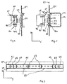
- Bei der in Fig. 1 mit Blickrichtung (y-Richtung senkrecht zur Zeichenebene) horizontal und senkrecht zur Fahrtrichtung x skizzierten Anordnung sind wesentliche Bestandteile einer vorteilhaften Ausführung einer erfindungsgemäßen Heckleuchtenanordnung skizziert. Ausgegangen wird von einem fahrzeugseitigen Träger als z. B. einer an sich gebräuchlichen Quertraverse QT in Form eines mehrfach abgewinkelten Stahlblechs, welche gegenüber einer hinteren Schlussebene ES eine nach hinten offene Vertiefung VT in Fahrtrichtung x aufweist. Es ist an sich gebräuchlich, in dieser Vertiefung Leuchtengehäuse einer Heckleuchtenanordnung unterzubringen und über Anschlussleitungen mit einem heckseitigen Verteiler zu verbinden. Der Träger kann in anderer vorteilhafter Ausführung auch als Aluminium-Strangpressprofil oder als extrudiertes Kunststoffprofil ausgeführt sein.
- Wesentlich an der vorliegenden Erfindung ist, dass in Längsrichtung y des Trägers ein Flachkabel FK mit einer Mehrzahl von Kabeladern KA verläuft, an welches mehrere Leuchtengehäuse LG mittels Kontaktanordnungen KV in der Weise anschließbar sind, dass in an sich bekannter Weise Kontaktspitzen oder Schneidklemmen der Kontaktanordnung in definierter, der vertikalen (y) Positionsverteilung der Kabeladern im Flachkabel entsprechender Position durch die Isolierung des Flachkabels eingedrückt werden und die einzelnen Kabeladern KA dabei kontaktieren. Kontakte der Kontaktanordnung sind innerhalb des Leuchtengehäuses zu den dort vorliegenden Leuchtmitteln weiter verbunden. Das Flachkabel FK weist im skizzierten Beispiel sieben Adern entsprechend einer für alle Leuchtenstromkreise gemeinsamen Masseader und sechs Funktionsadern zu den Stromkreisen der jeweils funktional unabhängigen Beleuchtungsfunktionen auf. Die Kontaktanordnung KV besitzt im skizzierten Beispiel lediglich drei Kontakte, wodurch beispielsweise in ein und demselben Leuchtengehäuse zwei unterschiedliche Beleuchtungsfunktionen, beispielsweise Rücklicht und Bremsleuchte vorliegen und zwei unabhängige Stromkreise mit einer gemeinsamen Masseleitung und zwei separaten Funktionsleitungen versorgt werden können. Die Position der übrigen, bei anderen Leuchtenfunktionen vorzusehenden Kontakte der Kontaktanordnung KV sind durch die unterbrochenen Ausrichtungslinien angedeutet.
- Das Flachkabel FK ist im skizzierten Beispiel mit trapezförmigem Querschnitt in eine Kabelaufnahme AU einer Befestigungsleiste BP leicht klemmend eingefügt oder auch eingeklebt. Die Befestigungsleiste kann insbesondere als Strangpressprofil aus Kunststoff oder Aluminium ausgeführt sein. Durch die Kabelaufnahme AU befindet sich das Flachkabel FK in definierter Position bezüglich der Befestigungsleiste BP. Vorteilhafterweise können an Befestigungsleiste und Leuchtengehäuse korrespondierende Strukturen und Gegenstrukturen zur definierten Ausrichtung des Leuchtengehäuses in z-Richtung, d. h. quer zur Längsrichtung des Flachkabels vorgesehen sein, welche im skizzierten Beispiel als Zentriernut ZN in der Befestigungsleiste und als Zentriervorsprung ZV am Leuchtengehäuse ausgeführt sind. Eine Zentrierung kann auch über eine entsprechende Form des Flachkabels, welches dann vorteilhafterweise über die Befestigungsleiste in Richtung des Leuchtengehäuses vorsteht, und eine entsprechende Formaussparung in der Kontaktanordnung KV erfolgen.
- Bei metallischer Befestigungsleiste BP ist durch entsprechende Bemessungen sicher zu stellen, dass die Kontakte der Kontaktanordnung KV nicht durch das gesamte Flachkabel FK hindurch bis zur metallischen Rückwand gelangen und dort Kurzschlüsse verursachen.
- Die Befestigungsleiste BP weist zusätzlich erste Befestigungsstrukturen BS1, beispielsweise Bohrungen oder hinterschnittene Nuten oder auch nur Wandungen, welche durch selbstbohrende und selbstschneidende Schrauben durchdrungen werden können zur Befestigung der Befestigungsleiste BP an der Wand VW der Vertiefung VT in der Quertraverse QT auf. Korrespondierende Öffnungen O1 können in der Wand VW der Vertiefung VT der Quertraverse QT vorgesehen sein. Die ersten Befestigungsstrukturen an der Befestigungsleiste BP sind vorteilhafterweise in Längsrichtung y der Befestigungsleiste durchgehend vorhanden, insbesondere in Form von hinterschnittenen Nuten, in welche Schraubenköpfe oder Muttern längsverschiebbar eingesetzt werden können.
- An zweiten Befestigungsstrukturen BS2 der Befestigungsleiste BP werden Leuchtengehäuse LG über Befestigungselemente BG befestigt, wobei mit der Befestigung der Leuchtengehäuse auf der Befestigungsleiste zugleich der elektrische Anschluss zwischen den Kontakten der Kontaktanordnung KV und den jeweiligen Kabeladern hergestellt wird. Das Flachkabel FK ist dabei an der Rückwand der Kabelaufnahme AU abgestützt. Die zweiten Befestigungsvorrichtungen können beispielsweise einfach durchgehende Profilwandungen der Befestigungsleiste BP sein, in welche selbstbohrende und schneidende Schrauben als Befestigungselemente BG eingedreht werden. In anderer Ausführung können die zweiten Befestigungsvorrichtungen auch Schnapp- oder Rastverbindungen enthalten.
- Die relativen Ausrichtungen von Befestigungsstrukturen zwischen Befestigungsleiste BP und Quertraverse QT einerseits und Leuchtengehäuse LG andererseits sind jeweils durch unterbrochene Linien angedeutet.
- In Fig. 2 ist eine alternative Ausführungsform skizziert, bei welcher die Kontaktanordnungen KVA nicht fest mit Leuchtengehäusen verbunden sind. Die Kontaktanordnungen sind in diesem Fall an Adaptermodulen AM vorgesehen, welche auf der Befestigungsschiene BP befestigt werden und ihrerseits Befestigungsvorrichtungen BA zur Befestigung von Leuchtengehäusen LS aufweisen. Der elektrische Anschluss der Leuchten in den Leuchtengehäusen LS erfolgt über elektrische Anschlussleitungen, welche mit den jeweils benötigten Kontakten des Adaptermoduls verbunden sind. Um die Adaptermodule für Leuchtengehäuse LS unterschiedlicher Funktion einheitlich verwenden zu können, weisen die Kontaktanordnungen KVA der Adaptermodule einen vollständigen Kontaktsatz zur Kontaktierung aller Adern des Flachkabels FK auf. Für die jeweils benötigte Beleuchtungsfunktion werden dann lediglich die zugehörigen Kontakte der Kontaktanordnung KVA mit den Leitungen des Anschlusskabels AK verbunden.
- In vorteilhafter Ausführung können die Kontaktanordnungen zu einem Leuchtengehäuse bzw. einem Adapter zwei in Längsrichtung y beabstandete gleiche Kontaktreihen enthalten, deren entsprechende Kontakte intern miteinander verbunden sind. Hierdurch kann u. U. die Zuverlässigkeit der Kontaktierung der Kabeladern verbessert werden.
- In Fig. 3 ist mit Blickrichtung in Fahrtrichtung des Fahrzeugs eine Heckleuchtenanordnung in einer Vertiefung VT einer Quertraverse QT skizziert, wobei mit unterbrochener Linie das über im wesentlichen die gesamte Fahrzeugbreite durchgehende Flachkabel FK angedeutet ist. Die Heckleuchtenanordnung enthält mehrere Leuchtengehäuse, insbesondere separate Leuchtengehäuse für Blinker links BL, für Blinker rechts BR, für Rücklicht und Bremslicht RB beidseitig, für Rückfahrscheinwerfer RF und für Nebelschlussleuchte NL sowie für Kennzeichenbeleuchtung KB, welche jeweils separat an der Quertraverse oder einer an dieser befestigten Befestigungsleiste entsprechend BP nach Fig. 1 oder einem Adaptermodul nach Fig. 2 gehalten sind und mittels die Isolierung des Flachkabels durchdringender Kontaktanordnungen mit den für die jeweilige Beleuchtungsfunktion zugeordneten Adern des Flachkabels kontaktiert sind. Größere Lücken zwischen einzelnen Leuchtengehäusen, insbesondere zwischen der mittig angeordneten Kennzeichenbeleuchtung KB und den Enden der Quertraverse zugewandt angeordneten übrigen Leuchtengehäusen können durch optisch passive Blenden DB, welche auch Reflektoren enthalten oder bedruckt sein können, abgedeckt werden, wodurch das Flachkabel in diesen Bereichen zusätzlich geschützt ist.
- In Fig. 4 ist eine zusammen gesetzte Heckleuchtenanordnung mit Blickrichtung in y-Richtung skizziert, bei welcher der Träger als Strangpressprofil SP aus Aluminium ausgeführt sei. In der dem Leuchtengehäuse LG4 zugewandten Wand GW des Profils ist eine Vertiefung vorgesehen, in welcher das Flachkabel FK einliegt. Das Kabel kann durch Randvorsprünge der Vertiefung mechanisch gehalten oder in die Vertiefung eingeklebt sein. Das Leuchtengehäuse LG4 ist direkt auf dem Träger befestigt. Eine Kontaktanordnung KV4 an der dem Kabel zugewandten Seite des Leuchtengehäuses kontaktiert in zu Fig. 1 oder Fig. 2 beschriebener Weise die relevanten oder alle Kabeladern des Flachkabels.
- In Fig. 5 ist eine Heckleuchtenanordnung skizziert, bei welcher die Kontaktanordnung einen Grundkörper GK und einen Deckel DE enthält, welche unter klemmendem Einschluss des Flachkabels in x-Richtung gegeneinander verspannbar sind. Der Grundkörper GK ist auf der dem Leuchtengehäuse LG5 zugewandten und der Deckel DE auf der dem Leuchtengehäuse abgewandten Seite des Flachkabels angeordnet. Die vergrößerte Bautiefe in x-Richtung wird in dem Träger dadurch berücksichtigt, dass in der Trägerwand GW5 des Trägers QT5 eine Öffnung AU vorgesehen ist, durch welche zumindest der Deckel der zusammengesetzten Kontaktanordnung hindurch ragt. Die Verspannung zwischen Grundkörper GK und Deckel DE kann zugleich zur Befestigung des Leuchtengehäuses an dem Träger dienen, wenn der Deckel auf der dem Leuchtengehäuse abgewandten Seite der Trägerwand über die Ränder der Aussparung hinaus ragt. In der Trägerwand GW kann eine Vertiefung GV zur formschlüssigen Aufnahme des Flachkabels vorgesehen sein.
- In Fig. 6 ist eine weitere Ausführungsform skizziert, in welcher die Kontaktanordnung aus einem Grundkörper GK6 und einem Deckel DE6 besteht, zwischen welchen das Flachkabel eingeklemmt ist. Das Flachkabel KT weist in diesem Beispiel die Kabeladern in zwei in x-Richtung voneinander beabstandeten Adernebenen E1 und E2 auf. Adern der Adernebene E1 werden über Kontakte im Grundkörper GK6, Adern in der Adernebene E2 über Kontakte im Deckel DE6 kontaktiert. Von den Kontakten im Deckel DE6 führen elektrische Verbindungsleitungen VL, welche Steckverbindungen oder flexible Kabelabschnitte enthalten können, zu dem Leuchtengehäuse LG6. Das Flachkabel KT verlaufe in dieser Ausführung außerhalb der Wandaussparung AU auf der dem Leuchtengehäuse abgewandten Seite der Wand GW6 des Trägers QT.
- Die vorstehend und die in den Ansprüchen angegebenen sowie die den Abbildungen entnehmbaren Merkmale sind sowohl einzeln als auch in verschiedener Kombination vorteilhaft realisierbar. Die Erfindung ist nicht auf die beschriebenen Ausführungsbeispiele beschränkt, sondern im Rahmen fachmännischen Könnens in mancherlei Weise abwandelbar.
Claims (19)
- Heckleuchtenanordnung an einem Fahrzeug, insbesondere einem Lastfahrzeug mit einem quer zur Fahrtrichtung verlaufenden Träger und mehreren in Längsrichtung des Trägers beabstandeten Einzelleuchten in jeweils eigenen Leuchtengehäusen sowie einer Kabelanordnung zur elektrischen Versorgung der Einzelleuchten, dadurch gekennzeichnet, dass die Kabelanordnung ein Flachkabel enthält, welches sich parallel zur Längsrichtung des Trägers erstreckt und über seine gesamte Länge isolierte Kabeladern für wenigstens zwei unterschiedliche Beleuchtungsfunktionen enthält und dass wenigstens zwei getrennte Leuchtengehäuse mittels die Isolierung durchringender Kontaktanordnungen ohne Unterbrechung von Kabeladern mit Kabeladern kontaktiert und an dem Träger befestigt sind.
- Anordnung nach Anspruch 1, dadurch gekennzeichnet, dass das Flachkabel an einer formstabilen Profilschiene gehalten ist.
- Anordnung nach Anspruch 2 oder 2, dadurch gekennzeichnet, dass eine Befestigungsleiste zur Befestigung der Leuchtengehäuse parallel zum Flachkabel verläuft.
- Anordnung nach Anspruch 2 oder 3, dadurch gekennzeichnet, dass Profilschiene und Befestigungsleiste eine bauliche Einheit bilden.
- Anordnung nach Anspruch 3 oder 4, dadurch gekennzeichnet, dass die Befestigungsleiste in Längsrichtung durchgehende Befestigungsvorrichtungen zur Verbindung mit Leuchtengehäusen und/oder mit dem Träger aufweist.
- Anordnung nach einem der Ansprüche 3 bis 5, dadurch gekennzeichnet, dass die Befestigungsleiste auf dem Träger befestigt ist.
- Anordnung nach Anspruch 1, dadurch gekennzeichnet, dass Flachkabel und Gehäuse unmittelbar auf dem Träger befestigt sind.
- Anordnung nach einem der Ansprüche 1 bis 7, dadurch gekennzeichnet, dass der Träger durch eine Quertraverse am Heck des Fahrzeugs gebildet ist.
- Anordnung nach Anspruch 1 bis 7, dadurch gekennzeichnet, dass das Flachkabel im wesentlichen über die gesamte Fahrzeugbreite verläuft.
- Anordnung nach einem der Ansprüche 1 bis 9, dadurch gekennzeichnet, dass der Träger über einer hinteren Radabdeckung angeordnet ist.
- Anordnung nach einem der Ansprüche 1 bis 10, dadurch gekennzeichnet, dass die Kontaktanordnungen fest mit dem Leuchtengehäuse verbunden sind.
- Anordnung nach Anspruch 11, dadurch gekennzeichnet, dass die Kontaktanordnungen zugleich zur Befestigung der Leuchtengehäuse auf dem Träger oder der Befestigungsleiste dienen.
- Anordnung nach Anspruch 11 oder 12, dadurch gekennzeichnet, dass die Kontaktanordnungen über flexible Leitungen mit den Leuchtengehäusen verbunden sind.
- Anordnung nach einem der Ansprüche 1 bis 13, dadurch gekennzeichnet, dass eine Kontaktanordnung einen Grundkörper auf der dem Gehäuse zugewandten und einen mit dem Grundkörper lösbar verbundenen Deckel auf der dem Gehäuse abgewandten Seite des Flachkabels enthält und das Kabel zwischen Grundkörper und Deckel eingeklemmt ist.
- Anordnung nach Anspruch 14, dadurch gekennzeichnet, dass im Deckel Kontakte zur Kontaktierung von Kabeladern vorgesehen sind und elektrische Verbindungen von diesen Kontakten zum Leuchtengehäuse führen.
- Anordnung nach Anspruch 14, dadurch gekennzeichnet, dass die Kabeladern des Flachkabels in zwei Ebenen angeordnet sind.
- Anordnung nach einem der Ansprüche 1 bis 16, dadurch gekennzeichnet, dass Adaptermodule vorgesehen sind, welche die Kontaktanordnungen aufweisen und auf dem Träger bzw. der Befestigungsleiste befestigbar sind und ihrerseits Befestigungsvorrichtungen und Kabelanschlussvorrichtungen für Leuchtengehäuse enthalten.
- Anordnung nach einem der Ansprüche 1 bis 17, dadurch gekennzeichnet, dass mehrere getrennte Leuchtengehäuse zu wenigstens zwei unterschiedlichen Beleuchtungsfunktionen an ein gemeinsames Flachkabel angeschlossen sind.
- Anordnung nach einem der Ansprüche 1 bis 18, dadurch gekennzeichnet, dass das Flachkabel wenigstens fünf getrennte Kabeladern aufweist.
Applications Claiming Priority (1)
| Application Number | Priority Date | Filing Date | Title |
|---|---|---|---|
| DE102004043083A DE102004043083A1 (de) | 2004-09-07 | 2004-09-07 | Heckleuchtenanordnung |
Publications (2)
| Publication Number | Publication Date |
|---|---|
| EP1632392A1 true EP1632392A1 (de) | 2006-03-08 |
| EP1632392B1 EP1632392B1 (de) | 2007-10-17 |
Family
ID=35385706
Family Applications (1)
| Application Number | Title | Priority Date | Filing Date |
|---|---|---|---|
| EP05016920A Expired - Lifetime EP1632392B1 (de) | 2004-09-07 | 2005-08-04 | Heckleuchtenanordnung |
Country Status (4)
| Country | Link |
|---|---|
| EP (1) | EP1632392B1 (de) |
| AT (1) | ATE375892T1 (de) |
| DE (2) | DE102004043083A1 (de) |
| ES (1) | ES2296019T3 (de) |
Cited By (1)
| Publication number | Priority date | Publication date | Assignee | Title |
|---|---|---|---|---|
| CN104590391A (zh) * | 2014-12-09 | 2015-05-06 | 新兴能源装备股份有限公司 | 一种车辆后防护栏挡泥装置 |
Citations (5)
| Publication number | Priority date | Publication date | Assignee | Title |
|---|---|---|---|---|
| DE1950886A1 (de) * | 1968-10-22 | 1970-04-23 | M A D Les Montages Et Assembla | Befestigungsmittel fuer rueckwaertige Signale an Fahrzeugen |
| US5025350A (en) * | 1990-04-25 | 1991-06-18 | Federal-Mogul Corporation | Vehicle clearance lamp assembly |
| EP0689961A2 (de) * | 1994-06-27 | 1996-01-03 | Reiner Hirschle | Kraftfahrzeugbeleuchtungsanordnung und Verfahren zu ihrem Anbringen und Anschliessen |
| DE10159064A1 (de) * | 2001-12-01 | 2003-06-12 | Hella Kg Hueck & Co | Fahrzeugleuchte |
| US20040156205A1 (en) * | 2003-02-10 | 2004-08-12 | Pisciotti Richard J. | Lighting and safety unit for trailer hitch |
Family Cites Families (4)
| Publication number | Priority date | Publication date | Assignee | Title |
|---|---|---|---|---|
| US5264997A (en) * | 1992-03-04 | 1993-11-23 | Dominion Automotive Industries Corp. | Sealed, inductively powered lamp assembly |
| NL1001182C2 (nl) * | 1995-09-13 | 1997-03-20 | Felua Groep | Verlichtingsarmatuur voor een voertuig. |
| DE20109961U1 (de) * | 2001-06-15 | 2001-08-30 | Röpcke, Hans, 22765 Hamburg | Schlußleuchteneinheit für Nutzfahrzeuge |
| DE202004008372U1 (de) * | 2004-05-26 | 2004-07-22 | Pozzi, Carlo Maurizio | Einrichtung zur Befestigung eines Lastenträgers am Heck eines Fahrzeugs |
-
2004
- 2004-09-07 DE DE102004043083A patent/DE102004043083A1/de not_active Withdrawn
-
2005
- 2005-08-04 AT AT05016920T patent/ATE375892T1/de active
- 2005-08-04 DE DE502005001708T patent/DE502005001708D1/de not_active Expired - Lifetime
- 2005-08-04 EP EP05016920A patent/EP1632392B1/de not_active Expired - Lifetime
- 2005-08-04 ES ES05016920T patent/ES2296019T3/es not_active Expired - Lifetime
Patent Citations (5)
| Publication number | Priority date | Publication date | Assignee | Title |
|---|---|---|---|---|
| DE1950886A1 (de) * | 1968-10-22 | 1970-04-23 | M A D Les Montages Et Assembla | Befestigungsmittel fuer rueckwaertige Signale an Fahrzeugen |
| US5025350A (en) * | 1990-04-25 | 1991-06-18 | Federal-Mogul Corporation | Vehicle clearance lamp assembly |
| EP0689961A2 (de) * | 1994-06-27 | 1996-01-03 | Reiner Hirschle | Kraftfahrzeugbeleuchtungsanordnung und Verfahren zu ihrem Anbringen und Anschliessen |
| DE10159064A1 (de) * | 2001-12-01 | 2003-06-12 | Hella Kg Hueck & Co | Fahrzeugleuchte |
| US20040156205A1 (en) * | 2003-02-10 | 2004-08-12 | Pisciotti Richard J. | Lighting and safety unit for trailer hitch |
Cited By (2)
| Publication number | Priority date | Publication date | Assignee | Title |
|---|---|---|---|---|
| CN104590391A (zh) * | 2014-12-09 | 2015-05-06 | 新兴能源装备股份有限公司 | 一种车辆后防护栏挡泥装置 |
| CN104590391B (zh) * | 2014-12-09 | 2017-06-13 | 新兴能源装备股份有限公司 | 一种车辆后防护栏挡泥装置 |
Also Published As
| Publication number | Publication date |
|---|---|
| DE102004043083A1 (de) | 2006-03-09 |
| ATE375892T1 (de) | 2007-11-15 |
| EP1632392B1 (de) | 2007-10-17 |
| ES2296019T3 (es) | 2008-04-16 |
| DE502005001708D1 (de) | 2007-11-29 |
Similar Documents
| Publication | Publication Date | Title |
|---|---|---|
| DE4101418C2 (de) | Schalterbetätigte Warnleuchte zur Verwendung bei Fahrzeugen | |
| DE69005597T2 (de) | Verbesserung für Multiplex-Steuergeräte für eine Anordnung elektrischer Elemente in einem Kraftfahrzeug. | |
| DE102004062039B3 (de) | Elektrische Steckdose | |
| DE69013221T2 (de) | Hilfsplatine am Armaturenbrett eines Kraftfahrzeugs. | |
| DE202012012607U1 (de) | Signalleuchte für Fahrzeuge | |
| DE202009010108U1 (de) | Leuchte für einen Fachboden eines Möbels | |
| DE4422393C2 (de) | Kraftfahrzeugbeleuchtungsanordnung und Verfahren zu ihrer Anbringung | |
| DE19837314B4 (de) | Vorrichtung für den Masseanschluß elektrischer Komponenten | |
| EP1632392B1 (de) | Heckleuchtenanordnung | |
| EP3876364B1 (de) | Schienenleuchtensystem | |
| DE4409183A1 (de) | Meßinstrumentenmodul und dessen elektrische Verbindungsvorrichtung | |
| DE102007051410A1 (de) | Trägerrohr für Deckenelemente | |
| DE19502928A1 (de) | Blinkleuchtenanordnung für Kraftfahrzeuge | |
| EP2892784A1 (de) | Leuchte für fahrzeuge, insbesondere schienenfahrzeuge | |
| DE69413177T2 (de) | Scheinwerfer für Kraftfahrzeuge | |
| DE102004036340A1 (de) | Heckleuchtenanordnung für Lastfahrzeuge, insbesondere Anhänger | |
| DE102006007101A1 (de) | Heckleuchtenanordnung, insbesondere für Nutzfahrzeuge | |
| DE4447719C2 (de) | Kabelführungsgehäuse | |
| EP1621409A2 (de) | Beleuchtungsanordnung eines Lastfahrzeugs, insbesondere eines Anhängers, sowie Kabelverbinder hierfür | |
| EP3234459B1 (de) | Modulare beleuchtungseinrichtung | |
| EP1690735B1 (de) | Fahrzeugleuchtenanordnung | |
| DE102010027658B4 (de) | Starkstrom-Elektrogehäuse und Anordnung von Starkstrom-Elektrogehäusen | |
| DE102016114232A1 (de) | Beleuchtungsvorrichtung für ein Fahrzeug | |
| DE102017221695B4 (de) | Beleuchtungsanordnung für ein Kraftfahrzeug und Kraftfahrzeug | |
| DE102016218677A1 (de) | Beleuchtungsvorrichtung für ein Kraftfahrzeug |
Legal Events
| Date | Code | Title | Description |
|---|---|---|---|
| PUAI | Public reference made under article 153(3) epc to a published international application that has entered the european phase |
Free format text: ORIGINAL CODE: 0009012 |
|
| AK | Designated contracting states |
Kind code of ref document: A1 Designated state(s): AT BE BG CH CY CZ DE DK EE ES FI FR GB GR HU IE IS IT LI LT LU LV MC NL PL PT RO SE SI SK TR |
|
| AX | Request for extension of the european patent |
Extension state: AL BA HR MK YU |
|
| RAP1 | Party data changed (applicant data changed or rights of an application transferred) |
Owner name: KOMPLED GMBH & CO. KG |
|
| 17P | Request for examination filed |
Effective date: 20060908 |
|
| AKX | Designation fees paid |
Designated state(s): AT BE BG CH CY CZ DE DK EE ES FI FR GB GR HU IE IS IT LI LT LU LV MC NL PL PT RO SE SI SK TR |
|
| GRAP | Despatch of communication of intention to grant a patent |
Free format text: ORIGINAL CODE: EPIDOSNIGR1 |
|
| GRAS | Grant fee paid |
Free format text: ORIGINAL CODE: EPIDOSNIGR3 |
|
| GRAA | (expected) grant |
Free format text: ORIGINAL CODE: 0009210 |
|
| AK | Designated contracting states |
Kind code of ref document: B1 Designated state(s): AT BE BG CH CY CZ DE DK EE ES FI FR GB GR HU IE IS IT LI LT LU LV MC NL PL PT RO SE SI SK TR |
|
| REG | Reference to a national code |
Ref country code: GB Ref legal event code: FG4D Free format text: NOT ENGLISH |
|
| REG | Reference to a national code |
Ref country code: CH Ref legal event code: EP |
|
| REG | Reference to a national code |
Ref country code: IE Ref legal event code: FG4D Free format text: LANGUAGE OF EP DOCUMENT: GERMAN |
|
| REF | Corresponds to: |
Ref document number: 502005001708 Country of ref document: DE Date of ref document: 20071129 Kind code of ref document: P |
|
| NLV1 | Nl: lapsed or annulled due to failure to fulfill the requirements of art. 29p and 29m of the patents act | ||
| REG | Reference to a national code |
Ref country code: ES Ref legal event code: FG2A Ref document number: 2296019 Country of ref document: ES Kind code of ref document: T3 |
|
| ET | Fr: translation filed | ||
| PG25 | Lapsed in a contracting state [announced via postgrant information from national office to epo] |
Ref country code: NL Free format text: LAPSE BECAUSE OF FAILURE TO SUBMIT A TRANSLATION OF THE DESCRIPTION OR TO PAY THE FEE WITHIN THE PRESCRIBED TIME-LIMIT Effective date: 20071017 Ref country code: SE Free format text: LAPSE BECAUSE OF FAILURE TO SUBMIT A TRANSLATION OF THE DESCRIPTION OR TO PAY THE FEE WITHIN THE PRESCRIBED TIME-LIMIT Effective date: 20080117 |
|
| GBV | Gb: ep patent (uk) treated as always having been void in accordance with gb section 77(7)/1977 [no translation filed] | ||
| PG25 | Lapsed in a contracting state [announced via postgrant information from national office to epo] |
Ref country code: SI Free format text: LAPSE BECAUSE OF FAILURE TO SUBMIT A TRANSLATION OF THE DESCRIPTION OR TO PAY THE FEE WITHIN THE PRESCRIBED TIME-LIMIT Effective date: 20071017 Ref country code: PL Free format text: LAPSE BECAUSE OF FAILURE TO SUBMIT A TRANSLATION OF THE DESCRIPTION OR TO PAY THE FEE WITHIN THE PRESCRIBED TIME-LIMIT Effective date: 20071017 Ref country code: BG Free format text: LAPSE BECAUSE OF FAILURE TO SUBMIT A TRANSLATION OF THE DESCRIPTION OR TO PAY THE FEE WITHIN THE PRESCRIBED TIME-LIMIT Effective date: 20080117 Ref country code: IS Free format text: LAPSE BECAUSE OF FAILURE TO SUBMIT A TRANSLATION OF THE DESCRIPTION OR TO PAY THE FEE WITHIN THE PRESCRIBED TIME-LIMIT Effective date: 20080217 Ref country code: LT Free format text: LAPSE BECAUSE OF FAILURE TO SUBMIT A TRANSLATION OF THE DESCRIPTION OR TO PAY THE FEE WITHIN THE PRESCRIBED TIME-LIMIT Effective date: 20071017 Ref country code: PT Free format text: LAPSE BECAUSE OF FAILURE TO SUBMIT A TRANSLATION OF THE DESCRIPTION OR TO PAY THE FEE WITHIN THE PRESCRIBED TIME-LIMIT Effective date: 20080317 Ref country code: LV Free format text: LAPSE BECAUSE OF FAILURE TO SUBMIT A TRANSLATION OF THE DESCRIPTION OR TO PAY THE FEE WITHIN THE PRESCRIBED TIME-LIMIT Effective date: 20071017 |
|
| REG | Reference to a national code |
Ref country code: IE Ref legal event code: FD4D |
|
| PG25 | Lapsed in a contracting state [announced via postgrant information from national office to epo] |
Ref country code: DK Free format text: LAPSE BECAUSE OF FAILURE TO SUBMIT A TRANSLATION OF THE DESCRIPTION OR TO PAY THE FEE WITHIN THE PRESCRIBED TIME-LIMIT Effective date: 20071017 Ref country code: CZ Free format text: LAPSE BECAUSE OF FAILURE TO SUBMIT A TRANSLATION OF THE DESCRIPTION OR TO PAY THE FEE WITHIN THE PRESCRIBED TIME-LIMIT Effective date: 20071017 |
|
| PLBE | No opposition filed within time limit |
Free format text: ORIGINAL CODE: 0009261 |
|
| STAA | Information on the status of an ep patent application or granted ep patent |
Free format text: STATUS: NO OPPOSITION FILED WITHIN TIME LIMIT |
|
| PG25 | Lapsed in a contracting state [announced via postgrant information from national office to epo] |
Ref country code: RO Free format text: LAPSE BECAUSE OF FAILURE TO SUBMIT A TRANSLATION OF THE DESCRIPTION OR TO PAY THE FEE WITHIN THE PRESCRIBED TIME-LIMIT Effective date: 20071017 Ref country code: SK Free format text: LAPSE BECAUSE OF FAILURE TO SUBMIT A TRANSLATION OF THE DESCRIPTION OR TO PAY THE FEE WITHIN THE PRESCRIBED TIME-LIMIT Effective date: 20071017 |
|
| 26N | No opposition filed |
Effective date: 20080718 |
|
| PG25 | Lapsed in a contracting state [announced via postgrant information from national office to epo] |
Ref country code: IE Free format text: LAPSE BECAUSE OF FAILURE TO SUBMIT A TRANSLATION OF THE DESCRIPTION OR TO PAY THE FEE WITHIN THE PRESCRIBED TIME-LIMIT Effective date: 20071017 |
|
| PG25 | Lapsed in a contracting state [announced via postgrant information from national office to epo] |
Ref country code: GB Free format text: LAPSE BECAUSE OF FAILURE TO SUBMIT A TRANSLATION OF THE DESCRIPTION OR TO PAY THE FEE WITHIN THE PRESCRIBED TIME-LIMIT Effective date: 20071017 |
|
| PG25 | Lapsed in a contracting state [announced via postgrant information from national office to epo] |
Ref country code: GR Free format text: LAPSE BECAUSE OF FAILURE TO SUBMIT A TRANSLATION OF THE DESCRIPTION OR TO PAY THE FEE WITHIN THE PRESCRIBED TIME-LIMIT Effective date: 20080118 |
|
| PG25 | Lapsed in a contracting state [announced via postgrant information from national office to epo] |
Ref country code: FI Free format text: LAPSE BECAUSE OF FAILURE TO SUBMIT A TRANSLATION OF THE DESCRIPTION OR TO PAY THE FEE WITHIN THE PRESCRIBED TIME-LIMIT Effective date: 20071017 |
|
| PG25 | Lapsed in a contracting state [announced via postgrant information from national office to epo] |
Ref country code: MC Free format text: LAPSE BECAUSE OF NON-PAYMENT OF DUE FEES Effective date: 20080831 |
|
| PG25 | Lapsed in a contracting state [announced via postgrant information from national office to epo] |
Ref country code: EE Free format text: LAPSE BECAUSE OF FAILURE TO SUBMIT A TRANSLATION OF THE DESCRIPTION OR TO PAY THE FEE WITHIN THE PRESCRIBED TIME-LIMIT Effective date: 20071017 |
|
| PG25 | Lapsed in a contracting state [announced via postgrant information from national office to epo] |
Ref country code: CY Free format text: LAPSE BECAUSE OF FAILURE TO SUBMIT A TRANSLATION OF THE DESCRIPTION OR TO PAY THE FEE WITHIN THE PRESCRIBED TIME-LIMIT Effective date: 20071017 Ref country code: BE Free format text: LAPSE BECAUSE OF NON-PAYMENT OF DUE FEES Effective date: 20080831 |
|
| PGFP | Annual fee paid to national office [announced via postgrant information from national office to epo] |
Ref country code: ES Payment date: 20090821 Year of fee payment: 5 |
|
| REG | Reference to a national code |
Ref country code: CH Ref legal event code: PL |
|
| PG25 | Lapsed in a contracting state [announced via postgrant information from national office to epo] |
Ref country code: CH Free format text: LAPSE BECAUSE OF NON-PAYMENT OF DUE FEES Effective date: 20090831 Ref country code: LI Free format text: LAPSE BECAUSE OF NON-PAYMENT OF DUE FEES Effective date: 20090831 |
|
| PG25 | Lapsed in a contracting state [announced via postgrant information from national office to epo] |
Ref country code: HU Free format text: LAPSE BECAUSE OF FAILURE TO SUBMIT A TRANSLATION OF THE DESCRIPTION OR TO PAY THE FEE WITHIN THE PRESCRIBED TIME-LIMIT Effective date: 20080418 Ref country code: LU Free format text: LAPSE BECAUSE OF NON-PAYMENT OF DUE FEES Effective date: 20080804 |
|
| PG25 | Lapsed in a contracting state [announced via postgrant information from national office to epo] |
Ref country code: TR Free format text: LAPSE BECAUSE OF FAILURE TO SUBMIT A TRANSLATION OF THE DESCRIPTION OR TO PAY THE FEE WITHIN THE PRESCRIBED TIME-LIMIT Effective date: 20071017 |
|
| PGFP | Annual fee paid to national office [announced via postgrant information from national office to epo] |
Ref country code: AT Payment date: 20100820 Year of fee payment: 6 Ref country code: DE Payment date: 20100831 Year of fee payment: 6 Ref country code: FR Payment date: 20100901 Year of fee payment: 6 |
|
| PG25 | Lapsed in a contracting state [announced via postgrant information from national office to epo] |
Ref country code: IT Free format text: LAPSE BECAUSE OF NON-PAYMENT OF DUE FEES Effective date: 20080831 |
|
| REG | Reference to a national code |
Ref country code: ES Ref legal event code: FD2A Effective date: 20111019 |
|
| PG25 | Lapsed in a contracting state [announced via postgrant information from national office to epo] |
Ref country code: ES Free format text: LAPSE BECAUSE OF NON-PAYMENT OF DUE FEES Effective date: 20100805 |
|
| REG | Reference to a national code |
Ref country code: FR Ref legal event code: ST Effective date: 20120430 |
|
| REG | Reference to a national code |
Ref country code: DE Ref legal event code: R119 Ref document number: 502005001708 Country of ref document: DE Effective date: 20120301 |
|
| PG25 | Lapsed in a contracting state [announced via postgrant information from national office to epo] |
Ref country code: FR Free format text: LAPSE BECAUSE OF NON-PAYMENT OF DUE FEES Effective date: 20110831 |
|
| REG | Reference to a national code |
Ref country code: AT Ref legal event code: MM01 Ref document number: 375892 Country of ref document: AT Kind code of ref document: T Effective date: 20110804 |
|
| PG25 | Lapsed in a contracting state [announced via postgrant information from national office to epo] |
Ref country code: AT Free format text: LAPSE BECAUSE OF NON-PAYMENT OF DUE FEES Effective date: 20110804 |
|
| PG25 | Lapsed in a contracting state [announced via postgrant information from national office to epo] |
Ref country code: DE Free format text: LAPSE BECAUSE OF NON-PAYMENT OF DUE FEES Effective date: 20120301 |