EP1632373B1 - Système de climatisation pour véhicule avec mode autonome - Google Patents
Système de climatisation pour véhicule avec mode autonome Download PDFInfo
- Publication number
- EP1632373B1 EP1632373B1 EP05016540A EP05016540A EP1632373B1 EP 1632373 B1 EP1632373 B1 EP 1632373B1 EP 05016540 A EP05016540 A EP 05016540A EP 05016540 A EP05016540 A EP 05016540A EP 1632373 B1 EP1632373 B1 EP 1632373B1
- Authority
- EP
- European Patent Office
- Prior art keywords
- refrigerant
- engine
- compressor
- fan
- vehicle
- Prior art date
- Legal status (The legal status is an assumption and is not a legal conclusion. Google has not performed a legal analysis and makes no representation as to the accuracy of the status listed.)
- Expired - Lifetime
Links
Images


Classifications
-
- B—PERFORMING OPERATIONS; TRANSPORTING
- B60—VEHICLES IN GENERAL
- B60H—ARRANGEMENTS OF HEATING, COOLING, VENTILATING OR OTHER AIR-TREATING DEVICES SPECIALLY ADAPTED FOR PASSENGER OR GOODS SPACES OF VEHICLES
- B60H1/00—Heating, cooling or ventilating devices
- B60H1/32—Cooling devices
- B60H1/3204—Cooling devices using compression
- B60H1/3227—Cooling devices using compression characterised by the arrangement or the type of heat exchanger, e.g. condenser, evaporator
-
- B—PERFORMING OPERATIONS; TRANSPORTING
- B60—VEHICLES IN GENERAL
- B60H—ARRANGEMENTS OF HEATING, COOLING, VENTILATING OR OTHER AIR-TREATING DEVICES SPECIALLY ADAPTED FOR PASSENGER OR GOODS SPACES OF VEHICLES
- B60H1/00—Heating, cooling or ventilating devices
- B60H1/00457—Ventilation unit, e.g. combined with a radiator
-
- F—MECHANICAL ENGINEERING; LIGHTING; HEATING; WEAPONS; BLASTING
- F25—REFRIGERATION OR COOLING; COMBINED HEATING AND REFRIGERATION SYSTEMS; HEAT PUMP SYSTEMS; MANUFACTURE OR STORAGE OF ICE; LIQUEFACTION SOLIDIFICATION OF GASES
- F25B—REFRIGERATION MACHINES, PLANTS OR SYSTEMS; COMBINED HEATING AND REFRIGERATION SYSTEMS; HEAT PUMP SYSTEMS
- F25B2400/00—General features or devices for refrigeration machines, plants or systems, combined heating and refrigeration systems or heat-pump systems, i.e. not limited to a particular subgroup of F25B
- F25B2400/07—Details of compressors or related parts
- F25B2400/075—Details of compressors or related parts with parallel compressors
Definitions
- the invention relates to a motor vehicle stationary air conditioner according to the preamble of claim 1.
- US 3 719 058 shows a stationary air conditioning according to the preamble of claim 1.
- a motor vehicle stationary air conditioning system is provided with a refrigerant circuit in which at least one compressor is arranged, which may be a mechanical and / or an electric compressor, which circulates the refrigerant in the refrigerant circuit.
- a first and a second air-cooled condenser for cooling the refrigerant coming from the compressor is arranged, wherein two fans are provided.
- a fan is mechanically by means of the motor vehicle engine and a fan is electrically driven.
- a fan may be provided with a hybrid drive, which is both mechanically and electrically driven.
- the two different drivable fan are each arranged on a capacitor.
- two capacitors are provided, wherein at least one fan is arranged on each capacitor, which differs in the drive from that of the fan associated with the other capacitor.
- the capacitors can be designed according to the operating state in which the respective fan is in operation, so that an optimization of the cooling capacity is possible.
- the capacitors are connected according to the invention in series or in series operation in series operation.
- the first capacitor is preferably cooled by a mechanically driven fan and the second capacitor is cooled by an electrically driven fan.
- a bypass is provided around the first and / or second capacitor. If a condenser is flowed through by refrigerant, it is a certain cooling, even if the fan is, however, the drive power required by the compressor is greater due to the larger flow resistance with a flow through the capacitor, so that the provision of a bypass is at least useful, when the energy gain by the reduced flow resistance is greater than the energy gain by the cooling capacity of the condenser without air flow.
- the condenser can, with appropriate design in the case of an at least partial flow in the stand mode, in which usually less refrigerant is needed, preferably also as a collector or as an additional collector, i. if one or more other collectors are provided in the refrigerant circuit, serve.
- the motor vehicle stationary air conditioning system which comprises a front and a rear air conditioner, preferably has at least two refrigerant circuits.
- the refrigerant circuits may in this case preferably be connected to one another, so that in particular during normal operation only one refrigerant circuit and in standby mode two separate refrigerant circuits are provided.
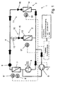
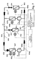
- the power supply is indicated in all figures by dash-dot lines.
- the two compressors 5 and 6 are arranged in parallel branches of the refrigerant circuit 4.
- a check valve (not shown) is arranged in the corresponding branch of the refrigerant circuit 4 in the refrigerant flow direction after the second compressor 6.
- a corresponding check valve may also be provided in the other branch after the first compressor 5.
- the air is conveyed by a first fan 8 driven by the motor vehicle engine through the condenser 7.
- a first collector 9 for collecting and temporarily storing excess liquid refrigerant is arranged.
- the refrigerant circuit 4 is then followed by a distribution of the refrigerant to two the respective air conditioner 2 and 3 respectively associated branches 10 and 11, wherein in the front air conditioner 2 associated branch 10, a valve 12 can shut off the flow of refrigerant.
- the refrigerant before it reaches the respective evaporator 13 or 14, flows through an expansion element 15 or 16 in which it expands and is thereby cooled.
- Each of the evaporator 13 and 14 is associated with an electrically driven blower 17 and 18, which promotes the air through the evaporator 13 and 14 and the motor vehicle interior in the respective climate zone. After flowing through the evaporator 13 and 14, the refrigerant streams are reunited and return to the first compressor 5 in normal operation.
- stationary mode that is, when the motor vehicle engine is stopped, the circulation of the refrigerant takes place exclusively through the second, electrically driven compressor 6.
- the hot refrigerant flows through the condenser 7, with no air due to the stationary motor and the first fan 8 thus standing is promoted by the same.
- a second fan 8 ' is provided, which is actuated electrically in a stationary mode, so that a sufficient cooling capacity is ensured by the capacitor 7.
- the further course corresponds to that of normal operation, with the refrigerant returning to the second compressor 6 due to the stationary first compressor 5.
- the second fan 8 ' it is operated parallel to the first fan 8 with a particularly large cooling requirement.
- the control can be done in particular depending on the refrigerant temperature and / or ambient temperature dependent and / or engine speed dependent.
- the refrigerant circuit 104 is substantially similar to that of the first Cooling circuit constructed so that the same and equivalent components are provided with higher by 100 reference numerals than the first cooling circuit.
- the parallel connection of the two compressors 105 and 106 corresponds to the previously described arrangement.
- a first capacitor 107 is arranged, which is traversed by air in normal operation, which is supported by a mechanically driven fan 108. This is followed by a first collector 109.
- a second capacitor 107 ' which is flowed through in the stationary mode of air, which is supported by an electrically driven fan 108'. This is followed by a second collector 109 '.
- the further course corresponds to that of the refrigerant circuit 4 of the first cooling circuit, so that will not be discussed in detail.
- the collectors 109, 109 ' allow optimized collection of excess refrigerant in the area where it is liquid and from where it can be quickly fed back to the refrigerant circuit when needed.
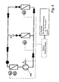
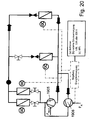
- the first, in Fig. 3 illustrated embodiment of the invention substantially corresponds to the second cooling circuit described above, so that will be discussed below only the differences.
- a branch with a bypass around the second condenser 207 'and second header 209' is provided after the first header 209, wherein the control is effected by means of a respective valve which is arranged in the two parallel branches.
- the bypass leads to the second collector 209 '.
- the valve in front of the second condenser 207 ' is closed and the valve is open in the bypass, so that the entire refrigerant is conducted past the second condenser 207'.
- the valve in front of the second condenser 207 ' is opened and the other valve closed, so that the refrigerant flows through the second condenser 207 'and the second collector 209'.
- the second fan 208 ' is actuated while the first normally-driven motor 208 is inoperative due to the stationary motor, so that the second condenser 207' in communication with the second fan 208 'cools the refrigerant takes over.
- cooling circuit are not provided differently driven compressors 5 and 6, in contrast to the first cooling circuit, but it is only an electrically driven compressor 306 is provided which circulates the refrigerant as needed both in normal operation and in standby mode. Otherwise, the fourth cooling circuit corresponds to the first cooling circuit, so that will not be discussed in more detail below.
- Fig. 5 shows the fifth cooling circuit, which is substantially the second cooling circuit of Fig. 2
- an electric compressor 406 is provided, which circulates the refrigerant both in normal operation and in stationary operation.
- FIG. 6 illustrated second embodiment of the invention substantially corresponds to the in Fig. 3 illustrated, the first embodiment, in turn, comparable to the previous cooling circuit, only an electric compressor 506 is provided, which circulates the refrigerant both in normal operation and in standby mode.
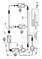
- the refrigerant circuit 604 can be divided by means of valves 620, 621 into a refrigerant circuit 604a for the front air conditioner 602 and a refrigerant circuit 604b for the rear air conditioner 603, in which in each case an electrically drivable compressor 606a, 606b and a capacitor 607a, 607b are arranged.
- the separation by the valves 620, 621 enables optimized, needs-based cooling, especially in standby mode.
- the compressor 606a disposed in the front refrigerant circuit 604a circulates the refrigerant in the refrigerant circuit 604. From the compressor 606a, the refrigerant flows to the condenser 607, to which a mechanically driven first fan 608a and a normally operating, electrically driven second fan 608a 'are arranged, and to the collector 609. Subsequently, the refrigerant flow is split, with a part through one branch 610 and the other part flows through branch 611. In branch 610, an expansion element 615 is arranged in front of an evaporator 613.
- a second expansion element 616 is correspondingly arranged in front of a second evaporator 614. Subsequently, the two branches 610 and 611 are brought together again, so that the refrigerant returns to the compressor 606a.
- the two valves 620 and 621 are closed, forming two independent refrigerant circuits 604a and 604b, each circulated by an electrically driven compressor 606a and 606b.
- the refrigerant circuit 604a in the stand mode which is associated with the front air conditioner 602, corresponds - apart from the rear air conditioner 603 associated part - that of normal operation, wherein instead of powered by the motor vehicle engine fan 608 of the electrically driven fan 608 'provides for air flow through the capacitor 607 , After the condenser 607, the cooled refrigerant passes through the collector 609, the expansion member 615, where it is further cooled as a result of the pressure drop, and the evaporator 613 before returning to the compressor 606a.
- the standby mode refrigerant cycle 604b is circulated by the electrically driven compressor 606b, wherein the hot refrigerant is cooled in a condenser 607b, for which air conveyed by an electric fan 608b is passed through the condenser 607b.
- no collector is disposed after the condenser 607b, but a collector may be provided.
- the cooled refrigerant flows through the expander 616 and the evaporator 614 before returning to the compressor 606b.
- the eighth refrigeration cycle shown differs from the previously described seventh refrigeration cycle only in that instead of the electrically driven compressor 606a, a hybrid compressor 705a / 706a is provided, which can be electrically driven by the engine and the other.
- Fig. 9 shows the ninth cooling circuit, which essentially corresponds to the first cooling circuit, but instead of two mutually parallel compressors 5 and 6 has a hybrid compressor 805/806, which is driven by the motor vehicle engine and in standby mode by means of electrical energy in normal operation , With respect to the operation of the fans 808 and 808 'should be referred to the first cooling circuit.
- the in Fig. 10 shown tenth cooling circuit substantially corresponds to the second cooling circuit, wherein instead of two mutually parallel compressors 105 and 106 corresponding to the previously described ninth cooling circuit, a hybrid compressor 905/906 is provided.
- FIG. 11 illustrated third embodiment of the invention substantially corresponds to the first embodiment, wherein instead of two compressors arranged parallel to each other corresponding to the ninth cooling circuit described above, a hybrid compressor 1005/1006 is provided.
- the refrigerant preferably accumulates in standby mode in certain components, in particular in a parallel and non-operating compressor in excess, resulting in a drop in cooling capacity and possibly also to a failure of the compressors can lead, since in standby mode, just as much refrigerant is present as in normal operation, but due to the lower required cooling capacity actually much less refrigerant is needed, appropriate measures to reduce the amount of refrigerant in standby mode are to make sense.
- This is done according to the present third embodiment, characterized in that in the standby mode, a defined amount of refrigerant from the refrigerant circuit via a bypass (not shown) is sucked off and stored. As soon as it is switched to normal operation, the refrigerant is pumped back into the refrigerant circuit.
- the electric compressor is not operated continuously but only at intervals.
- a refrigerant accumulator with variable capacity is provided in the refrigerant circuit. In this case, an integration of expansion element in a collector and dryer unit is possible, so that instead of the two expansion organs of the first embodiment, corresponding combinations are provided.
- a bypass with an ice storage is provided in the refrigerant circuit, in which the excess (cold) refrigerant is introduced, the brine cools, and dwells during stand-by operation in this bypass.
- At least part of the condenser which is not flowed through by cooling air in stationary operation, can serve as an intermediate storage for the excess refrigerant.
- a bypass corresponding to the provided in various embodiments bypass around the second capacitor, may be provided for the first capacitor to the first capacitor.
- the control is carried out accordingly by means of two arranged in the two branches valves.
- a bypass only makes sense if, in an operating state, the fan associated with the bypass bypassed by means of the bypass is not driven.
- a hybrid drive for a fan may be provided in the previously described embodiments, in which two different drivable fan are arranged on a capacitor, which replaces the two fans.
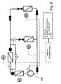
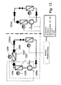
- Fig. 12 12 shows a twelfth cooling circuit, according to which two completely separate refrigerant circuits 1104a and 1104b are provided, this cooling circuit corresponding to the seventh embodiment with the valves 620 and 621 closed. However, according to the twelfth refrigeration cycle, the two compressors 1106a and 1106b are electrically driven both in normal operation and in standby mode.
- a second condenser 1207 'and a second header 1209' are arranged in the first refrigerant circuit 1204a after the electric driven compressor 1206a, the first condenser 1207 and the first header 1209, each condenser a fan is provided, in this case at the first capacitor 1207, a mechanically, driven by the motor vehicle engine first fan 1208, which is driven in normal operation, and the second capacitor 1207 ', a second, electrically driven fan 1208', which is driven in stand mode.
- the second refrigerant circuit 1204b corresponds to the refrigerant circuit 1104b.
- a hybrid compressor 1305a / 1306a in the first refrigerant circuit 1304a is provided in place of the electrically driven compressor 1206a.
- the second refrigerant circuit 1304b corresponds to the refrigerant circuit 1104b of the twelfth refrigeration cycle.
- an automotive air conditioning system is according to one of the examples described in a truck or truck with a separated from the cab or the cab area, such as a sleeping cabin used, with a front air conditioner in the cab is located and a rear or rear air conditioner in the separated area of the vehicle.
- a branch is provided after the merger of the two parallel branches with the compressors 1405 and 1406, wherein a first, lockable by a first valve branch forms a bypass to the second, lockable by a second valve branch, in which the first capacitor 1407, through which air with the aid of the mechanically driven fan 1408 can be promoted, is arranged.
- the first valve is closed and the second valve is open, so that the refrigerant flows through the second branch and thus through the condenser 1407.
- the second capacitor 1407 ' in contrast to the first embodiment, no bypass is provided. Further, only after the second condenser 1407 ', through which air can be delivered by means of the electrically driven fan 1408', is the accumulator 1409 arranged, i. the first collector 209 according to the first embodiment is omitted according to the present embodiment.
- the air from a first, driven by the motor vehicle engine fan 1408 with open second valve and closed first valve through the condenser 1407 promoted.
- the cooling is also due to the airstream.
- the cooled refrigerant flows through the second Capacitor 1407 ', with electrically driven second fan 1408', and accumulator 1409.
- a distribution of the refrigerant then takes place on two branches 10 and 11 assigned to the respective air conditioner 2 or 3, wherein in the branch 10 associated with the front air conditioner 2, a valve 12 can shut off the refrigerant flow.
- the refrigerant before it reaches the respective evaporator 13 or 14, flows through an expansion element 15 or 16, in which it expands and is thereby cooled.
- Each of the evaporators 13 and 14 is associated with an electrically driven blower 17 and 18, which promotes the air through the evaporator 13 and 14 and the motor vehicle interior in the respective climate zone. After flowing through the evaporator 13 and 14, the refrigerant streams are reunited and return to the first compressor 1405 in normal operation.
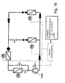
- Fig. 16 illustrated fifth embodiment of the invention, instead of the parallel branches with mechanically driven compressor 1405 and electrically driven compressor 1406 only an electrically driven compressor 1506 is provided, which circulates the refrigerant when needed both in normal operation and in standby mode.
- an electrically driven compressor 1506 is provided, which circulates the refrigerant when needed both in normal operation and in standby mode.
- a mechanically drivable by the engine corresponding to the compressor 1405 and electrically, according to the compressor 1406 drivable hybrid compressor 1605/1606 is provided, which in normal operation of the current motor vehicle engine and is powered in standby mode with the help of batteries, an external power supply or an APU.
- the fourth cooling circuit With regard to the other normal and stand operation, reference is again made to the description of the fourth cooling circuit.
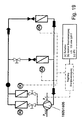
- an electric compressor 1706 is provided for circulating the refrigerant, which is driven both in normal operation and in the stationary mode.
- the further embodiment of the refrigerant circuit 1704 corresponds to that of the previously described cooling circuit, so that will not be discussed in detail.
- the refrigerant is circulated by the electric compressor 1706 and flows through the first branch, in which the first condenser 1707 is disposed, due to the open first valve and the closed second valve. This is traversed by air, which is promoted by the mechanically driven by the running motor fan 1708.
- the electrically driven fan 1708 'on the second capacitor 1707' is.
- the refrigerant flows through the collector 1709.
- the first valve In stand mode, i. when the engine is stopped, the first valve is closed and the second valve open, so that the hot refrigerant flows only through the second condenser 1707 '. In this case, it is traversed by air, which is conveyed by the electrically driven second fan 1708 ', whereas the mechanically drivable first fan 1708 is stationary. Subsequently, the refrigerant flows through the collector 1709. With regard to the further course of the flow, reference is again made to the description of the first cooling circuit.
- a hybrid compressor 1805/1806 is provided, which is electrically driven in normal operation by the running engine and in the stationary mode. Otherwise, the nineteenth cooling circuit coincides with the eighteenth cooling circuit described above.
- the cooling circuit shown is provided with a parallel circuit of a mechanical compressor 1905 and an electric compressor 1906 instead of the electric compressor 1706 of the eighteenth cooling circuit. Otherwise, the twentieth refrigeration cycle coincides with the eighteenth refrigeration cycle.
Landscapes
- Physics & Mathematics (AREA)
- Thermal Sciences (AREA)
- Engineering & Computer Science (AREA)
- Mechanical Engineering (AREA)
- Air-Conditioning For Vehicles (AREA)
Claims (7)
- Système de climatisation autonome pour véhicules automobiles, comprenant un circuit (4) de fluide frigorigène dans lequel est disposé au moins un compresseur (5, 6 ; 105, 106 ; 506 ; 1005 / 1006 ; 1405, 1406 ; 1506 ; 1605 / 1606) qui fait circuler le fluide frigorigène dans le circuit (4 ; 104 ; 1404) de fluide frigorigène, où un premier condenseur (107, 107'; 207, 207'; 1407, 1407') à refroidissement à air servant au refroidissement du fluide frigorigène provenant du compresseur (5, 6 ; 105, 106 ; 506 ; 1005 / 1006 ; 1405, 1406 ; 1506 ; 1605 / 1606), et un deuxième condenseur (107, 107' ; 207', 207 ; 1407, 1407') à refroidissement à air, sont disposés dans le circuit (4 ; 104 ; 1404) de fluide frigorigène, où les condenseurs sont montés en série et, au cours d'un fonctionnement en mode autonome, peuvent être montés en série, et il est prévu deux ventilateurs (208, 208' ; 808, 808' ; 1408, 1408') où un ventilateur (208 ; 808 ; 1408) peut être actionné mécaniquement à l'aide du moteur du véhicule automobile et un ventilateur (208' ; 808' ; 1408') peut être actionné électriquement, et les deux ventilateurs (208, 208' ; 808, 808' ; 1408, 1408') pouvant être actionnés de façon différente sont disposés chacun sur un condenseur (107, 107' 207', 207 ; 1407, 1407'),
caractérise en ce qu'il est prévu une dérivation autour du premier et / ou du deuxième condenseur (107, 107' ; 207', 207 ; 1407, 1407'). - Système de climatisation autonome pour véhicules automobiles selon la revendication 1, caractérisé en ce que le premier condenseur (107, 107' 207, 207' ; 1407, 1407') communique avec un ventilateur (208 ; 1208 ; 1408) pouvant être actionné mécaniquement, le deuxième condenseur (107, 107' ; 207, 207' ; 1407, 1407') communique avec un ventilateur (208' ; 1208' ; 1408') pouvant être actionné électriquement.
- Système de climatisation autonome pour véhicules automobiles selon l'une ou l'autre des revendications précédentes, caractérisé en ce que, au cours du fonctionnement en mode autonome, les deux condenseurs (107, 107' ; 207, 207' ; 1407, 1407') sont traversés au moins partiellement par du fluide frigorigène, où seulement l'un des condenseurs (107, 107' ; 207, 207' ; 1407, 1407') est refroidi par un flux d'air.
- Système de climatisation autonome pour véhicules automobiles selon la revendication 3, caractérisé en ce que le condenseur traversé seulement de façon partielle, au cours du fonctionnement en mode autonome, sert de collecteur supplémentaire pour du fluide frigorigène.
- Système de climatisation autonome pour véhicules automobiles selon l'une quelconque des revendications précédentes, caractérisé en ce qu'un collecteur (209, 209') est disposé à la suite de chacun des condenseurs (107, 107' ; 207, 207' ; 1407, 1407').
- Système de climatisation autonome pour véhicules automobiles selon l'une quelconque des revendications précédentes, caractérisé en ce que le système de climatisation autonome pour véhicules automobiles présente au moins deux circuits de fluide frigorigène.
- Système de climatisation autonome pour véhicules automobiles selon l'une quelconque des revendications précédentes, caractérisé en ce que le système de climatisation autonome pour véhicules automobiles présente un circuit de fluide frigorigène qui peut être divisé en deux circuits de fluide frigorigène indépendants, où au moins un compresseur est disposé dans chacun des circuits de fluide frigorigène.
Applications Claiming Priority (2)
| Application Number | Priority Date | Filing Date | Title |
|---|---|---|---|
| DE102004042679 | 2004-09-01 | ||
| US11/107,012 US7290400B2 (en) | 2004-09-01 | 2005-04-15 | Stationary vehicle air conditioning system and method |
Publications (2)
| Publication Number | Publication Date |
|---|---|
| EP1632373A1 EP1632373A1 (fr) | 2006-03-08 |
| EP1632373B1 true EP1632373B1 (fr) | 2011-06-15 |
Family
ID=35432068
Family Applications (1)
| Application Number | Title | Priority Date | Filing Date |
|---|---|---|---|
| EP05016540A Expired - Lifetime EP1632373B1 (fr) | 2004-09-01 | 2005-07-29 | Système de climatisation pour véhicule avec mode autonome |
Country Status (1)
| Country | Link |
|---|---|
| EP (1) | EP1632373B1 (fr) |
Families Citing this family (2)
| Publication number | Priority date | Publication date | Assignee | Title |
|---|---|---|---|---|
| WO2013041897A1 (fr) * | 2011-09-23 | 2013-03-28 | Renault Trucks | Procédé propre à améliorer l'efficacité d'un système de climatisation pour habitacle de véhicule |
| DE102024101651A1 (de) * | 2024-01-22 | 2025-07-24 | Bayerische Motoren Werke Aktiengesellschaft | Kompressionskältemaschine und klimaeinrichtung zur standklimatisierung für ein kraftfahrzeug |
Family Cites Families (7)
| Publication number | Priority date | Publication date | Assignee | Title |
|---|---|---|---|---|
| US3719058A (en) * | 1971-03-16 | 1973-03-06 | Cummins Engine Co Inc | Vehicle air conditioning apparatus |
| DE3345340C2 (de) * | 1983-12-15 | 1985-11-28 | Daimler-Benz Ag, 7000 Stuttgart | Antrieb für das Kühlluftgebläse einer Brennkraftmaschine |
| DE4324071A1 (de) * | 1993-07-17 | 1995-01-19 | Audi Ag | Vorrichtung zur Kühlluftführung |
| DE4414547A1 (de) | 1994-04-26 | 1995-11-02 | Konvekta Ag | Fahrzeug-Standklimaanlage |
| JPH11301255A (ja) * | 1998-04-22 | 1999-11-02 | Toyota Autom Loom Works Ltd | 車両用空調装置 |
| DE10065279C1 (de) * | 2000-12-29 | 2002-07-04 | Webasto Thermosysteme Gmbh | Vorrichtung zur Klimatisierung eines Fahrzeuginnenraums |
| DE10242369B4 (de) * | 2002-09-12 | 2007-09-13 | Webasto Ag | Klimatisierungssystem für ein Kraftfahrzeug, insbesondere ein Hybridfahrzeug |
-
2005
- 2005-07-29 EP EP05016540A patent/EP1632373B1/fr not_active Expired - Lifetime
Also Published As
| Publication number | Publication date |
|---|---|
| EP1632373A1 (fr) | 2006-03-08 |
Similar Documents
| Publication | Publication Date | Title |
|---|---|---|
| EP3454401B1 (fr) | Véhicule automobile pourvu d'un système de refroidissement | |
| EP0504653B1 (fr) | Méthode pour la réfrigeration des composants de l'entraînement ainsi que pour le chauffage de l'habitacle d'un véhicule automobile en particulier électrique et dispositif pour la mise en oeuvre de la méthode | |
| EP2519415B1 (fr) | Système de climatisation pour un véhicule et procédé de thermorégulation | |
| DE102015220623B4 (de) | Wärmesystem für ein Elektro- oder Hybridfahrzeug | |
| DE102015103032B4 (de) | Wärmeverteilungsvorrichtung für ein Fahrzeug | |
| EP1961593B1 (fr) | Climatisation pour véhicule | |
| EP1961592B1 (fr) | Climatisation pour véhicule | |
| DE112020004318T5 (de) | Anschlussmodul | |
| DE10343225B3 (de) | System zum Heizen und Kühlen eines Innenraums eines Fahrzeugs | |
| EP1499511B1 (fr) | Installation de climatisation | |
| DE102020117471A1 (de) | Wärmepumpenanordnung mit indirekter Batterieerwärmung für batteriebetriebene Kraftfahrzeuge und Verfahren zum Betreiben einer Wärmepumpenanordnung | |
| DE102013216927A1 (de) | Fahrzeugwärmepumpensystem für milde Umgebung | |
| DE102015218824A1 (de) | Wärmepumpensystem und Verfahren zum Betrieb eines solchen | |
| DE102012113103A1 (de) | Wärmepumpensystem für Fahrzeug und Verfahren zum Steuern desselben | |
| DE102014100632A1 (de) | Fahrzeug-Wärmepumpensystem und -verfahren, das eine Zwischengasrekompression verwendet | |
| WO2017005559A1 (fr) | Circuit frigorifique, procédé de climatisation d'un véhicule et véhicule | |
| DE102015016241B4 (de) | Elektrisch angetriebenes Fahrzeug mit einem Kühlsystem | |
| DE202006009803U1 (de) | Verdampfungskühlanordnung für Fahrzeuge | |
| EP1632374A1 (fr) | Système de climatisation pour véhicule avec mode autonome | |
| DE102008005076A1 (de) | Kältemittelkreis und Verfahren zum Betreiben eines Kältemittelkreises | |
| DE9202466U1 (de) | Einrichtung zur Kühlung von Antriebskomponenten und zur Heizung eines Fahrgastraumes eines Kraftfahrzeuges, insbesondere eines Elektromobils | |
| EP1632373B1 (fr) | Système de climatisation pour véhicule avec mode autonome | |
| WO2023061686A1 (fr) | Dispositif de commande de température pour un véhicule automobile | |
| DE102005036350A1 (de) | Kraftfahrzeug-Standklimaanlage | |
| EP1632372B1 (fr) | Système de climatisation pour véhicule avec mode autonome |
Legal Events
| Date | Code | Title | Description |
|---|---|---|---|
| PUAI | Public reference made under article 153(3) epc to a published international application that has entered the european phase |
Free format text: ORIGINAL CODE: 0009012 |
|
| AK | Designated contracting states |
Kind code of ref document: A1 Designated state(s): AT BE BG CH CY CZ DE DK EE ES FI FR GB GR HU IE IS IT LI LT LU LV MC NL PL PT RO SE SI SK TR |
|
| AX | Request for extension of the european patent |
Extension state: AL BA HR MK YU |
|
| 17P | Request for examination filed |
Effective date: 20060908 |
|
| 17Q | First examination report despatched |
Effective date: 20061012 |
|
| AKX | Designation fees paid |
Designated state(s): AT BE BG CH CY CZ DE DK EE ES FI FR GB GR HU IE IS IT LI LT LU LV MC NL PL PT RO SE SI SK TR |
|
| GRAP | Despatch of communication of intention to grant a patent |
Free format text: ORIGINAL CODE: EPIDOSNIGR1 |
|
| GRAS | Grant fee paid |
Free format text: ORIGINAL CODE: EPIDOSNIGR3 |
|
| GRAA | (expected) grant |
Free format text: ORIGINAL CODE: 0009210 |
|
| AK | Designated contracting states |
Kind code of ref document: B1 Designated state(s): AT BE BG CH CY CZ DE DK EE ES FI FR GB GR HU IE IS IT LI LT LU LV MC NL PL PT RO SE SI SK TR |
|
| REG | Reference to a national code |
Ref country code: GB Ref legal event code: FG4D Free format text: NOT ENGLISH Ref country code: CH Ref legal event code: EP |
|
| REG | Reference to a national code |
Ref country code: IE Ref legal event code: FG4D Free format text: LANGUAGE OF EP DOCUMENT: GERMAN |
|
| REG | Reference to a national code |
Ref country code: DE Ref legal event code: R096 Ref document number: 502005011491 Country of ref document: DE Effective date: 20110728 |
|
| REG | Reference to a national code |
Ref country code: NL Ref legal event code: VDEP Effective date: 20110615 |
|
| PG25 | Lapsed in a contracting state [announced via postgrant information from national office to epo] |
Ref country code: LT Free format text: LAPSE BECAUSE OF FAILURE TO SUBMIT A TRANSLATION OF THE DESCRIPTION OR TO PAY THE FEE WITHIN THE PRESCRIBED TIME-LIMIT Effective date: 20110615 Ref country code: SE Free format text: LAPSE BECAUSE OF FAILURE TO SUBMIT A TRANSLATION OF THE DESCRIPTION OR TO PAY THE FEE WITHIN THE PRESCRIBED TIME-LIMIT Effective date: 20110615 |
|
| PG25 | Lapsed in a contracting state [announced via postgrant information from national office to epo] |
Ref country code: GR Free format text: LAPSE BECAUSE OF FAILURE TO SUBMIT A TRANSLATION OF THE DESCRIPTION OR TO PAY THE FEE WITHIN THE PRESCRIBED TIME-LIMIT Effective date: 20110916 Ref country code: CY Free format text: LAPSE BECAUSE OF FAILURE TO SUBMIT A TRANSLATION OF THE DESCRIPTION OR TO PAY THE FEE WITHIN THE PRESCRIBED TIME-LIMIT Effective date: 20110615 Ref country code: LV Free format text: LAPSE BECAUSE OF FAILURE TO SUBMIT A TRANSLATION OF THE DESCRIPTION OR TO PAY THE FEE WITHIN THE PRESCRIBED TIME-LIMIT Effective date: 20110615 Ref country code: FI Free format text: LAPSE BECAUSE OF FAILURE TO SUBMIT A TRANSLATION OF THE DESCRIPTION OR TO PAY THE FEE WITHIN THE PRESCRIBED TIME-LIMIT Effective date: 20110615 Ref country code: SI Free format text: LAPSE BECAUSE OF FAILURE TO SUBMIT A TRANSLATION OF THE DESCRIPTION OR TO PAY THE FEE WITHIN THE PRESCRIBED TIME-LIMIT Effective date: 20110615 |
|
| PG25 | Lapsed in a contracting state [announced via postgrant information from national office to epo] |
Ref country code: NL Free format text: LAPSE BECAUSE OF FAILURE TO SUBMIT A TRANSLATION OF THE DESCRIPTION OR TO PAY THE FEE WITHIN THE PRESCRIBED TIME-LIMIT Effective date: 20110615 |
|
| REG | Reference to a national code |
Ref country code: IE Ref legal event code: FD4D |
|
| BERE | Be: lapsed |
Owner name: BEHR G.M.B.H. & CO. KG Effective date: 20110731 |
|
| PG25 | Lapsed in a contracting state [announced via postgrant information from national office to epo] |
Ref country code: IE Free format text: LAPSE BECAUSE OF FAILURE TO SUBMIT A TRANSLATION OF THE DESCRIPTION OR TO PAY THE FEE WITHIN THE PRESCRIBED TIME-LIMIT Effective date: 20110615 Ref country code: CZ Free format text: LAPSE BECAUSE OF FAILURE TO SUBMIT A TRANSLATION OF THE DESCRIPTION OR TO PAY THE FEE WITHIN THE PRESCRIBED TIME-LIMIT Effective date: 20110615 Ref country code: EE Free format text: LAPSE BECAUSE OF FAILURE TO SUBMIT A TRANSLATION OF THE DESCRIPTION OR TO PAY THE FEE WITHIN THE PRESCRIBED TIME-LIMIT Effective date: 20110615 Ref country code: IS Free format text: LAPSE BECAUSE OF FAILURE TO SUBMIT A TRANSLATION OF THE DESCRIPTION OR TO PAY THE FEE WITHIN THE PRESCRIBED TIME-LIMIT Effective date: 20111015 Ref country code: PT Free format text: LAPSE BECAUSE OF FAILURE TO SUBMIT A TRANSLATION OF THE DESCRIPTION OR TO PAY THE FEE WITHIN THE PRESCRIBED TIME-LIMIT Effective date: 20111017 |
|
| PG25 | Lapsed in a contracting state [announced via postgrant information from national office to epo] |
Ref country code: MC Free format text: LAPSE BECAUSE OF NON-PAYMENT OF DUE FEES Effective date: 20110731 Ref country code: RO Free format text: LAPSE BECAUSE OF FAILURE TO SUBMIT A TRANSLATION OF THE DESCRIPTION OR TO PAY THE FEE WITHIN THE PRESCRIBED TIME-LIMIT Effective date: 20110615 Ref country code: SK Free format text: LAPSE BECAUSE OF FAILURE TO SUBMIT A TRANSLATION OF THE DESCRIPTION OR TO PAY THE FEE WITHIN THE PRESCRIBED TIME-LIMIT Effective date: 20110615 Ref country code: PL Free format text: LAPSE BECAUSE OF FAILURE TO SUBMIT A TRANSLATION OF THE DESCRIPTION OR TO PAY THE FEE WITHIN THE PRESCRIBED TIME-LIMIT Effective date: 20110615 |
|
| REG | Reference to a national code |
Ref country code: CH Ref legal event code: PL |
|
| PLBE | No opposition filed within time limit |
Free format text: ORIGINAL CODE: 0009261 |
|
| STAA | Information on the status of an ep patent application or granted ep patent |
Free format text: STATUS: NO OPPOSITION FILED WITHIN TIME LIMIT |
|
| PG25 | Lapsed in a contracting state [announced via postgrant information from national office to epo] |
Ref country code: LI Free format text: LAPSE BECAUSE OF NON-PAYMENT OF DUE FEES Effective date: 20110731 Ref country code: BE Free format text: LAPSE BECAUSE OF NON-PAYMENT OF DUE FEES Effective date: 20110731 Ref country code: CH Free format text: LAPSE BECAUSE OF NON-PAYMENT OF DUE FEES Effective date: 20110731 |
|
| 26N | No opposition filed |
Effective date: 20120316 |
|
| GBPC | Gb: european patent ceased through non-payment of renewal fee |
Effective date: 20110915 |
|
| PG25 | Lapsed in a contracting state [announced via postgrant information from national office to epo] |
Ref country code: IT Free format text: LAPSE BECAUSE OF FAILURE TO SUBMIT A TRANSLATION OF THE DESCRIPTION OR TO PAY THE FEE WITHIN THE PRESCRIBED TIME-LIMIT Effective date: 20110615 |
|
| PG25 | Lapsed in a contracting state [announced via postgrant information from national office to epo] |
Ref country code: DK Free format text: LAPSE BECAUSE OF FAILURE TO SUBMIT A TRANSLATION OF THE DESCRIPTION OR TO PAY THE FEE WITHIN THE PRESCRIBED TIME-LIMIT Effective date: 20110615 |
|
| REG | Reference to a national code |
Ref country code: DE Ref legal event code: R097 Ref document number: 502005011491 Country of ref document: DE Effective date: 20120316 |
|
| PG25 | Lapsed in a contracting state [announced via postgrant information from national office to epo] |
Ref country code: GB Free format text: LAPSE BECAUSE OF NON-PAYMENT OF DUE FEES Effective date: 20110915 |
|
| REG | Reference to a national code |
Ref country code: AT Ref legal event code: MM01 Ref document number: 512816 Country of ref document: AT Kind code of ref document: T Effective date: 20110729 |
|
| PG25 | Lapsed in a contracting state [announced via postgrant information from national office to epo] |
Ref country code: AT Free format text: LAPSE BECAUSE OF NON-PAYMENT OF DUE FEES Effective date: 20110729 |
|
| PG25 | Lapsed in a contracting state [announced via postgrant information from national office to epo] |
Ref country code: ES Free format text: LAPSE BECAUSE OF FAILURE TO SUBMIT A TRANSLATION OF THE DESCRIPTION OR TO PAY THE FEE WITHIN THE PRESCRIBED TIME-LIMIT Effective date: 20110926 |
|
| PG25 | Lapsed in a contracting state [announced via postgrant information from national office to epo] |
Ref country code: LU Free format text: LAPSE BECAUSE OF NON-PAYMENT OF DUE FEES Effective date: 20110729 |
|
| PG25 | Lapsed in a contracting state [announced via postgrant information from national office to epo] |
Ref country code: BG Free format text: LAPSE BECAUSE OF FAILURE TO SUBMIT A TRANSLATION OF THE DESCRIPTION OR TO PAY THE FEE WITHIN THE PRESCRIBED TIME-LIMIT Effective date: 20110915 |
|
| PG25 | Lapsed in a contracting state [announced via postgrant information from national office to epo] |
Ref country code: TR Free format text: LAPSE BECAUSE OF FAILURE TO SUBMIT A TRANSLATION OF THE DESCRIPTION OR TO PAY THE FEE WITHIN THE PRESCRIBED TIME-LIMIT Effective date: 20110615 |
|
| PG25 | Lapsed in a contracting state [announced via postgrant information from national office to epo] |
Ref country code: HU Free format text: LAPSE BECAUSE OF FAILURE TO SUBMIT A TRANSLATION OF THE DESCRIPTION OR TO PAY THE FEE WITHIN THE PRESCRIBED TIME-LIMIT Effective date: 20110615 |
|
| REG | Reference to a national code |
Ref country code: DE Ref legal event code: R082 Ref document number: 502005011491 Country of ref document: DE Representative=s name: GRAUEL, ANDREAS, DIPL.-PHYS. DR. RER. NAT., DE |
|
| REG | Reference to a national code |
Ref country code: DE Ref legal event code: R082 Ref document number: 502005011491 Country of ref document: DE Representative=s name: GRAUEL, ANDREAS, DIPL.-PHYS. DR. RER. NAT., DE Effective date: 20150305 Ref country code: DE Ref legal event code: R081 Ref document number: 502005011491 Country of ref document: DE Owner name: MAHLE INTERNATIONAL GMBH, DE Free format text: FORMER OWNER: BEHR GMBH & CO. KG, 70469 STUTTGART, DE Effective date: 20150305 Ref country code: DE Ref legal event code: R081 Ref document number: 502005011491 Country of ref document: DE Owner name: MAHLE INTERNATIONAL GMBH, DE Free format text: FORMER OWNER: BEHR GMBH & CO. KG, 70469 STUTTGART, DE Effective date: 20110603 |
|
| REG | Reference to a national code |
Ref country code: FR Ref legal event code: PLFP Year of fee payment: 12 |
|
| REG | Reference to a national code |
Ref country code: FR Ref legal event code: PLFP Year of fee payment: 13 |
|
| REG | Reference to a national code |
Ref country code: FR Ref legal event code: PLFP Year of fee payment: 14 |
|
| PGFP | Annual fee paid to national office [announced via postgrant information from national office to epo] |
Ref country code: FR Payment date: 20180724 Year of fee payment: 14 |
|
| PGFP | Annual fee paid to national office [announced via postgrant information from national office to epo] |
Ref country code: DE Payment date: 20190919 Year of fee payment: 15 |
|
| PG25 | Lapsed in a contracting state [announced via postgrant information from national office to epo] |
Ref country code: FR Free format text: LAPSE BECAUSE OF NON-PAYMENT OF DUE FEES Effective date: 20190731 |
|
| REG | Reference to a national code |
Ref country code: DE Ref legal event code: R119 Ref document number: 502005011491 Country of ref document: DE |
|
| PG25 | Lapsed in a contracting state [announced via postgrant information from national office to epo] |
Ref country code: DE Free format text: LAPSE BECAUSE OF NON-PAYMENT OF DUE FEES Effective date: 20210202 |