EP1632309B1 - Vorrichtung zur Bearbeitung mit Gegenspindel in einer Mehrspindeldrehmaschine - Google Patents
Vorrichtung zur Bearbeitung mit Gegenspindel in einer Mehrspindeldrehmaschine Download PDFInfo
- Publication number
- EP1632309B1 EP1632309B1 EP04104282A EP04104282A EP1632309B1 EP 1632309 B1 EP1632309 B1 EP 1632309B1 EP 04104282 A EP04104282 A EP 04104282A EP 04104282 A EP04104282 A EP 04104282A EP 1632309 B1 EP1632309 B1 EP 1632309B1
- Authority
- EP
- European Patent Office
- Prior art keywords
- machining
- counter
- translation
- guiding
- spindle
- Prior art date
- Legal status (The legal status is an assumption and is not a legal conclusion. Google has not performed a legal analysis and makes no representation as to the accuracy of the status listed.)
- Active
Links
- 238000003754 machining Methods 0.000 title claims abstract description 187
- 238000006073 displacement reaction Methods 0.000 claims description 24
- 230000000694 effects Effects 0.000 claims description 11
- 238000000605 extraction Methods 0.000 claims description 7
- 241001080024 Telles Species 0.000 description 7
- 238000005520 cutting process Methods 0.000 description 2
- 238000004519 manufacturing process Methods 0.000 description 2
- 238000011084 recovery Methods 0.000 description 2
- 238000012550 audit Methods 0.000 description 1
- 230000001419 dependent effect Effects 0.000 description 1
- 239000003550 marker Substances 0.000 description 1
- 238000000034 method Methods 0.000 description 1
Images


Classifications
-
- B—PERFORMING OPERATIONS; TRANSPORTING
- B23—MACHINE TOOLS; METAL-WORKING NOT OTHERWISE PROVIDED FOR
- B23Q—DETAILS, COMPONENTS, OR ACCESSORIES FOR MACHINE TOOLS, e.g. ARRANGEMENTS FOR COPYING OR CONTROLLING; MACHINE TOOLS IN GENERAL CHARACTERISED BY THE CONSTRUCTION OF PARTICULAR DETAILS OR COMPONENTS; COMBINATIONS OR ASSOCIATIONS OF METAL-WORKING MACHINES, NOT DIRECTED TO A PARTICULAR RESULT
- B23Q39/00—Metal-working machines incorporating a plurality of sub-assemblies, each capable of performing a metal-working operation
- B23Q39/04—Metal-working machines incorporating a plurality of sub-assemblies, each capable of performing a metal-working operation the sub-assemblies being arranged to operate simultaneously at different stations, e.g. with an annular work-table moved in steps
- B23Q39/042—Metal-working machines incorporating a plurality of sub-assemblies, each capable of performing a metal-working operation the sub-assemblies being arranged to operate simultaneously at different stations, e.g. with an annular work-table moved in steps with circular arrangement of the sub-assemblies
- B23Q39/044—Metal-working machines incorporating a plurality of sub-assemblies, each capable of performing a metal-working operation the sub-assemblies being arranged to operate simultaneously at different stations, e.g. with an annular work-table moved in steps with circular arrangement of the sub-assemblies having at least one tool station cooperating with each work holder, e.g. multi-spindle lathes
-
- B—PERFORMING OPERATIONS; TRANSPORTING
- B23—MACHINE TOOLS; METAL-WORKING NOT OTHERWISE PROVIDED FOR
- B23Q—DETAILS, COMPONENTS, OR ACCESSORIES FOR MACHINE TOOLS, e.g. ARRANGEMENTS FOR COPYING OR CONTROLLING; MACHINE TOOLS IN GENERAL CHARACTERISED BY THE CONSTRUCTION OF PARTICULAR DETAILS OR COMPONENTS; COMBINATIONS OR ASSOCIATIONS OF METAL-WORKING MACHINES, NOT DIRECTED TO A PARTICULAR RESULT
- B23Q39/00—Metal-working machines incorporating a plurality of sub-assemblies, each capable of performing a metal-working operation
- B23Q39/04—Metal-working machines incorporating a plurality of sub-assemblies, each capable of performing a metal-working operation the sub-assemblies being arranged to operate simultaneously at different stations, e.g. with an annular work-table moved in steps
- B23Q39/048—Metal-working machines incorporating a plurality of sub-assemblies, each capable of performing a metal-working operation the sub-assemblies being arranged to operate simultaneously at different stations, e.g. with an annular work-table moved in steps the work holder of a work station transfers directly its workpiece to the work holder of a following work station
-
- B—PERFORMING OPERATIONS; TRANSPORTING
- B23—MACHINE TOOLS; METAL-WORKING NOT OTHERWISE PROVIDED FOR
- B23Q—DETAILS, COMPONENTS, OR ACCESSORIES FOR MACHINE TOOLS, e.g. ARRANGEMENTS FOR COPYING OR CONTROLLING; MACHINE TOOLS IN GENERAL CHARACTERISED BY THE CONSTRUCTION OF PARTICULAR DETAILS OR COMPONENTS; COMBINATIONS OR ASSOCIATIONS OF METAL-WORKING MACHINES, NOT DIRECTED TO A PARTICULAR RESULT
- B23Q2230/00—Special operations in a machine tool
- B23Q2230/006—Machining both ends of a workpiece consecutively
Definitions
- the invention relates to counter-operation machining on a cylinder machine tool and in particular to a device as described in the preamble of claim 1 (see, for example, EP-0936027-A ).
- counter-operation any machining operation performed on a so-called rear portion of a workpiece, after another so-called front portion of said workpiece has been machined in a conventional manner.
- a counter-operation may concern both external machining and internal machining of said rear portion.
- the conventional solution is to resume machining the rear portion of the workpiece on another machine or later on the same machine.
- This solution requires a large handling of the workpieces as well as two machines or greatly increases the production time if only one machine is used for both types of operations.
- a counter-spindle is advanced in front of the front portion of the workpiece, the latter is gripped by the forceps of the counter spindle, then released by the clamp of the main spindle in the case of an automatic lathe or so is cut in the case of a lathe. Then, successively, the counter-spindle is moved back, a counter-operation tool is put in place, the counter-spindle is advanced to the working position, then the counter-operation machining is performed. After this, the counter-spindle is moved back, the tool is released, the counter-spindle clamp is loosened and the workpiece is extracted.
- this solution requires the use of two machining stations on the barrel, thereby limiting the machining stations available for the front portion on this barrel.
- Another solution is to turn the workpiece into the workpiece pin clamp.
- This solution also has disadvantages, namely that possibly several machining stations are to be provided for machining operations on the rear portion of the workpiece, thereby reducing the machining stations available for machining operations. on the front portion.
- WO-A-03/103892 consists in grasping the part when it is in the extraction or cutting position, and then transporting it by an automatic transport means to an auxiliary apparatus on which the machining operations are carried out.
- FR-A-2303626 consists of constructing a symmetrical machine tool, that is to say having two barrels aligned on the same axis, or mounted on the same central slide, a first barrel carrying the workpiece pins for machining the front portions while the second barrel carries the workpiece pins for machining the rear portions, the two barrels bearing the same number of pins and being indexed simultaneously on the common axis.
- a first object that the invention aims to achieve is a counter-operation machining device configuration that frees the machining area of the machine tool and increases its ability to perform many machining on the same part while reducing the time allotted to the production of each piece.
- Another object of the invention is to provide a multispindle machine tool equipped with the aforementioned device.
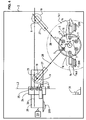
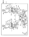
- FIGS. 1 to 6 show a portion 1 of a machine tool 2, particularly around a zone, called a machining zone 3, in which machining operations are performed on parts 9.
- the machine tool 2 is symbolized by a rectangle marked 2.
- the machine tool 2 comprises a structure 200, such as a frame 200, but in the drawings, the frame 200 has not been fully represented and only portions of this frame 200 have been shown schematically. The marker 200 is therefore associated with these portions because of their membership in the frame 200.
- the machine tool 2 is a barrel type lathe 4 and, in the example shown, comprises a feeder device 11 located behind said barrel 4. This association is well known and commonly used.
- the feeder device 11 has also not been shown in detail because it does not affect the invention.
- the barrel 4 carries a plurality of pins 7 each provided with a first clamp 8 intended to clamp a piece 9 constituted by the end of a bar 12, to allow the machining of a front portion 91 of this piece 9, in particular, during the rotation of said part 9 about a second axis 10, the rotation of the barrel 4 around a first axis 6 being, by a motor assembly 40, controlled in a fractional manner, in particular in a first predetermined direction S1, so as to present the pins 9 in front of different machining stations 16 whose angular situations are predefined.
- the part 9 and the end of the bar 12 are not distinct at first, and it is only after completion of a certain number of machining operations that the part 9 is actually removed. in the bar 12.
- the machine tool 2 shown makes it possible to machine parts 9 taken from bars 12, but the invention also applies to the case where parts 9 have been previously loaded into barrel 4.
- each front portion 91 of a part 9 consists of the end of a bar 12 provided by the feeder device 11, said bar 12 being clamped in the first clamp 8, behind the front portion 91 of this part 9.
- machining blocks 14 said front machining blocks 14, each carrying at least one first machining tool 15, are provided for the machining, for example radial, of the front part. at machining stations 16 corresponding to the various pins 7.
- the front machining blocks 14 are, for example, mounted on crossed slides 140.
- front machining blocks 14 each carrying at least one first machining tool 15 displaceable in translation axially to the part 9 by the effect of a jack 17, can be provided for axial machining of the front part. at the same machining stations 16 as those mentioned above.
- the cylinder 17 may be of any known type and, for example, consist of a hydraulic cylinder or a screw jack.
- the first machining tools 15 may be fixed or rotating and may be provided for internal or external machining of the front portion 91 of the part 9.
- Each of the pins 7 may be provided with rotating means 18 which, because of a known type of technique, not shown in detail.
- the indexing of the barrel 4 is carried out by a motor assembly 40 in such a way that, by its rotation in said first predetermined direction S1, the pins 7 which this barrel 4 carries are successively presented at each of the machining stations 16 .
- front machining blocks 14 In the drawing (FIGS. 2 to 6), in order to facilitate the reading, only two front machining blocks 14 have been represented, but in general the machine tool 2 has many others and the presence of these machining blocks. front 14 poses a significant problem for the implementation of one or more rear machining blocks 24.
- the first device for guiding and moving in translation 22 is placed under the influence of a first control device 26 which makes it possible to generate displacements of predetermined values and directions.
- the influence of the first control device 26 on the first device for guiding and displacing in translation 22 is symbolized by a short broken arrow pointing towards the said device for guiding and moving in translation 22.
- the machine tool 2 as described hitherto is conventional and allows multi-station machining of the front parts 91 of the parts 9.
- the machining zone 3 of the machine tool 2 occupies a first substantially cylindrical volume of revolution which is coaxial with the first axis of rotation and includes said second axes of rotation 10 of the plurality of pins 7.
- the machining zone 3 has been represented by a broken fine line to which the mark 3 is associated.
- the front machining blocks 14 are distributed substantially radially around the first cylindrical envelope volume of the machining zone 3 and at the end of this volume, in front of the barrel 4.
- the front machining blocks 14 are therefore part of a second volume of cylindrical envelope 141 coaxial with said first cylindrical volume of the machining zone 3.
- the machine tool 2 intended to be equipped with the device of the invention comprises at least one machining block of a second type, called rear machining block 24, which is provided with at least one second machining tool 25 and is provided to perform at least one machining of the rear portion 92 of a part 9 held by said at least one counter-spindle 19.
- rear machining block 24 which is provided with at least one second machining tool 25 and is provided to perform at least one machining of the rear portion 92 of a part 9 held by said at least one counter-spindle 19.
- the second machining tools can be fixed or rotating and can be provided for internal or external machining of the rear portion 92 of the part 9.
- said at least one counter-spindle 19 is carried by a device for guiding and displacing in translation in a second direction 28 which is radial to the second axis 10 substantially removes said at least one counter-spindle 19 from said second axis 10 to bring it closer to a rear machining block 24 which can be placed in a situation noticeably remote from the machining zone 3 and said second volume 141 in which the front machining blocks 14 are inscribed.
- FIGS. 2 to 6 show a rear machining block 24 which carries second tools 25 for axial or radial machining of the part 9.
- This configuration of the machining device 1 in counter-operation thus frees the machining zone 3 of the machine tool 2 and makes it possible to increase its capacity to perform numerous machining operations on the same part 9.
- This configuration is chosen to avoid any risk of conflict between one of the front machining blocks 14 and said at least one rear machining block 24.
- the second (32) and third (33) indexed control devices 32, 33 are digitally controlled type devices placed under the influence and control of a central control unit not shown, this central control unit also managing, in particular, the operation of the engine assembly 40 of the cylinder 4.
- the aforementioned configuration makes it possible to digitally center each counter spindle 19 carried by a second device for guiding and displacing in translation 27, with respect to a second tool carried by a machining block. back 24.
- said first plane 31 is substantially orthogonal to said second axis of rotation.
- the counter-operation machining device comprises a single counter-spindle 19 carried by a second device for guiding and displacing in translation 27.
- FIG. 1 A first variant of the first embodiment (described above) is shown in FIG. 1
- At least a third direction (30) intersects with at least a second direction (28) (FIGS. 5).
- the invention also relates to a machine tool which comprises at least one machining device 1 against operation as previously defined.
- the indexed control devices, said first control device 26, second control device 32 and third control device 33, are advantageously part of a central control unit of the equipped machine tool 2.
Claims (13)
- Gegenbearbeitungsvorrichtung (1) für eine Werkzeugmaschine (2), die mit Folgendem versehen ist:- mit einem Revolver (4), der eine Mehrzahl von Spindeln (7) hält, von denen jede mit einer ersten Greiferzange (8) versehen ist, die dazu dient, ein Werkstück (9) einzuspannen, um die Bearbeitung eines vorderen Teils (91) dieses Werkstücks (9), insbesondere bei Drehung des genannten Werkstücks (9) um eine zweite Achse (10) zu ermöglichen, wobei die Umdrehung des Revolvers (4) um eine erste Achse (6) durch eine Antriebsbaugruppe (40) nach einer Unterteilung insbesondere in eine erste festgelegte Richtung (S1) betätigt wird, so dass die Spindeln (9) vor unterschiedlichen Bearbeitungsstationen (16) positioniert werden, deren Winkellagen festgelegt sind,- mit mehreren Bearbeitungseinheiten eines ersten Typs, den sogenannten vorderen Bearbeitungseinheiten (14), von den jede mindestens ein erstes Bearbeitungswerkzeug (15) hält und die zur Bearbeitung des genannten vorderen Teils (91) auf mindestens einigen Bearbeitungsstationen (16) bestimmt sind,- mit mindestens einer Gegenspindel (19), die mit einer zweiten Greiferzange (20) versehen ist, welche drehbar um eine dritte Achse (21) montiert von einer ersten translatorischen Führungs- und Verfahrvorrichtung (22) in einer ersten, zur zweiten Achse (10) parallelen Richtung (23) getragen wird, um durch eine translatorische Hin- und Herbewegung die Entnahme eines Werkstücks (9) aus einer festgelegten, gegenüberliegenden Spindel (7) zu gestatten, und dies zum Zweck der späteren Ausführung einer weiteren Bearbeitung durch Halten des genannten Werkstücks (9) an einem hinteren Teil (92), und- mit mindestens einer Bearbeitungseinheit eines zweiten Typs, der sogenannten hinteren Bearbeitungseinheit (24), die mindestens mit einem zweiten Bearbeitungswerkzeug (25) versehen und zur Ausführung von mindestens einer Bearbeitung des hinteren Teils (92) eines Werkstücks (9) bestimmt ist, das von mindestens einer genannten Gegenspindel gehalten wird,wobei diese Gegenbearbeitungsvorrichtung (1) dadurch gekennzeichnet wird, dass:- mindestens eine Gegenspindel (19), die sie aufweist, von einer zweiten translatorischen Führungs- und Verfahrvorrichtung (27) getragen wird, und dies. einerseits so, dass ein von der genannten Gegenspindel (19) erfasstes Werkstück (9) parallel zu sich selbst in eine zweite Richtung (28) verfahren werden kann, die radial zur genannten zweiten Drehachse (10) der Spindel (7) ist, in der sie einen Arbeitsgang zur Nachbearbeitung eines Werkstücks (9) ausführen muss, und. andererseits zwischen mindestens zwei Positionen (P1, P2), die auf dieser zweiten Richtung (28) liegen, darunter eine Position (P1), die sogenannte Entnahmeposition (P1), welche die Entnahme eines Werkstücks (9) aus einer festgelegten, es tragenden Spindel (7) ermöglicht und mindestens eine andere Position (P2), die sogenannte Übergabeposition (P2), die dazu bestimmt ist, die Ausführung einer hinteren Bearbeitung durch ein zweites Bearbeitungswerkzeug (25) zu gestatten, wobei diese Übergabeposition (P2) außerhalb des Bearbeitungsbereiches (3) und der vorderen Bearbeitungseinheiten (14) verlegt wird, und- mindestens eine genannte hintere Bearbeitungseinheit (24) von einer dritten translatorischen Führungs- und Verfahrvorrichtung (29) getragen wird, und dies in einer dritten Richtung (30), die ein einer Ebene, der sogenannten ersten Ebene (31), liegt, welche sich mit der genannten zweiten Drehachse (10) der Spindel (7) schneidet, in der sie einen Arbeitsgang zur Nachbearbeitung eines Werkstücks (9) ausführen muss, wobei die genannte dritte Richtung so zu der genannten zweiten Richtung (28) ausgerichtet ist, dass durch Verfahrbewegungen zur hinteren Bearbeitungseinheit (24) und zur Gegenspindel (19) die Bauteile, diezueinander positioniert werden können, um eine solche Bearbeitung des hinteren Teils (92) des genannten Werkstücks (9) zu gestatten, wenn es in der zweiten Richtung (28) auf mindestens eine Übergabeposition (P2) verfahren wird.. einerseits mindestens ein zur Ausführung von mindestens einer Bearbeitung des hinteren Teils (92) eines in mindestens einer genannten Gegenspindel (19) gehaltenen Werkstücks (9) bestimmtes zweites Bearbeitungswerkzeug (25) und. andererseits mindestens ein solches Werkstück (9) umfassen,
- Gegenbearbeitungsvorrichtung nach Anspruch 1, dadurch gekennzeichnet, dass- sie einerseits Folgendes aufweist:. mindestens eine zweite Antriebsvorrichtung (32) von mindestens einer zweiten translatorischen Führungs- und Verfahrvorrichtung (27) einer Gegenspindel (19) und. mindestens eine dritte Antriebsvorrichtung (33) von mindestens einer dritten translatorischen Führungs- und Verfahrvorrichtung (29) eines zweiten Bearbeitungswerkzeugs (25) und- andererseits die genannte zweite (32) und dritte (33) translatorische Führungs- und Verfahrvorrichtung (32, 33) so entwickelt wurden, dass sie Verfahrbewegungen erzeugen, deren Werte und Richtungen im Voraus festgelegt worden sind.
- Gegenbearbeitungsvorrichtung nach Anspruch 1 oder 2, dadurch gekennzeichnet, dass die genannte erste Ebene (31) im Wesentlichen senkrecht zur genannten zweiten Drehachse (10) steht.
- Gegenbearbeitungsvorrichtung nach einem der Ansprüche 1 bis 3, dadurch gekennzeichnet, dass die Gegenbearbeitungsvorrichtung eine einzige Gegenspindel (19) aufweist, die von einer zweiten translatorischen Führungs- und Verfahrvorrichtung (27) getragen wird.
- Gegenbearbeitungsvorrichtung nach einem der Ansprüche 1 bis 3, dadurch gekennzeichnet, dass sie mindestens eine Gruppe von zwei Gegenspindeln (19) aufweist und:- diese Gegenspindeln (19) von zwei zweiten, verschiedenen translatorischen Führungs- und Verfahrvorrichtungen (27) getragen werden, die so ausgerichtet sind, dass die von ihnen bestimmten zweiten Richtungen (28) radial zu einer einzigen zweiten Drehachse (10) einer Spindel (7) verlaufen, die sich an einer festgelegten Bearbeitungsstation (16) liegt, und- die genannte zweite und dritte Antriebsvorrichtung (32, 33) den Betrieb dieser zweiten, verschiedenen translatorischen Führungs- und Verfahrvorrichtungen (27) so steuern, dass die Gegenspindeln (19), die jeweils von diesen zweiten translatorischen Führungs- und Verfahrvorrichtungen (27) getragen werden, die Werkstücke (9) sequentiell an derselben Bearbeitungsstation (16) entnehmen, und dies in Verbindung mit der unterteilten Umdrehung des Revolvers (4) durch Einwirkung seiner Antriebsgruppe (40).
- Gegenbearbeitungsvorrichtung nach einem der Ansprüche 1 bis 3, dadurch gekennzeichnet, dass sie mindestens eine Gruppe von zwei Gegenspindeln (19) aufweist und:- diese Gegenspindeln (19) von zwei zweiten, verschiedenen translatorischen Führungs- und Verfahrvorrichtungen (27) getragen werden, die so ausgerichtet sind, dass die von ihnen bestimmten zweiten Richtungen (28) radial zu zweiten Drehachsen (10) von zwei verschiedenen Spindeln (7) verlaufen, die sich an zwei festgelegten Bearbeitungsstationen befinden, und- die genannte zweite und dritte Antriebsvorrichtung (32, 33) den Betrieb dieser beiden zweiten, verschiedenen translatorischen Führungs- und Verfahrvorrichtungen (27) so steuern, dass die Gegenspindeln (19), die jeweils von diesen zweiten translatorischen Führungs- und Verfahrvorrichtungen (27) getragen werden, die Werkstücke (9) sequentiell an zwei verschiedenen Bearbeitungsstationen (16) entnehmen, und dies in Verbindung mit der unterteilten Umdrehung des Revolvers (4) durch Einwirkung seiner Antriebsgruppe (40).
- Gegenbearbeitungsvorrichtung nach einem der Ansprüche 1 bis 6, dadurch gekennzeichnet, dass in der geometrischen Projektion in die erste Ebene (31) mindestens eine dritte Richtung (30) parallel zu mindestens einer zweiten Richtung (28) ist.
- Gegenbearbeitungsvorrichtung nach Anspruch 7, dadurch gekennzeichnet, dass in diesem Fall, wenn die hintere Bearbeitungseinheit (24) mehrere zweite Bearbeitungswerkzeuge (25) hält:- einerseits die zweiten Werkzeuge (25) an dieser hinteren Bearbeitungseinheit (24) mit einem bestimmten Abstand und nach einer ersten Linie (L1) angeordnet sind, die sich im Wesentlichen mit der genannten zweiten Richtung (28) deckt, und- andererseits durch Einwirkung der dritten translatorischen Führungs- und Verfahrvorrichtung (29) der hinteren Bearbeitungseinheit (24), welche die Mehrzahl von Werkzeugen hält, die genannte hintere Bearbeitungseinheit (24) in ebenso viele Übergabepositionen (P2, P2, P4) bewegt werden kann wie die genannte hintere Bearbeitungseinheit (24) zweite Werkzeuge (25) hält.
- Gegenbearbeitungsvorrichtung nach einem der Ansprüche 1 bis 6, dadurch gekennzeichnet, dass in der geometrischen Projektion in die erste Ebene (31) mindestens eine dritte Richtung (30) mindestens eine zweite Richtung (28) schneidet.
- Gegenbearbeitungsvorrichtung nach Anspruch 9, dadurch gekennzeichnet, dass in diesem Fall, wenn die hintere Bearbeitungseinheit (24) mehrere zweite Bearbeitungswerkzeuge (25) hält:- einerseits die zweiten Werkzeuge (25) an dieser hinteren Bearbeitungseinheit (24) mit einem bestimmten Abstand und nach mindestens einer zweiten Linie (L2) angeordnet sind, welche die genannte zweite Richtung (28) schneidet, und- andererseits durch Einwirkung der dritten translatorischen Führungs- und Verfahrvorrichtung (29) der hinteren Bearbeitungseinheit (24), welche die Mehrzahl von Werkzeugen hält, die genannte hintere Bearbeitungseinheit (24) in ebenso viele Übergabepositionen (P2, P2, P4) bewegt werden kann wie die genannte hintere Bearbeitungseinheit (24) zweite Werkzeuge (25) hält.
- Gegenbearbeitungsvorrichtung nach Anspruch 5 oder 6, dadurch gekennzeichnet, dass:- in der geometrischen Projektion in die erste Ebene (31) eine dritte Richtung (30) jede der beiden zweiten Richtungen (28) schneidet und- sie mindestens eine von einer dritten translatorischen Führungs- und Verfahrvorrichtung (29) getragene hintere Bearbeitungseinheit (24) aufweist, und dies in der genannten dritten Richtung (30), welche die genannten beiden zweiten Richtungen (28) schneidet.
- Gegenbearbeitungsvorrichtung nach Anspruch 11, dadurch gekennzeichnet, dass in diesem Fall, wenn die hintere Bearbeitungseinheit (24) mehrere zweite Bearbeitungswerkzeuge (25) hält:- einerseits die zweiten Werkzeuge (25) an dieser hinteren Bearbeitungseinheit (24) mit einem bestimmten Abstand und nach mindestens einer zweiten Linie (L2) angeordnet sind, welche die genannte zweite Richtung (28) schneidet, und- andererseits durch Einwirkung der dritten translatorischen Führungs- und Verfahrvorrichtung (29) der hinteren Bearbeitungseinheit (24), welche die Mehrzahl von Werkzeugen hält, die genannte hintere Bearbeitungseinheit (24) in ebenso viele Übergabepositionen (P2, P3, P4) bewegt werden kann wie die genannte hintere Bearbeitungseinheit (24) zweite Werkzeuge (25) hält.
- Werkzeugmaschine, dadurch gekennzeichnet, dass sie mindestens eine Gegenbearbeitungsvorrichtung (1) nach einem der Ansprüche 1 bis 12 aufweist.
Priority Applications (3)
| Application Number | Priority Date | Filing Date | Title |
|---|---|---|---|
| AT04104282T ATE365094T1 (de) | 2004-09-06 | 2004-09-06 | Vorrichtung zur bearbeitung mit gegenspindel in einer mehrspindeldrehmaschine |
| EP04104282A EP1632309B1 (de) | 2004-09-06 | 2004-09-06 | Vorrichtung zur Bearbeitung mit Gegenspindel in einer Mehrspindeldrehmaschine |
| DE602004007135T DE602004007135T2 (de) | 2004-09-06 | 2004-09-06 | Vorrichtung zur Bearbeitung mit Gegenspindel in einer Mehrspindeldrehmaschine |
Applications Claiming Priority (1)
| Application Number | Priority Date | Filing Date | Title |
|---|---|---|---|
| EP04104282A EP1632309B1 (de) | 2004-09-06 | 2004-09-06 | Vorrichtung zur Bearbeitung mit Gegenspindel in einer Mehrspindeldrehmaschine |
Publications (2)
| Publication Number | Publication Date |
|---|---|
| EP1632309A1 EP1632309A1 (de) | 2006-03-08 |
| EP1632309B1 true EP1632309B1 (de) | 2007-06-20 |
Family
ID=34929539
Family Applications (1)
| Application Number | Title | Priority Date | Filing Date |
|---|---|---|---|
| EP04104282A Active EP1632309B1 (de) | 2004-09-06 | 2004-09-06 | Vorrichtung zur Bearbeitung mit Gegenspindel in einer Mehrspindeldrehmaschine |
Country Status (3)
| Country | Link |
|---|---|
| EP (1) | EP1632309B1 (de) |
| AT (1) | ATE365094T1 (de) |
| DE (1) | DE602004007135T2 (de) |
Families Citing this family (3)
| Publication number | Priority date | Publication date | Assignee | Title |
|---|---|---|---|---|
| IT1396170B1 (it) * | 2008-09-11 | 2012-11-16 | Gildemeister Spa | Macchina tornitrice plurimandrino con mandrini portapezzo movibili in direzione longitudinale all'asse macchina |
| EP2407272A1 (de) * | 2010-07-15 | 2012-01-18 | Tornos SA | Laden eines zu bearbeitenden Werkstücks |
| JP6880437B2 (ja) * | 2018-02-26 | 2021-06-02 | スター精密株式会社 | 旋盤 |
Family Cites Families (4)
| Publication number | Priority date | Publication date | Assignee | Title |
|---|---|---|---|---|
| EP0573678B1 (de) * | 1992-05-29 | 1995-03-01 | GILDEMEISTER ITALIANA S.p.A. | Mehrspindel-Drehmaschine |
| DE19504370A1 (de) * | 1995-02-10 | 1996-08-14 | Index Werke Kg Hahn & Tessky | Mehrspindeldrehmaschine |
| EP0936027B1 (de) * | 1998-02-12 | 2003-05-07 | Tornos SA | Bearbeitungsvorrichtung zum stirnseitigen Bearbeiten in einer Werkzeugmaschine |
| ITBO20020099A1 (it) * | 2002-02-28 | 2003-08-28 | Iemca Giuliani Macchine Italia | Metodo ed unita per la lavorazione di pezzi in una macchina utensile di tipo transfer |
-
2004
- 2004-09-06 AT AT04104282T patent/ATE365094T1/de not_active IP Right Cessation
- 2004-09-06 EP EP04104282A patent/EP1632309B1/de active Active
- 2004-09-06 DE DE602004007135T patent/DE602004007135T2/de active Active
Also Published As
| Publication number | Publication date |
|---|---|
| DE602004007135T2 (de) | 2008-02-28 |
| EP1632309A1 (de) | 2006-03-08 |
| ATE365094T1 (de) | 2007-07-15 |
| DE602004007135D1 (de) | 2007-08-02 |
Similar Documents
| Publication | Publication Date | Title |
|---|---|---|
| EP1193013B1 (de) | Maschine zum bohren von öllöchern in kurbelwellen und dessen methode | |
| EP0368977A1 (de) | Werkzeugmaschine für mehrere bearbeitungsarten und zur komplexen bearbeitung von langen werkstücken. | |
| FR2477053A1 (fr) | Dispositif porte-outil a support d'outils interchangeables | |
| CH636543A5 (fr) | Machine-outil comprenant deux broches coaxiales opposees. | |
| EP0473747B1 (de) | Werkzeugmaschine, insbesondere für dekolletieren | |
| EP1632309B1 (de) | Vorrichtung zur Bearbeitung mit Gegenspindel in einer Mehrspindeldrehmaschine | |
| EP0356389B1 (de) | Antriebsvorrichtung für eine Mehrspindelbearbeitungsmaschine | |
| EP0100291B1 (de) | Leistungsfähige, in zyklischer Weise Bearbeitungsvorgänge und kombinierte Translationsbewegungen ausführende automatische Bearbeitungsmaschine | |
| EP0154571B1 (de) | Bearbeitungszentrum zur sequentiellen Bearbeitung | |
| EP0936027B1 (de) | Bearbeitungsvorrichtung zum stirnseitigen Bearbeiten in einer Werkzeugmaschine | |
| FR1464414A (fr) | Dispositif pour saisir et usiner par l'arrière des pièces sur des tours automatiques multibroches | |
| FR2702165A1 (fr) | Single-point loading/unloading system for a dual ram rotary blind spline broaching machine. | |
| EP1726389B1 (de) | Werkzeugmaschine mit mobiler Führungsbuchse für die Herstellung von Teilen durch Abstechen | |
| FR2462100A1 (fr) | Machine-outil a changement d'outil automatique | |
| EP1509361B1 (de) | Mehrachsiges bearbeitungszentrum mit einer werkstückspindel | |
| EP0052023B1 (de) | Numerisch gesteuerte Werkzeugmaschine mit Werkzeugmagazin | |
| BE1018794A3 (fr) | Machine d'ebavurage automatisee. | |
| FR2504037A1 (fr) | Centre de tournage a commande numerique permettant des operations de fraisage | |
| WO1994020245A1 (fr) | Tour automatique multibroches | |
| FR2546432A1 (fr) | Procede et appareil pour le chargement et le dechargement de pieces sur une machine-outil | |
| EP0013848B2 (de) | Numerisch gesteuerte Drehmaschinen mit automatischer Werkstückladevorrichtung | |
| FR2527494A3 (fr) | Dispositif de changement d'outil pour centres de travail avec magasin d'outillage de grande capacite | |
| FR2615137A1 (fr) | Unite trois axes a commande numerique, notamment pour machine transfert et atelier flexible | |
| FR2526693A1 (en) | Automatic turret-lathe - uses turret spindle with independent drive to mount work during pre-machining before transfer to main spindle | |
| EP2508281A1 (de) | Werkzeughalter für Werkzeugmaschine |
Legal Events
| Date | Code | Title | Description |
|---|---|---|---|
| PUAI | Public reference made under article 153(3) epc to a published international application that has entered the european phase |
Free format text: ORIGINAL CODE: 0009012 |
|
| AK | Designated contracting states |
Kind code of ref document: A1 Designated state(s): AT BE BG CH CY CZ DE DK EE ES FI FR GB GR HU IE IT LI LU MC NL PL PT RO SE SI SK TR |
|
| AX | Request for extension of the european patent |
Extension state: AL HR LT LV MK |
|
| 17P | Request for examination filed |
Effective date: 20060907 |
|
| AKX | Designation fees paid |
Designated state(s): AT BE BG CH CY CZ DE DK EE ES FI FR GB GR HU IE IT LI LU MC NL PL PT RO SE SI SK TR |
|
| GRAP | Despatch of communication of intention to grant a patent |
Free format text: ORIGINAL CODE: EPIDOSNIGR1 |
|
| GRAS | Grant fee paid |
Free format text: ORIGINAL CODE: EPIDOSNIGR3 |
|
| GRAA | (expected) grant |
Free format text: ORIGINAL CODE: 0009210 |
|
| AK | Designated contracting states |
Kind code of ref document: B1 Designated state(s): AT BE BG CH CY CZ DE DK EE ES FI FR GB GR HU IE IT LI LU MC NL PL PT RO SE SI SK TR |
|
| REG | Reference to a national code |
Ref country code: GB Ref legal event code: FG4D Free format text: NOT ENGLISH |
|
| REG | Reference to a national code |
Ref country code: CH Ref legal event code: EP |
|
| REG | Reference to a national code |
Ref country code: IE Ref legal event code: FG4D Free format text: LANGUAGE OF EP DOCUMENT: FRENCH |
|
| REF | Corresponds to: |
Ref document number: 602004007135 Country of ref document: DE Date of ref document: 20070802 Kind code of ref document: P |
|
| REG | Reference to a national code |
Ref country code: CH Ref legal event code: NV Representative=s name: BOVARD AG PATENTANWAELTE |
|
| GBT | Gb: translation of ep patent filed (gb section 77(6)(a)/1977) |
Effective date: 20070829 |
|
| PG25 | Lapsed in a contracting state [announced via postgrant information from national office to epo] |
Ref country code: SE Free format text: LAPSE BECAUSE OF FAILURE TO SUBMIT A TRANSLATION OF THE DESCRIPTION OR TO PAY THE FEE WITHIN THE PRESCRIBED TIME-LIMIT Effective date: 20070920 |
|
| PG25 | Lapsed in a contracting state [announced via postgrant information from national office to epo] |
Ref country code: PL Free format text: LAPSE BECAUSE OF FAILURE TO SUBMIT A TRANSLATION OF THE DESCRIPTION OR TO PAY THE FEE WITHIN THE PRESCRIBED TIME-LIMIT Effective date: 20070620 Ref country code: AT Free format text: LAPSE BECAUSE OF FAILURE TO SUBMIT A TRANSLATION OF THE DESCRIPTION OR TO PAY THE FEE WITHIN THE PRESCRIBED TIME-LIMIT Effective date: 20070620 |
|
| NLV1 | Nl: lapsed or annulled due to failure to fulfill the requirements of art. 29p and 29m of the patents act | ||
| REG | Reference to a national code |
Ref country code: IE Ref legal event code: FD4D |
|
| PG25 | Lapsed in a contracting state [announced via postgrant information from national office to epo] |
Ref country code: IE Free format text: LAPSE BECAUSE OF FAILURE TO SUBMIT A TRANSLATION OF THE DESCRIPTION OR TO PAY THE FEE WITHIN THE PRESCRIBED TIME-LIMIT Effective date: 20070620 Ref country code: ES Free format text: LAPSE BECAUSE OF FAILURE TO SUBMIT A TRANSLATION OF THE DESCRIPTION OR TO PAY THE FEE WITHIN THE PRESCRIBED TIME-LIMIT Effective date: 20071001 Ref country code: BG Free format text: LAPSE BECAUSE OF FAILURE TO SUBMIT A TRANSLATION OF THE DESCRIPTION OR TO PAY THE FEE WITHIN THE PRESCRIBED TIME-LIMIT Effective date: 20070920 Ref country code: NL Free format text: LAPSE BECAUSE OF FAILURE TO SUBMIT A TRANSLATION OF THE DESCRIPTION OR TO PAY THE FEE WITHIN THE PRESCRIBED TIME-LIMIT Effective date: 20070620 Ref country code: SI Free format text: LAPSE BECAUSE OF FAILURE TO SUBMIT A TRANSLATION OF THE DESCRIPTION OR TO PAY THE FEE WITHIN THE PRESCRIBED TIME-LIMIT Effective date: 20070620 Ref country code: PT Free format text: LAPSE BECAUSE OF FAILURE TO SUBMIT A TRANSLATION OF THE DESCRIPTION OR TO PAY THE FEE WITHIN THE PRESCRIBED TIME-LIMIT Effective date: 20071120 |
|
| PG25 | Lapsed in a contracting state [announced via postgrant information from national office to epo] |
Ref country code: SK Free format text: LAPSE BECAUSE OF FAILURE TO SUBMIT A TRANSLATION OF THE DESCRIPTION OR TO PAY THE FEE WITHIN THE PRESCRIBED TIME-LIMIT Effective date: 20070620 |
|
| BERE | Be: lapsed |
Owner name: TORNOS SA Effective date: 20070930 |
|
| PLBE | No opposition filed within time limit |
Free format text: ORIGINAL CODE: 0009261 |
|
| STAA | Information on the status of an ep patent application or granted ep patent |
Free format text: STATUS: NO OPPOSITION FILED WITHIN TIME LIMIT |
|
| PG25 | Lapsed in a contracting state [announced via postgrant information from national office to epo] |
Ref country code: MC Free format text: LAPSE BECAUSE OF NON-PAYMENT OF DUE FEES Effective date: 20070930 Ref country code: GR Free format text: LAPSE BECAUSE OF FAILURE TO SUBMIT A TRANSLATION OF THE DESCRIPTION OR TO PAY THE FEE WITHIN THE PRESCRIBED TIME-LIMIT Effective date: 20070921 Ref country code: DK Free format text: LAPSE BECAUSE OF FAILURE TO SUBMIT A TRANSLATION OF THE DESCRIPTION OR TO PAY THE FEE WITHIN THE PRESCRIBED TIME-LIMIT Effective date: 20070620 |
|
| 26N | No opposition filed |
Effective date: 20080325 |
|
| PG25 | Lapsed in a contracting state [announced via postgrant information from national office to epo] |
Ref country code: RO Free format text: LAPSE BECAUSE OF FAILURE TO SUBMIT A TRANSLATION OF THE DESCRIPTION OR TO PAY THE FEE WITHIN THE PRESCRIBED TIME-LIMIT Effective date: 20070620 |
|
| PG25 | Lapsed in a contracting state [announced via postgrant information from national office to epo] |
Ref country code: BE Free format text: LAPSE BECAUSE OF NON-PAYMENT OF DUE FEES Effective date: 20070930 |
|
| REG | Reference to a national code |
Ref country code: FR Ref legal event code: ST Effective date: 20080531 |
|
| PG25 | Lapsed in a contracting state [announced via postgrant information from national office to epo] |
Ref country code: FR Free format text: LAPSE BECAUSE OF NON-PAYMENT OF DUE FEES Effective date: 20071001 |
|
| PG25 | Lapsed in a contracting state [announced via postgrant information from national office to epo] |
Ref country code: EE Free format text: LAPSE BECAUSE OF FAILURE TO SUBMIT A TRANSLATION OF THE DESCRIPTION OR TO PAY THE FEE WITHIN THE PRESCRIBED TIME-LIMIT Effective date: 20070620 |
|
| PG25 | Lapsed in a contracting state [announced via postgrant information from national office to epo] |
Ref country code: FI Free format text: LAPSE BECAUSE OF FAILURE TO SUBMIT A TRANSLATION OF THE DESCRIPTION OR TO PAY THE FEE WITHIN THE PRESCRIBED TIME-LIMIT Effective date: 20070620 |
|
| PG25 | Lapsed in a contracting state [announced via postgrant information from national office to epo] |
Ref country code: CY Free format text: LAPSE BECAUSE OF FAILURE TO SUBMIT A TRANSLATION OF THE DESCRIPTION OR TO PAY THE FEE WITHIN THE PRESCRIBED TIME-LIMIT Effective date: 20070620 |
|
| PG25 | Lapsed in a contracting state [announced via postgrant information from national office to epo] |
Ref country code: LU Free format text: LAPSE BECAUSE OF NON-PAYMENT OF DUE FEES Effective date: 20070906 |
|
| PG25 | Lapsed in a contracting state [announced via postgrant information from national office to epo] |
Ref country code: TR Free format text: LAPSE BECAUSE OF FAILURE TO SUBMIT A TRANSLATION OF THE DESCRIPTION OR TO PAY THE FEE WITHIN THE PRESCRIBED TIME-LIMIT Effective date: 20070620 Ref country code: HU Free format text: LAPSE BECAUSE OF FAILURE TO SUBMIT A TRANSLATION OF THE DESCRIPTION OR TO PAY THE FEE WITHIN THE PRESCRIBED TIME-LIMIT Effective date: 20071221 |
|
| REG | Reference to a national code |
Ref country code: CH Ref legal event code: PFA Owner name: TORNOS SA Free format text: TORNOS SA#RUE INDUSTRIELLE 111#2740 MOUTIER (CH) -TRANSFER TO- TORNOS SA#RUE INDUSTRIELLE 111#2740 MOUTIER (CH) |
|
| PGFP | Annual fee paid to national office [announced via postgrant information from national office to epo] |
Ref country code: GB Payment date: 20120920 Year of fee payment: 9 |
|
| PGFP | Annual fee paid to national office [announced via postgrant information from national office to epo] |
Ref country code: CH Payment date: 20130909 Year of fee payment: 10 |
|
| GBPC | Gb: european patent ceased through non-payment of renewal fee |
Effective date: 20130906 |
|
| PG25 | Lapsed in a contracting state [announced via postgrant information from national office to epo] |
Ref country code: GB Free format text: LAPSE BECAUSE OF NON-PAYMENT OF DUE FEES Effective date: 20130906 |
|
| REG | Reference to a national code |
Ref country code: CH Ref legal event code: PL |
|
| PG25 | Lapsed in a contracting state [announced via postgrant information from national office to epo] |
Ref country code: CH Free format text: LAPSE BECAUSE OF NON-PAYMENT OF DUE FEES Effective date: 20140930 Ref country code: LI Free format text: LAPSE BECAUSE OF NON-PAYMENT OF DUE FEES Effective date: 20140930 |
|
| PGFP | Annual fee paid to national office [announced via postgrant information from national office to epo] |
Ref country code: CZ Payment date: 20210827 Year of fee payment: 18 Ref country code: IT Payment date: 20210927 Year of fee payment: 18 |
|
| PG25 | Lapsed in a contracting state [announced via postgrant information from national office to epo] |
Ref country code: CZ Free format text: LAPSE BECAUSE OF NON-PAYMENT OF DUE FEES Effective date: 20220906 |
|
| P01 | Opt-out of the competence of the unified patent court (upc) registered |
Effective date: 20230630 |
|
| PG25 | Lapsed in a contracting state [announced via postgrant information from national office to epo] |
Ref country code: IT Free format text: LAPSE BECAUSE OF NON-PAYMENT OF DUE FEES Effective date: 20220906 |
|
| PGFP | Annual fee paid to national office [announced via postgrant information from national office to epo] |
Ref country code: DE Payment date: 20230920 Year of fee payment: 20 |