EP1632007B1 - Korrosionsschutzschaltung für eine scheibenantenne und scheibenantenne - Google Patents
Korrosionsschutzschaltung für eine scheibenantenne und scheibenantenne Download PDFInfo
- Publication number
- EP1632007B1 EP1632007B1 EP04742619A EP04742619A EP1632007B1 EP 1632007 B1 EP1632007 B1 EP 1632007B1 EP 04742619 A EP04742619 A EP 04742619A EP 04742619 A EP04742619 A EP 04742619A EP 1632007 B1 EP1632007 B1 EP 1632007B1
- Authority
- EP
- European Patent Office
- Prior art keywords
- voltage
- glazing
- electronic component
- antenna
- passivation
- Prior art date
- Legal status (The legal status is an assumption and is not a legal conclusion. Google has not performed a legal analysis and makes no representation as to the accuracy of the status listed.)
- Expired - Lifetime
Links
- 230000004224 protection Effects 0.000 title claims abstract description 15
- 239000011521 glass Substances 0.000 title description 8
- 238000002161 passivation Methods 0.000 claims abstract description 31
- 238000005260 corrosion Methods 0.000 claims abstract description 21
- 230000007797 corrosion Effects 0.000 claims abstract description 14
- 230000005405 multipole Effects 0.000 claims abstract description 10
- 238000000034 method Methods 0.000 claims abstract description 8
- 239000000463 material Substances 0.000 claims description 6
- 230000006978 adaptation Effects 0.000 claims 1
- 239000004020 conductor Substances 0.000 abstract description 11
- 238000009499 grossing Methods 0.000 abstract description 2
- 238000010438 heat treatment Methods 0.000 description 5
- 238000007650 screen-printing Methods 0.000 description 5
- 238000000576 coating method Methods 0.000 description 3
- 239000000758 substrate Substances 0.000 description 3
- BQCADISMDOOEFD-UHFFFAOYSA-N Silver Chemical compound [Ag] BQCADISMDOOEFD-UHFFFAOYSA-N 0.000 description 2
- 239000011248 coating agent Substances 0.000 description 2
- 239000002131 composite material Substances 0.000 description 2
- 230000000694 effects Effects 0.000 description 2
- 238000001914 filtration Methods 0.000 description 2
- 239000010410 layer Substances 0.000 description 2
- 229910052751 metal Inorganic materials 0.000 description 2
- 239000002184 metal Substances 0.000 description 2
- 239000004033 plastic Substances 0.000 description 2
- 229920003023 plastic Polymers 0.000 description 2
- 230000001681 protective effect Effects 0.000 description 2
- 150000003839 salts Chemical class 0.000 description 2
- 239000007921 spray Substances 0.000 description 2
- 239000000853 adhesive Substances 0.000 description 1
- 230000001070 adhesive effect Effects 0.000 description 1
- 239000012790 adhesive layer Substances 0.000 description 1
- 230000008878 coupling Effects 0.000 description 1
- 238000010168 coupling process Methods 0.000 description 1
- 238000005859 coupling reaction Methods 0.000 description 1
- 238000013016 damping Methods 0.000 description 1
- 210000003298 dental enamel Anatomy 0.000 description 1
- 238000000151 deposition Methods 0.000 description 1
- 239000003989 dielectric material Substances 0.000 description 1
- 238000005485 electric heating Methods 0.000 description 1
- 238000001125 extrusion Methods 0.000 description 1
- 238000010304 firing Methods 0.000 description 1
- 230000002401 inhibitory effect Effects 0.000 description 1
- 239000005340 laminated glass Substances 0.000 description 1
- 230000002093 peripheral effect Effects 0.000 description 1
- 239000004417 polycarbonate Substances 0.000 description 1
- 229920000515 polycarbonate Polymers 0.000 description 1
- 230000037452 priming Effects 0.000 description 1
- 238000007639 printing Methods 0.000 description 1
- 229910052709 silver Inorganic materials 0.000 description 1
- 239000004332 silver Substances 0.000 description 1
- 239000000126 substance Substances 0.000 description 1
- 229920002994 synthetic fiber Polymers 0.000 description 1
Images
Classifications
-
- H—ELECTRICITY
- H01—ELECTRIC ELEMENTS
- H01Q—ANTENNAS, i.e. RADIO AERIALS
- H01Q1/00—Details of, or arrangements associated with, antennas
- H01Q1/27—Adaptation for use in or on movable bodies
- H01Q1/32—Adaptation for use in or on road or rail vehicles
-
- H—ELECTRICITY
- H01—ELECTRIC ELEMENTS
- H01Q—ANTENNAS, i.e. RADIO AERIALS
- H01Q1/00—Details of, or arrangements associated with, antennas
- H01Q1/12—Supports; Mounting means
- H01Q1/1271—Supports; Mounting means for mounting on windscreens
-
- C—CHEMISTRY; METALLURGY
- C23—COATING METALLIC MATERIAL; COATING MATERIAL WITH METALLIC MATERIAL; CHEMICAL SURFACE TREATMENT; DIFFUSION TREATMENT OF METALLIC MATERIAL; COATING BY VACUUM EVAPORATION, BY SPUTTERING, BY ION IMPLANTATION OR BY CHEMICAL VAPOUR DEPOSITION, IN GENERAL; INHIBITING CORROSION OF METALLIC MATERIAL OR INCRUSTATION IN GENERAL
- C23F—NON-MECHANICAL REMOVAL OF METALLIC MATERIAL FROM SURFACE; INHIBITING CORROSION OF METALLIC MATERIAL OR INCRUSTATION IN GENERAL; MULTI-STEP PROCESSES FOR SURFACE TREATMENT OF METALLIC MATERIAL INVOLVING AT LEAST ONE PROCESS PROVIDED FOR IN CLASS C23 AND AT LEAST ONE PROCESS COVERED BY SUBCLASS C21D OR C22F OR CLASS C25
- C23F13/00—Inhibiting corrosion of metals by anodic or cathodic protection
- C23F13/005—Anodic protection
-
- C—CHEMISTRY; METALLURGY
- C23—COATING METALLIC MATERIAL; COATING MATERIAL WITH METALLIC MATERIAL; CHEMICAL SURFACE TREATMENT; DIFFUSION TREATMENT OF METALLIC MATERIAL; COATING BY VACUUM EVAPORATION, BY SPUTTERING, BY ION IMPLANTATION OR BY CHEMICAL VAPOUR DEPOSITION, IN GENERAL; INHIBITING CORROSION OF METALLIC MATERIAL OR INCRUSTATION IN GENERAL
- C23F—NON-MECHANICAL REMOVAL OF METALLIC MATERIAL FROM SURFACE; INHIBITING CORROSION OF METALLIC MATERIAL OR INCRUSTATION IN GENERAL; MULTI-STEP PROCESSES FOR SURFACE TREATMENT OF METALLIC MATERIAL INVOLVING AT LEAST ONE PROCESS PROVIDED FOR IN CLASS C23 AND AT LEAST ONE PROCESS COVERED BY SUBCLASS C21D OR C22F OR CLASS C25
- C23F13/00—Inhibiting corrosion of metals by anodic or cathodic protection
- C23F13/02—Inhibiting corrosion of metals by anodic or cathodic protection cathodic; Selection of conditions, parameters or procedures for cathodic protection, e.g. of electrical conditions
- C23F13/04—Controlling or regulating desired parameters
-
- H—ELECTRICITY
- H01—ELECTRIC ELEMENTS
- H01Q—ANTENNAS, i.e. RADIO AERIALS
- H01Q1/00—Details of, or arrangements associated with, antennas
- H01Q1/02—Arrangements for de-icing; Arrangements for drying-out ; Arrangements for cooling; Arrangements for preventing corrosion
-
- H—ELECTRICITY
- H01—ELECTRIC ELEMENTS
- H01Q—ANTENNAS, i.e. RADIO AERIALS
- H01Q1/00—Details of, or arrangements associated with, antennas
- H01Q1/12—Supports; Mounting means
Definitions
- the invention relates to an anti-corrosion protection system for antenna glazing with a surface conducting structure having the features of claim 1.
- Glass windows of vehicles, glass and / or plastic are very often provided with electrically conductive structures, for example to heat them and / or to form antenna structures.
- the surface structures are screen printed (thick film technique) from an electrically conductive silver paste, which is then consolidated by firing.
- Antenna lines or parts thereof are also often conducted on the surface of the transparent substrate; these can also be used for power supply (remote power supply, for example from a tuner) of high frequency electronic elements (HF), such as antenna amplifiers and the like, arranged directly on the glazed antenna.
- HF high frequency electronic elements
- the lines themselves must not radiate and have a characteristic impedance defined, constant over the length. This requirement can be met by two or more parallel coplanar conductors with constant spacing and constant width.
- Embodiments of such signal lines and active antennas are described in the document DE-A1-39 11 178 where, to form coplanar signal and power lines on an antenna glazing of dielectric material, the line itself is combined with one or two ground tracks laid in parallel.
- a major disadvantage of such printed lines leading the normal service voltage of vehicles is however manifested in operation, when exposed to the weather.
- the supply voltage for the amplifier (s) is applied as an offset DC voltage on one of the conductors.
- Amplifiers are associated with electronic elements to separate the offset DC voltage as the operating voltage of the RF signals.
- a potential difference of 12 V DC between the signal conductor and ground is applied in service.
- This difference in potential, applied to a coplanar line in the thick layer technique already leads in 5 minutes to first corrosion phenomena, by the salt spray test according to DIN 50021-SS. After 10 minutes, there is a massive corrosion of the conductive structure.
- Said salt spray test simulates the corrosive effects for the lifetime of the component in a greatly shortened period of time; its application to antenna structures placed on vehicle windows is however not prescribed until now.
- corrosion damage can, in principle, also occur in other printed structures, for example in the heating field and the antenna itself, even if they do not affect their operating mode as seriously.
- the problem underlying the invention is to provide effective protection against electrical corrosion for antenna glazings with a conductive structure with surface lines conducting the voltage.
- the invention proposes for this purpose an anti-corrosion protection system for an antenna glazing with a conductive structure, comprising the characteristics according to the independent claim 1.
- the invention can make it possible to dispense with an additional passive coating on the line.
- the multipole line which is conducted parallel to a ground rail is passivable by the choice of an amplitude and, where appropriate, an appropriate signal frequency.
- the value of the passivation voltage will be determined individually for the material of the line to be protected against corrosion. It is generally possible to determine a marked passivation range depending on the value of the external voltage or passivation, in which the corrosion current (proportional to the rate of disintegration of the metal) is minimized or even tends to zero, which means that no corrosion no longer occurs.
- a sufficient corrosion inhibiting effect (“active" range) is not obtained, whereas in the case of voltages that are too high (greater than the "priming potential"), a a state called “transpassive” appears, in which the protective effect no longer acts and the corrosion current again increases sharply.
- the electronic matching elements can be separated from the electronic element HF or even integrated in this element for its direct supply by the passivation voltage.
- Preferred voltage values for passivation of the materials usually used for such conductive structures have been determined in the range of 0.75 to 1.8 V DC or AC voltage.
- the voltage source is integrated into a device connected in service to the electronic element HF, such as a tuner.
- the passivation voltage according to the invention may be alternating and preferably be sinusoidal and be in the frequency range greater than 2000 Hz, preferably between 2000 and 4000 Hz or around 3000 Hz. A maximum of passivation has been determined. with 1.1 V and 3000 Hz ⁇ 100 Hz.
- the invention also proposes a method of using an active antenna glazing with an antenna structure as well as with at least one multipole line formed by structural parts arranged parallel to each other on the glazing surface for transmitting RF signals as well as for connecting an RF electronic element to an operating voltage comprising the characteristics according to independent claim 7.
- the invention also proposes a vehicle antenna glazing comprising an electronic element HF designed for a specific operating voltage and capable of being powered by a multipolar line (4) disposed on a surface of the glazing unit, according to claim 8 comprising the system protection device according to one of claims 1 to 6.
- the glazing may comprise a rectifier and voltage converter which is associated with the electronic element HF, said rectifier and voltage converter converting said supplied AC voltage into a DC voltage suitable for supplying an amplifier of electronic element HF.
- the electronic element HF can be fixed on a surface of the glazing.
- the electronic element HF can be inserted into a laminated glazing unit.
- the multipolar line may be composed coplanar of at least two conductive tracks deposited next to each other on a surface of the glazing, at a constant distance from one another.
- the multipole line may also consist of at least two conductive tracks deposited one above the other on a surface of the glazing, at a constant distance from one another.
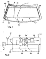
- an antenna glazing 1 is provided with a field of heating and antenna 2, which has been fabricated in known manner by screen printing a predetermined pattern of structure into an electrically conductive baking paste. Details of this structure known per se are not represented here; it will only be indicated that several narrow conductor tracks 2L extend transversely over the field of view of the glazing 1, between the two relatively wide lateral collector bars 2S, which are close to the edge of the glazing 1.
- the two collector bars 2S can be connected in a manner not shown in detail to an electric heating voltage, which circulates a current in the conductive tracks electrically connected in parallel with each other.
- HF high frequency signals
- a signal and power supply line 4 made in a known manner in coplanar bipolar form on the surface of the glazing unit 1 along its edge. extends to an appropriate interface 5 (multiple connector, flat conductor, plug-in connection) on the edge of the glazing 1.
- interface 5 multiple connector, flat conductor, plug-in connection
- connections are made to the receiving apparatus ( radio, tuner, TV, ...) as well as to a voltage source not shown.
- the supply voltage for the heating field itself can also be connected here.
- Such multipolar interfaces are in themselves part of the state of the art (see for example the document DE-PS 195 36 131 ) and will therefore not be discussed in detail here. No further attention will be given to shielding measures that may be necessary and the like, because these are commonplace for those skilled in the art.
- the antenna field 2, the electronic element HF 3 and the line 4 do not necessarily have to be all on the same surface of the glazing. It is also not necessary for the application of the invention to use a printed antenna structure.
- the line 4 to be protected can also be connected to a coating used as an antenna arranged inside a laminated glazing unit.
- the electronic element HF 3 can be incorporated in a composite, if its overall assembly is sufficiently flat.
- the line itself could of course also be incorporated in a composite, its electrical passivation is not mandatory, but it is still possible.
- a peripheral line in phantom lines indicates the inner edge line of an opaque colored frame 7, which usually surrounds as an outer limit the field of vision of the antenna glazing 1, which is otherwise transparent, and extends to outer edge thereof.
- a colored frame also masks the electronic elements of the antenna structures described here. It is recognized that, in the plane projection of the glazing, the busbars 2S, the electronic element HF 3, the coplanar line 4 and the interface 5 are located on this colored frame 7.
- Line 4 on the one hand, an HF (amplified) signal supplied by the electronic element HF 3 and, on the other hand, a supply voltage to the active electronic element HF 3 are supplied to a reception apparatus (not shown).
- Line 4 is composed in the present example asymmetrically of a wide conductive strip 4G and a narrow conductive strip 4S parallel to a constant distance therefrom. It is preferably printed during the same operation as the heating field and antenna 2 and is, in the mounted state of the glazing 1, exposed to the weather.
- the conductive strip 4G is closer to the edge of the glazing 1 than the band 4S, so that the latter respects a distance as large as possible of a metal body, in which the glazing 1 must be installed later.
- the 4G wide conductor strip can also, if necessary, be connected directly, for example by an electrically conductive adhesive, to the chassis of the vehicle.
- the conductive strips 4S, 4G and the heating field 2S, 2L it is possible, for example, to use a screen printing paste of the SP 1835 type of CERDEC with a silver content of 80%.
- the opaque colored frame 7 is printed with CERDEC black enamel 14252/80860. These two materials to be printed on one another are compatible with each other, and one can with them suitably respect the desired characteristic impedance of line 4.
- the Fig. 2 shows a possible discrete embodiment of the electronic element HF 3 and elements of the active corrosion protection.
- the connections of line 4 (4G, 4S) have been drawn, on the right side the connection 2A towards the antenna foot.
- the 4G connection serves as a ground, while the 4S connection leads both the RF signal level to a receiving device 8 (tuner) and a supply voltage superimposed on the RF signals. It goes without saying that the RF connection of the reception apparatus 8 is not sensitive to the presence of the supply voltage.
- the passivation voltage is an alternating voltage U P with an amplitude of 1.1 V and a frequency of 3000 ⁇ 100 Hz, which is produced by a voltage source 9 shown only schematically.
- This passivation voltage has been determined experimentally as being an optimum for active anti-corrosion protection of such lines respectively of such structures.
- This passivation voltage is therefore used in accordance with the invention for feeding the line 4 subject to corrosion, at the place where the operating voltage was usually applied in the active components HF.
- the voltage source 9 could also be integrated directly into the receiving apparatus 8, unlike the representation.
- the electronic element HF 3 comprises an antenna amplifier 3A, to which the antenna signals are transmitted immediately by 2A, and which is connected by a decoupling stage 3K to the line 4S.
- bandpass 38 When connected in parallel with the decoupling stage 3K, there is a bandpass 38 for filtering the supply voltage out of the HF signals, which sends the filtered voltage to a rectifier with a 3W AC / DC converter.
- the rectifier with converter must convert the rectified voltage to the operating voltage of the electronic components possibly integrated in a module. This voltage is then sent to the amplifier 3A, by a filtering / smoothing stage 3S or alternatively directly.
- the operating voltage U B and the ground can of course also be used for the power supply of other possible electronic elements, not shown here, for example still other amplifiers, etc.
Landscapes
- Chemical & Material Sciences (AREA)
- Engineering & Computer Science (AREA)
- Materials Engineering (AREA)
- Mechanical Engineering (AREA)
- Metallurgy (AREA)
- Organic Chemistry (AREA)
- Details Of Aerials (AREA)
- Support Of Aerials (AREA)
- Prevention Of Electric Corrosion (AREA)
- Input Circuits Of Receivers And Coupling Of Receivers And Audio Equipment (AREA)
- Joining Of Glass To Other Materials (AREA)
Claims (13)
- Korrosionsschutzsystem für eine mit einer Antenne versehene Verglasung (1) mit einer leitfähigen Struktur, die mindestens eine mehrpolige Leitung (4; 4S, 4G) umfasst, die von wenigstens zwei Strukturteilen gebildet wird, die auf der Oberfläche der Verglasung für die Übertragung von HF-Signalen von einem als HF-Signalteil bezeichneten Teil (4G) der Strukturteile sowie für den Anschluss eines HF-Elektronikelements (3, 3A) an eine Betriebsspannung (UB) parallel zueinander angeordnet sind, dadurch gekennzeichnet, dass das System eine Spannungsquelle (9) umfasst, um an den HF-Signal-Strukturteil und das HF-Elektronikelement (3, 3A) eine elektrische Passivierungsspannung (UP) die sich im Passivierungsbereich gegen Korrosion des Materials der Leitung befindet, anzulegen, und dass das System elektronische Anpassungselemente (3B, 3W, 3S), die mit dem HF-Elektronikelement verbunden sind, umfasst, um die Passivierungsspannung (UP) als Betriebsspannung (UB) des HF-Elektronikelements (3) zu nutzen.
- Korrosionsschutzsystem nach Anspruch 1, dadurch gekennzeichnet, dass die Spannungsquelle (9) für die Passivierungsspannung (UP) eine Wechsel- oder Gleichspannung in dem Bereich von 0,75 bis 1,8 V ist.
- Korrosionsschutzsystem nach Anspruch 1 oder 2, dadurch gekennzeichnet, dass die Spannungsquelle (9) in ein Gerät wie einen Tuner (8), an welches das elektronische HF-Elektronikelement in Betrieb angeschlossen ist, integriert ist.
- Korrosionsschutzsystem nach einem der Ansprüche 1, 2 oder 3, dadurch gekennzeichnet, dass die Passivierungsspannung (UP) eine Wechselspannung mit einer Frequenz von mehr als 2000 Hz und vorzugsweise zwischen 2000 und 4000 Hz ist.
- Korrosionsschutzsystem nach einem der Ansprüche 1 bis 4, dadurch gekennzeichnet, dass die Passivierungsspannung (UP) eine Wechselspannung von 1,1 V mit einer Frequenz von etwa 3000 Hz ist.
- Korrosionsschutzsystem nach einem der vorhergehenden Ansprüche, dadurch gekennzeichnet, dass, wenn die Betriebsspannung (UB) des HF-Elektronikelements (3, 3A) sich von der Passivierungsspannung (UP) unterscheidet, die elektronischen Anpassungselemente (3B, 3W, 3S) Mittel (3W) für die Umwandlung der Passivierungsspannung (UP) in die Betriebsspannung (UB) umfassen.
- Verfahren zur Verwendung einer mit einer Antenne versehenen Verglasung mit einer Antennenstruktur sowie mindestens einer mehrpoligen Leitung, die von Strukturteilen gebildet wird, die auf der Oberfläche der Verglasung für die Übertragung von HF-Signalen von einem als HF-Signalteil bezeichneten Teil der Strukturteile sowie für den Anschluss eines HF-Elektronikelements an eine Betriebsspannung parallel zueinander angeordnet sind, dadurch gekennzeichnet, dass an die Leitung und das an diese angeschlossene HF-Elektronikelement eine Passivierungsspannung die sich im Passivierungsbereich des Materials der Leitung befindet und sich den HF-Signalen überlagern läßt, angelegt wird, und dass diese Passivierungsspannung direkt oder nach Anpassung als Betriebsspannung des HF-Elektronikelements verwendet wird.
- Mit einer Antenne versehene Verglasung (1) für ein Fahrzeug, die ein HF-Elektronikelement (3) umfasst, das für eine festgelegte Betriebsspannung (UB) konstruiert ist und von einer mehrpoligen Leitung (4), die auf einer Fläche der Verglasung (1) angeordnet ist, mit elektrischem Strom versorgt werden kann, dadurch gekennzeichnet, dass sie das Schutzsystem nach einem der Ansprüche 1 bis 6 umfasst.
- Mit einer Antenne versehene Verglasung nach Anspruch 8, dadurch gekennzeichnet, dass, wenn die Passivierungsspannung (UP) eine Wechselspannung ist, sie einen Spannungsgleichrichter und -wandler (3W) umfasst, der mit dem HF-Elektronikelement (3) verbunden ist, wobei der Spannungsgleichrichter und -wandler diese gelieferte Wechselspannung in eine geeignete Gleichspannung umwandelt, um einen Verstärker (3A) des HF-Elektronikelements (3) zu versorgen.
- Mit einer Antenne versehene Verglasung nach Anspruch 8 oder 9, dadurch gekennzeichnet, dass das HF-Elektronikelement (3) auf einer Fläche der Verglasung (1) befestigt ist.
- Mit einer Antenne versehene Verglasung nach Anspruch 8 oder 9, dadurch gekennzeichnet, dass das HF-Elektronikelement (3) in eine Verbundglasscheibe eingebaut ist.
- Mit einer Antenne versehene Verglasung nach einem der Ansprüche 8 bis 11, dadurch gekennzeichnet, dass sich die mehrpolige Leitung (4) coplanar aus mindestens zwei leitfähigen Bändern (4G, 4S) zusammensetzt, die nebeneinander auf einer Fläche der Verglasung mit einem gleichbleibenden Abstand zueinander aufgebracht worden sind.
- Mit einer Antenne versehene Verglasung nach einem der Ansprüche 8 bis 11, dadurch gekennzeichnet, dass sich die mehrpolige Leitung (4) aus mindestens zwei leitfähigen Bändern (4G, 4S) zusammensetzt, die übereinander auf einer Fläche der Verglasung mit einem gleichbleibenden Abstand zueinander aufgebracht worden sind.
Priority Applications (1)
| Application Number | Priority Date | Filing Date | Title |
|---|---|---|---|
| PL04742619T PL1632007T3 (pl) | 2003-05-02 | 2004-04-30 | Układ ochrony antykorozyjnej dla oszklenia anteny i oszklenie anteny |
Applications Claiming Priority (2)
| Application Number | Priority Date | Filing Date | Title |
|---|---|---|---|
| DE10319607A DE10319607B3 (de) | 2003-05-02 | 2003-05-02 | Korrosionsschutzschaltung für eine Leiterstruktur auf einer Antennenscheibe, Verfahren zum Betreiben einer aktiven Antennenscheibe und Antennenscheibe für Fahrzeuge |
| PCT/FR2004/001055 WO2004100307A2 (fr) | 2003-05-02 | 2004-04-30 | Système de protection anti-corrosion pour vitrage d'antenne et vitrage d'antenne |
Publications (2)
| Publication Number | Publication Date |
|---|---|
| EP1632007A2 EP1632007A2 (de) | 2006-03-08 |
| EP1632007B1 true EP1632007B1 (de) | 2009-04-08 |
Family
ID=32981186
Family Applications (1)
| Application Number | Title | Priority Date | Filing Date |
|---|---|---|---|
| EP04742619A Expired - Lifetime EP1632007B1 (de) | 2003-05-02 | 2004-04-30 | Korrosionsschutzschaltung für eine scheibenantenne und scheibenantenne |
Country Status (9)
| Country | Link |
|---|---|
| EP (1) | EP1632007B1 (de) |
| JP (1) | JP4874091B2 (de) |
| KR (1) | KR101061935B1 (de) |
| CN (1) | CN1816939B (de) |
| AT (1) | ATE428195T1 (de) |
| DE (2) | DE10319607B3 (de) |
| ES (1) | ES2325024T3 (de) |
| PL (1) | PL1632007T3 (de) |
| WO (1) | WO2004100307A2 (de) |
Families Citing this family (3)
| Publication number | Priority date | Publication date | Assignee | Title |
|---|---|---|---|---|
| WO2013091961A1 (de) | 2011-12-20 | 2013-06-27 | Saint-Gobain Glass France | Verbundscheibe mit antennenstruktur und integrierter schaltfläche |
| JP5980437B2 (ja) * | 2012-10-11 | 2016-08-31 | エコスペック グローバル テクノロジー ピーティーイー エルティーディー. | 時間的に変化する電磁波を用いた、金属構造物の腐食予防をもたらすシステム及び方法 |
| CN103872465B (zh) * | 2014-04-18 | 2016-04-20 | 福耀玻璃工业集团股份有限公司 | 一种真有源玻璃天线及其制造方法 |
Family Cites Families (9)
| Publication number | Priority date | Publication date | Assignee | Title |
|---|---|---|---|---|
| US3692650A (en) * | 1970-08-24 | 1972-09-19 | Signal Oil & Gas Co | Cathodic protection system |
| AT384626B (de) * | 1985-07-12 | 1987-12-10 | D 3 Cathodic Products | Vorrichtung zur anwendung des kathodischen korrosionsschutzes an nicht erdverlegten anlagen |
| DE3911178A1 (de) * | 1989-04-06 | 1990-10-11 | Lindenmeier Heinz | Scheibenantennensystem mit antennenverstaerker |
| JPH07212118A (ja) * | 1994-01-18 | 1995-08-11 | Asahi Glass Co Ltd | ガラスアンテナのブースターアンプ |
| DE19536131C2 (de) * | 1995-09-28 | 2002-05-02 | Saint Gobain Sekurit D Gmbh | Diversity-Antennenscheibe für Fahrzeuge mit Anschlußelementen |
| JP2000101324A (ja) * | 1998-09-25 | 2000-04-07 | Sumitomo Constr Mach Co Ltd | 建設機械搭載用送受信機のアンテナ装置 |
| DE10002777C1 (de) * | 2000-01-22 | 2001-08-09 | Saint Gobain Sekurit D Gmbh | Kontaktierung einer Scheibe mit elektrischen Funktionen |
| US6441792B1 (en) * | 2001-07-13 | 2002-08-27 | Hrl Laboratories, Llc. | Low-profile, multi-antenna module, and method of integration into a vehicle |
| JP2004040144A (ja) * | 2002-06-28 | 2004-02-05 | Asahi Glass Co Ltd | 自動車用後部窓ガラスアンテナ |
-
2003
- 2003-05-02 DE DE10319607A patent/DE10319607B3/de not_active Withdrawn - After Issue
-
2004
- 2004-04-30 KR KR1020057020767A patent/KR101061935B1/ko not_active Expired - Fee Related
- 2004-04-30 PL PL04742619T patent/PL1632007T3/pl unknown
- 2004-04-30 CN CN2004800187510A patent/CN1816939B/zh not_active Expired - Fee Related
- 2004-04-30 JP JP2006505826A patent/JP4874091B2/ja not_active Expired - Fee Related
- 2004-04-30 DE DE602004020466T patent/DE602004020466D1/de not_active Expired - Lifetime
- 2004-04-30 ES ES04742619T patent/ES2325024T3/es not_active Expired - Lifetime
- 2004-04-30 AT AT04742619T patent/ATE428195T1/de not_active IP Right Cessation
- 2004-04-30 WO PCT/FR2004/001055 patent/WO2004100307A2/fr not_active Ceased
- 2004-04-30 EP EP04742619A patent/EP1632007B1/de not_active Expired - Lifetime
Also Published As
| Publication number | Publication date |
|---|---|
| WO2004100307A2 (fr) | 2004-11-18 |
| JP4874091B2 (ja) | 2012-02-08 |
| ATE428195T1 (de) | 2009-04-15 |
| KR20060008960A (ko) | 2006-01-27 |
| WO2004100307A8 (fr) | 2005-12-01 |
| PL1632007T3 (pl) | 2009-08-31 |
| CN1816939B (zh) | 2010-06-16 |
| DE10319607B3 (de) | 2004-10-14 |
| KR101061935B1 (ko) | 2011-09-02 |
| DE602004020466D1 (de) | 2009-05-20 |
| ES2325024T3 (es) | 2009-08-24 |
| CN1816939A (zh) | 2006-08-09 |
| EP1632007A2 (de) | 2006-03-08 |
| WO2004100307A3 (fr) | 2005-01-20 |
| JP2006525710A (ja) | 2006-11-09 |
Similar Documents
| Publication | Publication Date | Title |
|---|---|---|
| EP1399986B1 (de) | Scheibenantenne mit hochfrequenzelement | |
| US6320276B1 (en) | Window with an aerial for motor vehicles | |
| CA2879446C (en) | Composite pane with electrical contacting means | |
| KR101975690B1 (ko) | 전기 가열가능한 안테나 판유리 및 그를 제조하는 방법 | |
| JP6696502B2 (ja) | 車両用窓ガラス及びアンテナ | |
| US20150334779A1 (en) | Pane having an electric heating layer | |
| EP0766338B1 (de) | Multikontakt für Scheibenantenne | |
| CA2469708A1 (fr) | Vitre chauffante avec un revetement superficiel electriquement conducteur | |
| CN102934282B (zh) | 具有改善信噪比的天线配置和天线构造 | |
| US20110233182A1 (en) | Heated vehicle window | |
| EP1623480B1 (de) | Fensterscheibenantenne für kraftfahrzeuge | |
| FR2601194A1 (fr) | Antenne de glace de fenetre de vehicule utilisant un film conducteur transparent | |
| ES2773013T3 (es) | Panel con estructuras conductoras de electricidad | |
| EP1962133A3 (de) | Elektrochrome Vorrichtung ohne Positionsversatz zwischen den Substraten | |
| JPH09116322A (ja) | ガラスアンテナおよびコネクタ | |
| CN106463812A (zh) | 天线玻璃板 | |
| WO2014157535A1 (ja) | 車両用窓ガラス及びアンテナ | |
| EP1683234B1 (de) | Antennenanordnung und mit dieser antennenanordnung augestattetes fenster | |
| KR20100017369A (ko) | 플라스틱 글레이징에 대한 전기 터미널의 기계적 부착 | |
| US20170251527A1 (en) | Transparent pane with heated coating | |
| EP1632007B1 (de) | Korrosionsschutzschaltung für eine scheibenantenne und scheibenantenne | |
| US11001038B2 (en) | Laminated assembly | |
| FR2779889A1 (fr) | Detecteur de contact par effet capacitif | |
| US20230065516A1 (en) | Method for busbar hiding of a laminated glazing | |
| FR2877463A1 (fr) | Dispositif a module electronique indemontable |
Legal Events
| Date | Code | Title | Description |
|---|---|---|---|
| PUAI | Public reference made under article 153(3) epc to a published international application that has entered the european phase |
Free format text: ORIGINAL CODE: 0009012 |
|
| 17P | Request for examination filed |
Effective date: 20051202 |
|
| AK | Designated contracting states |
Kind code of ref document: A2 Designated state(s): AT BE BG CH CY CZ DE DK EE ES FI FR GB GR HU IE IT LI LU MC NL PL PT RO SE SI SK TR |
|
| DAX | Request for extension of the european patent (deleted) | ||
| GRAP | Despatch of communication of intention to grant a patent |
Free format text: ORIGINAL CODE: EPIDOSNIGR1 |
|
| GRAS | Grant fee paid |
Free format text: ORIGINAL CODE: EPIDOSNIGR3 |
|
| GRAA | (expected) grant |
Free format text: ORIGINAL CODE: 0009210 |
|
| AK | Designated contracting states |
Kind code of ref document: B1 Designated state(s): AT BE BG CH CY CZ DE DK EE ES FI FR GB GR HU IE IT LI LU MC NL PL PT RO SE SI SK TR |
|
| REG | Reference to a national code |
Ref country code: GB Ref legal event code: FG4D Free format text: NOT ENGLISH |
|
| REG | Reference to a national code |
Ref country code: CH Ref legal event code: EP |
|
| REG | Reference to a national code |
Ref country code: IE Ref legal event code: FG4D |
|
| REF | Corresponds to: |
Ref document number: 602004020466 Country of ref document: DE Date of ref document: 20090520 Kind code of ref document: P |
|
| PG25 | Lapsed in a contracting state [announced via postgrant information from national office to epo] |
Ref country code: SI Free format text: LAPSE BECAUSE OF FAILURE TO SUBMIT A TRANSLATION OF THE DESCRIPTION OR TO PAY THE FEE WITHIN THE PRESCRIBED TIME-LIMIT Effective date: 20090408 |
|
| REG | Reference to a national code |
Ref country code: ES Ref legal event code: FG2A Ref document number: 2325024 Country of ref document: ES Kind code of ref document: T3 |
|
| REG | Reference to a national code |
Ref country code: PL Ref legal event code: T3 |
|
| NLV1 | Nl: lapsed or annulled due to failure to fulfill the requirements of art. 29p and 29m of the patents act | ||
| REG | Reference to a national code |
Ref country code: IE Ref legal event code: FD4D |
|
| PG25 | Lapsed in a contracting state [announced via postgrant information from national office to epo] |
Ref country code: AT Free format text: LAPSE BECAUSE OF FAILURE TO SUBMIT A TRANSLATION OF THE DESCRIPTION OR TO PAY THE FEE WITHIN THE PRESCRIBED TIME-LIMIT Effective date: 20090408 Ref country code: PT Free format text: LAPSE BECAUSE OF FAILURE TO SUBMIT A TRANSLATION OF THE DESCRIPTION OR TO PAY THE FEE WITHIN THE PRESCRIBED TIME-LIMIT Effective date: 20090908 Ref country code: FI Free format text: LAPSE BECAUSE OF FAILURE TO SUBMIT A TRANSLATION OF THE DESCRIPTION OR TO PAY THE FEE WITHIN THE PRESCRIBED TIME-LIMIT Effective date: 20090408 |
|
| PG25 | Lapsed in a contracting state [announced via postgrant information from national office to epo] |
Ref country code: SE Free format text: LAPSE BECAUSE OF FAILURE TO SUBMIT A TRANSLATION OF THE DESCRIPTION OR TO PAY THE FEE WITHIN THE PRESCRIBED TIME-LIMIT Effective date: 20090708 Ref country code: NL Free format text: LAPSE BECAUSE OF FAILURE TO SUBMIT A TRANSLATION OF THE DESCRIPTION OR TO PAY THE FEE WITHIN THE PRESCRIBED TIME-LIMIT Effective date: 20090408 |
|
| REG | Reference to a national code |
Ref country code: CH Ref legal event code: PL |
|
| PG25 | Lapsed in a contracting state [announced via postgrant information from national office to epo] |
Ref country code: EE Free format text: LAPSE BECAUSE OF FAILURE TO SUBMIT A TRANSLATION OF THE DESCRIPTION OR TO PAY THE FEE WITHIN THE PRESCRIBED TIME-LIMIT Effective date: 20090408 Ref country code: CH Free format text: LAPSE BECAUSE OF NON-PAYMENT OF DUE FEES Effective date: 20090430 Ref country code: LI Free format text: LAPSE BECAUSE OF NON-PAYMENT OF DUE FEES Effective date: 20090430 Ref country code: IE Free format text: LAPSE BECAUSE OF FAILURE TO SUBMIT A TRANSLATION OF THE DESCRIPTION OR TO PAY THE FEE WITHIN THE PRESCRIBED TIME-LIMIT Effective date: 20090408 Ref country code: DK Free format text: LAPSE BECAUSE OF FAILURE TO SUBMIT A TRANSLATION OF THE DESCRIPTION OR TO PAY THE FEE WITHIN THE PRESCRIBED TIME-LIMIT Effective date: 20090408 Ref country code: RO Free format text: LAPSE BECAUSE OF FAILURE TO SUBMIT A TRANSLATION OF THE DESCRIPTION OR TO PAY THE FEE WITHIN THE PRESCRIBED TIME-LIMIT Effective date: 20090408 |
|
| PLBE | No opposition filed within time limit |
Free format text: ORIGINAL CODE: 0009261 |
|
| STAA | Information on the status of an ep patent application or granted ep patent |
Free format text: STATUS: NO OPPOSITION FILED WITHIN TIME LIMIT |
|
| PG25 | Lapsed in a contracting state [announced via postgrant information from national office to epo] |
Ref country code: SK Free format text: LAPSE BECAUSE OF FAILURE TO SUBMIT A TRANSLATION OF THE DESCRIPTION OR TO PAY THE FEE WITHIN THE PRESCRIBED TIME-LIMIT Effective date: 20090408 |
|
| 26N | No opposition filed |
Effective date: 20100111 |
|
| PG25 | Lapsed in a contracting state [announced via postgrant information from national office to epo] |
Ref country code: BG Free format text: LAPSE BECAUSE OF FAILURE TO SUBMIT A TRANSLATION OF THE DESCRIPTION OR TO PAY THE FEE WITHIN THE PRESCRIBED TIME-LIMIT Effective date: 20090708 |
|
| PG25 | Lapsed in a contracting state [announced via postgrant information from national office to epo] |
Ref country code: MC Free format text: LAPSE BECAUSE OF NON-PAYMENT OF DUE FEES Effective date: 20090430 |
|
| PG25 | Lapsed in a contracting state [announced via postgrant information from national office to epo] |
Ref country code: GR Free format text: LAPSE BECAUSE OF FAILURE TO SUBMIT A TRANSLATION OF THE DESCRIPTION OR TO PAY THE FEE WITHIN THE PRESCRIBED TIME-LIMIT Effective date: 20090709 |
|
| PG25 | Lapsed in a contracting state [announced via postgrant information from national office to epo] |
Ref country code: HU Free format text: LAPSE BECAUSE OF FAILURE TO SUBMIT A TRANSLATION OF THE DESCRIPTION OR TO PAY THE FEE WITHIN THE PRESCRIBED TIME-LIMIT Effective date: 20091009 |
|
| PG25 | Lapsed in a contracting state [announced via postgrant information from national office to epo] |
Ref country code: CY Free format text: LAPSE BECAUSE OF FAILURE TO SUBMIT A TRANSLATION OF THE DESCRIPTION OR TO PAY THE FEE WITHIN THE PRESCRIBED TIME-LIMIT Effective date: 20090408 |
|
| REG | Reference to a national code |
Ref country code: FR Ref legal event code: PLFP Year of fee payment: 13 |
|
| REG | Reference to a national code |
Ref country code: FR Ref legal event code: PLFP Year of fee payment: 14 |
|
| REG | Reference to a national code |
Ref country code: FR Ref legal event code: PLFP Year of fee payment: 15 |
|
| PGFP | Annual fee paid to national office [announced via postgrant information from national office to epo] |
Ref country code: GB Payment date: 20220310 Year of fee payment: 19 |
|
| PGFP | Annual fee paid to national office [announced via postgrant information from national office to epo] |
Ref country code: PL Payment date: 20220314 Year of fee payment: 19 Ref country code: IT Payment date: 20220310 Year of fee payment: 19 Ref country code: BE Payment date: 20220321 Year of fee payment: 19 |
|
| PGFP | Annual fee paid to national office [announced via postgrant information from national office to epo] |
Ref country code: LU Payment date: 20220421 Year of fee payment: 19 Ref country code: FR Payment date: 20220428 Year of fee payment: 19 Ref country code: ES Payment date: 20220506 Year of fee payment: 19 Ref country code: DE Payment date: 20220309 Year of fee payment: 19 Ref country code: CZ Payment date: 20220419 Year of fee payment: 19 |
|
| PGFP | Annual fee paid to national office [announced via postgrant information from national office to epo] |
Ref country code: TR Payment date: 20220427 Year of fee payment: 19 |
|
| REG | Reference to a national code |
Ref country code: DE Ref legal event code: R119 Ref document number: 602004020466 Country of ref document: DE |
|
| GBPC | Gb: european patent ceased through non-payment of renewal fee |
Effective date: 20230430 |
|
| PG25 | Lapsed in a contracting state [announced via postgrant information from national office to epo] |
Ref country code: LU Free format text: LAPSE BECAUSE OF NON-PAYMENT OF DUE FEES Effective date: 20230430 |
|
| REG | Reference to a national code |
Ref country code: BE Ref legal event code: MM Effective date: 20230430 |
|
| PG25 | Lapsed in a contracting state [announced via postgrant information from national office to epo] |
Ref country code: GB Free format text: LAPSE BECAUSE OF NON-PAYMENT OF DUE FEES Effective date: 20230430 |
|
| PG25 | Lapsed in a contracting state [announced via postgrant information from national office to epo] |
Ref country code: GB Free format text: LAPSE BECAUSE OF NON-PAYMENT OF DUE FEES Effective date: 20230430 Ref country code: FR Free format text: LAPSE BECAUSE OF NON-PAYMENT OF DUE FEES Effective date: 20230430 Ref country code: DE Free format text: LAPSE BECAUSE OF NON-PAYMENT OF DUE FEES Effective date: 20231103 Ref country code: CZ Free format text: LAPSE BECAUSE OF NON-PAYMENT OF DUE FEES Effective date: 20230430 |
|
| PG25 | Lapsed in a contracting state [announced via postgrant information from national office to epo] |
Ref country code: BE Free format text: LAPSE BECAUSE OF NON-PAYMENT OF DUE FEES Effective date: 20230430 |
|
| PG25 | Lapsed in a contracting state [announced via postgrant information from national office to epo] |
Ref country code: IT Free format text: LAPSE BECAUSE OF NON-PAYMENT OF DUE FEES Effective date: 20230430 |
|
| REG | Reference to a national code |
Ref country code: ES Ref legal event code: FD2A Effective date: 20240531 |
|
| PG25 | Lapsed in a contracting state [announced via postgrant information from national office to epo] |
Ref country code: ES Free format text: LAPSE BECAUSE OF NON-PAYMENT OF DUE FEES Effective date: 20230501 |
|
| PG25 | Lapsed in a contracting state [announced via postgrant information from national office to epo] |
Ref country code: ES Free format text: LAPSE BECAUSE OF NON-PAYMENT OF DUE FEES Effective date: 20230501 |
|
| PG25 | Lapsed in a contracting state [announced via postgrant information from national office to epo] |
Ref country code: PL Free format text: LAPSE BECAUSE OF NON-PAYMENT OF DUE FEES Effective date: 20230430 |
|
| PG25 | Lapsed in a contracting state [announced via postgrant information from national office to epo] |
Ref country code: PL Free format text: LAPSE BECAUSE OF NON-PAYMENT OF DUE FEES Effective date: 20230430 |