EP1632007B1 - Anticorrosive protection system for antenna glass, and corresponding antenna glass - Google Patents
Anticorrosive protection system for antenna glass, and corresponding antenna glass Download PDFInfo
- Publication number
- EP1632007B1 EP1632007B1 EP04742619A EP04742619A EP1632007B1 EP 1632007 B1 EP1632007 B1 EP 1632007B1 EP 04742619 A EP04742619 A EP 04742619A EP 04742619 A EP04742619 A EP 04742619A EP 1632007 B1 EP1632007 B1 EP 1632007B1
- Authority
- EP
- European Patent Office
- Prior art keywords
- voltage
- glazing
- electronic component
- antenna
- passivation
- Prior art date
- Legal status (The legal status is an assumption and is not a legal conclusion. Google has not performed a legal analysis and makes no representation as to the accuracy of the status listed.)
- Expired - Lifetime
Links
- 230000004224 protection Effects 0.000 title claims abstract description 15
- 239000011521 glass Substances 0.000 title description 8
- 238000002161 passivation Methods 0.000 claims abstract description 31
- 238000005260 corrosion Methods 0.000 claims abstract description 21
- 230000007797 corrosion Effects 0.000 claims abstract description 14
- 230000005405 multipole Effects 0.000 claims abstract description 10
- 238000000034 method Methods 0.000 claims abstract description 8
- 239000000463 material Substances 0.000 claims description 6
- 230000006978 adaptation Effects 0.000 claims 1
- 239000004020 conductor Substances 0.000 abstract description 11
- 238000009499 grossing Methods 0.000 abstract description 2
- 238000010438 heat treatment Methods 0.000 description 5
- 238000007650 screen-printing Methods 0.000 description 5
- 238000000576 coating method Methods 0.000 description 3
- 239000000758 substrate Substances 0.000 description 3
- BQCADISMDOOEFD-UHFFFAOYSA-N Silver Chemical compound [Ag] BQCADISMDOOEFD-UHFFFAOYSA-N 0.000 description 2
- 239000011248 coating agent Substances 0.000 description 2
- 239000002131 composite material Substances 0.000 description 2
- 230000000694 effects Effects 0.000 description 2
- 238000001914 filtration Methods 0.000 description 2
- 239000010410 layer Substances 0.000 description 2
- 229910052751 metal Inorganic materials 0.000 description 2
- 239000002184 metal Substances 0.000 description 2
- 239000004033 plastic Substances 0.000 description 2
- 229920003023 plastic Polymers 0.000 description 2
- 230000001681 protective effect Effects 0.000 description 2
- 150000003839 salts Chemical class 0.000 description 2
- 239000007921 spray Substances 0.000 description 2
- 239000000853 adhesive Substances 0.000 description 1
- 230000001070 adhesive effect Effects 0.000 description 1
- 239000012790 adhesive layer Substances 0.000 description 1
- 230000008878 coupling Effects 0.000 description 1
- 238000010168 coupling process Methods 0.000 description 1
- 238000005859 coupling reaction Methods 0.000 description 1
- 238000013016 damping Methods 0.000 description 1
- 210000003298 dental enamel Anatomy 0.000 description 1
- 238000000151 deposition Methods 0.000 description 1
- 239000003989 dielectric material Substances 0.000 description 1
- 238000005485 electric heating Methods 0.000 description 1
- 238000001125 extrusion Methods 0.000 description 1
- 238000010304 firing Methods 0.000 description 1
- 230000002401 inhibitory effect Effects 0.000 description 1
- 239000005340 laminated glass Substances 0.000 description 1
- 230000002093 peripheral effect Effects 0.000 description 1
- 239000004417 polycarbonate Substances 0.000 description 1
- 229920000515 polycarbonate Polymers 0.000 description 1
- 230000037452 priming Effects 0.000 description 1
- 238000007639 printing Methods 0.000 description 1
- 229910052709 silver Inorganic materials 0.000 description 1
- 239000004332 silver Substances 0.000 description 1
- 239000000126 substance Substances 0.000 description 1
- 229920002994 synthetic fiber Polymers 0.000 description 1
Images
Classifications
-
- H—ELECTRICITY
- H01—ELECTRIC ELEMENTS
- H01Q—ANTENNAS, i.e. RADIO AERIALS
- H01Q1/00—Details of, or arrangements associated with, antennas
- H01Q1/27—Adaptation for use in or on movable bodies
- H01Q1/32—Adaptation for use in or on road or rail vehicles
-
- H—ELECTRICITY
- H01—ELECTRIC ELEMENTS
- H01Q—ANTENNAS, i.e. RADIO AERIALS
- H01Q1/00—Details of, or arrangements associated with, antennas
- H01Q1/12—Supports; Mounting means
- H01Q1/1271—Supports; Mounting means for mounting on windscreens
-
- C—CHEMISTRY; METALLURGY
- C23—COATING METALLIC MATERIAL; COATING MATERIAL WITH METALLIC MATERIAL; CHEMICAL SURFACE TREATMENT; DIFFUSION TREATMENT OF METALLIC MATERIAL; COATING BY VACUUM EVAPORATION, BY SPUTTERING, BY ION IMPLANTATION OR BY CHEMICAL VAPOUR DEPOSITION, IN GENERAL; INHIBITING CORROSION OF METALLIC MATERIAL OR INCRUSTATION IN GENERAL
- C23F—NON-MECHANICAL REMOVAL OF METALLIC MATERIAL FROM SURFACE; INHIBITING CORROSION OF METALLIC MATERIAL OR INCRUSTATION IN GENERAL; MULTI-STEP PROCESSES FOR SURFACE TREATMENT OF METALLIC MATERIAL INVOLVING AT LEAST ONE PROCESS PROVIDED FOR IN CLASS C23 AND AT LEAST ONE PROCESS COVERED BY SUBCLASS C21D OR C22F OR CLASS C25
- C23F13/00—Inhibiting corrosion of metals by anodic or cathodic protection
- C23F13/005—Anodic protection
-
- C—CHEMISTRY; METALLURGY
- C23—COATING METALLIC MATERIAL; COATING MATERIAL WITH METALLIC MATERIAL; CHEMICAL SURFACE TREATMENT; DIFFUSION TREATMENT OF METALLIC MATERIAL; COATING BY VACUUM EVAPORATION, BY SPUTTERING, BY ION IMPLANTATION OR BY CHEMICAL VAPOUR DEPOSITION, IN GENERAL; INHIBITING CORROSION OF METALLIC MATERIAL OR INCRUSTATION IN GENERAL
- C23F—NON-MECHANICAL REMOVAL OF METALLIC MATERIAL FROM SURFACE; INHIBITING CORROSION OF METALLIC MATERIAL OR INCRUSTATION IN GENERAL; MULTI-STEP PROCESSES FOR SURFACE TREATMENT OF METALLIC MATERIAL INVOLVING AT LEAST ONE PROCESS PROVIDED FOR IN CLASS C23 AND AT LEAST ONE PROCESS COVERED BY SUBCLASS C21D OR C22F OR CLASS C25
- C23F13/00—Inhibiting corrosion of metals by anodic or cathodic protection
- C23F13/02—Inhibiting corrosion of metals by anodic or cathodic protection cathodic; Selection of conditions, parameters or procedures for cathodic protection, e.g. of electrical conditions
- C23F13/04—Controlling or regulating desired parameters
-
- H—ELECTRICITY
- H01—ELECTRIC ELEMENTS
- H01Q—ANTENNAS, i.e. RADIO AERIALS
- H01Q1/00—Details of, or arrangements associated with, antennas
- H01Q1/02—Arrangements for de-icing; Arrangements for drying-out ; Arrangements for cooling; Arrangements for preventing corrosion
-
- H—ELECTRICITY
- H01—ELECTRIC ELEMENTS
- H01Q—ANTENNAS, i.e. RADIO AERIALS
- H01Q1/00—Details of, or arrangements associated with, antennas
- H01Q1/12—Supports; Mounting means
Definitions
- the invention relates to an anti-corrosion protection system for antenna glazing with a surface conducting structure having the features of claim 1.
- Glass windows of vehicles, glass and / or plastic are very often provided with electrically conductive structures, for example to heat them and / or to form antenna structures.
- the surface structures are screen printed (thick film technique) from an electrically conductive silver paste, which is then consolidated by firing.
- Antenna lines or parts thereof are also often conducted on the surface of the transparent substrate; these can also be used for power supply (remote power supply, for example from a tuner) of high frequency electronic elements (HF), such as antenna amplifiers and the like, arranged directly on the glazed antenna.
- HF high frequency electronic elements
- the lines themselves must not radiate and have a characteristic impedance defined, constant over the length. This requirement can be met by two or more parallel coplanar conductors with constant spacing and constant width.
- Embodiments of such signal lines and active antennas are described in the document DE-A1-39 11 178 where, to form coplanar signal and power lines on an antenna glazing of dielectric material, the line itself is combined with one or two ground tracks laid in parallel.
- a major disadvantage of such printed lines leading the normal service voltage of vehicles is however manifested in operation, when exposed to the weather.
- the supply voltage for the amplifier (s) is applied as an offset DC voltage on one of the conductors.
- Amplifiers are associated with electronic elements to separate the offset DC voltage as the operating voltage of the RF signals.
- a potential difference of 12 V DC between the signal conductor and ground is applied in service.
- This difference in potential, applied to a coplanar line in the thick layer technique already leads in 5 minutes to first corrosion phenomena, by the salt spray test according to DIN 50021-SS. After 10 minutes, there is a massive corrosion of the conductive structure.
- Said salt spray test simulates the corrosive effects for the lifetime of the component in a greatly shortened period of time; its application to antenna structures placed on vehicle windows is however not prescribed until now.
- corrosion damage can, in principle, also occur in other printed structures, for example in the heating field and the antenna itself, even if they do not affect their operating mode as seriously.
- the problem underlying the invention is to provide effective protection against electrical corrosion for antenna glazings with a conductive structure with surface lines conducting the voltage.
- the invention proposes for this purpose an anti-corrosion protection system for an antenna glazing with a conductive structure, comprising the characteristics according to the independent claim 1.
- the invention can make it possible to dispense with an additional passive coating on the line.
- the multipole line which is conducted parallel to a ground rail is passivable by the choice of an amplitude and, where appropriate, an appropriate signal frequency.
- the value of the passivation voltage will be determined individually for the material of the line to be protected against corrosion. It is generally possible to determine a marked passivation range depending on the value of the external voltage or passivation, in which the corrosion current (proportional to the rate of disintegration of the metal) is minimized or even tends to zero, which means that no corrosion no longer occurs.
- a sufficient corrosion inhibiting effect (“active" range) is not obtained, whereas in the case of voltages that are too high (greater than the "priming potential"), a a state called “transpassive” appears, in which the protective effect no longer acts and the corrosion current again increases sharply.
- the electronic matching elements can be separated from the electronic element HF or even integrated in this element for its direct supply by the passivation voltage.
- Preferred voltage values for passivation of the materials usually used for such conductive structures have been determined in the range of 0.75 to 1.8 V DC or AC voltage.
- the voltage source is integrated into a device connected in service to the electronic element HF, such as a tuner.
- the passivation voltage according to the invention may be alternating and preferably be sinusoidal and be in the frequency range greater than 2000 Hz, preferably between 2000 and 4000 Hz or around 3000 Hz. A maximum of passivation has been determined. with 1.1 V and 3000 Hz ⁇ 100 Hz.
- the invention also proposes a method of using an active antenna glazing with an antenna structure as well as with at least one multipole line formed by structural parts arranged parallel to each other on the glazing surface for transmitting RF signals as well as for connecting an RF electronic element to an operating voltage comprising the characteristics according to independent claim 7.
- the invention also proposes a vehicle antenna glazing comprising an electronic element HF designed for a specific operating voltage and capable of being powered by a multipolar line (4) disposed on a surface of the glazing unit, according to claim 8 comprising the system protection device according to one of claims 1 to 6.
- the glazing may comprise a rectifier and voltage converter which is associated with the electronic element HF, said rectifier and voltage converter converting said supplied AC voltage into a DC voltage suitable for supplying an amplifier of electronic element HF.
- the electronic element HF can be fixed on a surface of the glazing.
- the electronic element HF can be inserted into a laminated glazing unit.
- the multipolar line may be composed coplanar of at least two conductive tracks deposited next to each other on a surface of the glazing, at a constant distance from one another.
- the multipole line may also consist of at least two conductive tracks deposited one above the other on a surface of the glazing, at a constant distance from one another.
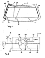
- an antenna glazing 1 is provided with a field of heating and antenna 2, which has been fabricated in known manner by screen printing a predetermined pattern of structure into an electrically conductive baking paste. Details of this structure known per se are not represented here; it will only be indicated that several narrow conductor tracks 2L extend transversely over the field of view of the glazing 1, between the two relatively wide lateral collector bars 2S, which are close to the edge of the glazing 1.
- the two collector bars 2S can be connected in a manner not shown in detail to an electric heating voltage, which circulates a current in the conductive tracks electrically connected in parallel with each other.
- HF high frequency signals
- a signal and power supply line 4 made in a known manner in coplanar bipolar form on the surface of the glazing unit 1 along its edge. extends to an appropriate interface 5 (multiple connector, flat conductor, plug-in connection) on the edge of the glazing 1.
- interface 5 multiple connector, flat conductor, plug-in connection
- connections are made to the receiving apparatus ( radio, tuner, TV, ...) as well as to a voltage source not shown.
- the supply voltage for the heating field itself can also be connected here.
- Such multipolar interfaces are in themselves part of the state of the art (see for example the document DE-PS 195 36 131 ) and will therefore not be discussed in detail here. No further attention will be given to shielding measures that may be necessary and the like, because these are commonplace for those skilled in the art.
- the antenna field 2, the electronic element HF 3 and the line 4 do not necessarily have to be all on the same surface of the glazing. It is also not necessary for the application of the invention to use a printed antenna structure.
- the line 4 to be protected can also be connected to a coating used as an antenna arranged inside a laminated glazing unit.
- the electronic element HF 3 can be incorporated in a composite, if its overall assembly is sufficiently flat.
- the line itself could of course also be incorporated in a composite, its electrical passivation is not mandatory, but it is still possible.
- a peripheral line in phantom lines indicates the inner edge line of an opaque colored frame 7, which usually surrounds as an outer limit the field of vision of the antenna glazing 1, which is otherwise transparent, and extends to outer edge thereof.
- a colored frame also masks the electronic elements of the antenna structures described here. It is recognized that, in the plane projection of the glazing, the busbars 2S, the electronic element HF 3, the coplanar line 4 and the interface 5 are located on this colored frame 7.
- Line 4 on the one hand, an HF (amplified) signal supplied by the electronic element HF 3 and, on the other hand, a supply voltage to the active electronic element HF 3 are supplied to a reception apparatus (not shown).
- Line 4 is composed in the present example asymmetrically of a wide conductive strip 4G and a narrow conductive strip 4S parallel to a constant distance therefrom. It is preferably printed during the same operation as the heating field and antenna 2 and is, in the mounted state of the glazing 1, exposed to the weather.
- the conductive strip 4G is closer to the edge of the glazing 1 than the band 4S, so that the latter respects a distance as large as possible of a metal body, in which the glazing 1 must be installed later.
- the 4G wide conductor strip can also, if necessary, be connected directly, for example by an electrically conductive adhesive, to the chassis of the vehicle.
- the conductive strips 4S, 4G and the heating field 2S, 2L it is possible, for example, to use a screen printing paste of the SP 1835 type of CERDEC with a silver content of 80%.
- the opaque colored frame 7 is printed with CERDEC black enamel 14252/80860. These two materials to be printed on one another are compatible with each other, and one can with them suitably respect the desired characteristic impedance of line 4.
- the Fig. 2 shows a possible discrete embodiment of the electronic element HF 3 and elements of the active corrosion protection.
- the connections of line 4 (4G, 4S) have been drawn, on the right side the connection 2A towards the antenna foot.
- the 4G connection serves as a ground, while the 4S connection leads both the RF signal level to a receiving device 8 (tuner) and a supply voltage superimposed on the RF signals. It goes without saying that the RF connection of the reception apparatus 8 is not sensitive to the presence of the supply voltage.
- the passivation voltage is an alternating voltage U P with an amplitude of 1.1 V and a frequency of 3000 ⁇ 100 Hz, which is produced by a voltage source 9 shown only schematically.
- This passivation voltage has been determined experimentally as being an optimum for active anti-corrosion protection of such lines respectively of such structures.
- This passivation voltage is therefore used in accordance with the invention for feeding the line 4 subject to corrosion, at the place where the operating voltage was usually applied in the active components HF.
- the voltage source 9 could also be integrated directly into the receiving apparatus 8, unlike the representation.
- the electronic element HF 3 comprises an antenna amplifier 3A, to which the antenna signals are transmitted immediately by 2A, and which is connected by a decoupling stage 3K to the line 4S.
- bandpass 38 When connected in parallel with the decoupling stage 3K, there is a bandpass 38 for filtering the supply voltage out of the HF signals, which sends the filtered voltage to a rectifier with a 3W AC / DC converter.
- the rectifier with converter must convert the rectified voltage to the operating voltage of the electronic components possibly integrated in a module. This voltage is then sent to the amplifier 3A, by a filtering / smoothing stage 3S or alternatively directly.
- the operating voltage U B and the ground can of course also be used for the power supply of other possible electronic elements, not shown here, for example still other amplifiers, etc.
Landscapes
- Chemical & Material Sciences (AREA)
- Engineering & Computer Science (AREA)
- Materials Engineering (AREA)
- Mechanical Engineering (AREA)
- Metallurgy (AREA)
- Organic Chemistry (AREA)
- Details Of Aerials (AREA)
- Support Of Aerials (AREA)
- Input Circuits Of Receivers And Coupling Of Receivers And Audio Equipment (AREA)
- Prevention Of Electric Corrosion (AREA)
- Joining Of Glass To Other Materials (AREA)
Abstract
Description
L'invention se rapporte à un système de protection anti-corrosion pour vitrage d'antenne avec une structure conductrice de surface ayant les caractéristiques de la revendication 1.The invention relates to an anti-corrosion protection system for antenna glazing with a surface conducting structure having the features of
Les vitrages de fenêtres de véhicules, en verre et/ou en matière plastique, sont très souvent pourvus de structures électriquement conductrices, par exemple pour les chauffer et/ou pour y former des structures d'antenne. La plupart du temps, les structures de surface sont imprimées par sérigraphie (technique à couche épaisse) à partir d'une pâte d'argent électriquement conductrice, qui est ensuite consolidée par cuisson.Glass windows of vehicles, glass and / or plastic, are very often provided with electrically conductive structures, for example to heat them and / or to form antenna structures. Most of the time, the surface structures are screen printed (thick film technique) from an electrically conductive silver paste, which is then consolidated by firing.
Les lignes d'arrivée d'antenne ou des parties de celles-ci sont également souvent menées sur la surface du substrat transparent; celles-ci peuvent également servir pour l'alimentation en courant (alimentation à distance, par exemple à partir d'un tuner) d'éléments électroniques à haute fréquence (HF), comme des amplificateurs d'antenne et analogues, disposés directement sur le vitrage d'antenne. On peut ainsi former au total une antenne active. Les lignes elles-mêmes ne doivent pas rayonner et possèdent une impédance caractéristique définie, constante sur la longueur. Cette exigence peut être rencontrée par deux ou plus de deux conducteurs coplanaires parallèles avec un écartement constant et avec une largeur constante.Antenna lines or parts thereof are also often conducted on the surface of the transparent substrate; these can also be used for power supply (remote power supply, for example from a tuner) of high frequency electronic elements (HF), such as antenna amplifiers and the like, arranged directly on the glazed antenna. In this way, an active antenna can be formed in total. The lines themselves must not radiate and have a characteristic impedance defined, constant over the length. This requirement can be met by two or more parallel coplanar conductors with constant spacing and constant width.
Des formes de réalisation de telles lignes de signaux et d'antennes actives sont décrites dans le document
Un inconvénient majeur de telles lignes imprimées conduisant la tension de service normale de véhicules (environ 12 V =) se manifeste pourtant en fonctionnement, lorsqu'elles sont exposées aux intempéries. La tension d'alimentation pour le ou les amplificateurs est appliquée comme tension continue offset sur un des conducteurs. À l'amplificateur sont associés des éléments électroniques pour séparer la tension continue offset comme tension de service des signaux HF. À la ligne de signaux est alors appliquée en service une différence de potentiel de 12 VCC entre le conducteur de signaux et la masse. Cette différence de potentiel, appliquée à une ligne coplanaire dans la technique en couche épaisse, conduit déjà en 5 minutes à de premiers phénomènes de corrosion, par l'essai au brouillard salin selon la norme DIN 50021-SS. Après 10 minutes, il se produit une corrosion massive de la structure conductrice. Ledit essai au brouillard salin simule les effets corrosifs pour toute la durée de vie du composant en un laps de temps fortement raccourci ; son application à des structures d'antenne placées sur des vitrages de véhicules n'est pourtant pas prescrite jusqu'à présent.A major disadvantage of such printed lines leading the normal service voltage of vehicles (about 12 V =) is however manifested in operation, when exposed to the weather. The supply voltage for the amplifier (s) is applied as an offset DC voltage on one of the conductors. Amplifiers are associated with electronic elements to separate the offset DC voltage as the operating voltage of the RF signals. At the signal line, a potential difference of 12 V DC between the signal conductor and ground is applied in service. This difference in potential, applied to a coplanar line in the thick layer technique, already leads in 5 minutes to first corrosion phenomena, by the salt spray test according to DIN 50021-SS. After 10 minutes, there is a massive corrosion of the conductive structure. Said salt spray test simulates the corrosive effects for the lifetime of the component in a greatly shortened period of time; its application to antenna structures placed on vehicle windows is however not prescribed until now.
Les dégâts de corrosion qui apparaissent dégradent gravement les propriétés des lignes coplanaires, notamment par la diminution de la conductibilité à haute fréquence et par l'augmentation de l'amortissement de la ligne et ensuite le dérèglement de l'accord du système jusqu'à sa panne totale. Ces dégâts surviennent également lorsque les structures imprimées se trouvent sur une surface intérieure d'un vitrage de fenêtre à l'état monté. Le document précité n'examine pas ce problème.The corrosion damage that appears severely degrades the properties of the coplanar lines, in particular by reducing the high-frequency conductivity and by increasing the damping of the line, and then the disruption of the tuning of the system to its total failure. This damage also occurs when the printed structures are on an inner surface of a window pane in the mounted state. The above document does not discuss this problem.
Il est certes possible, avec certains frais, de protéger les lignes contre des attaques corrosives par des revêtements, des coiffes ou analogues. Cependant les coûts de ces protections ont empêché jusqu'à présent leur exploitation industrielle.It is certainly possible, with certain costs, to protect the lines against corrosive attacks by coatings, caps or the like. However, the costs of these protections have hitherto prevented their industrial exploitation.
Il faut souligner que des dégâts de corrosion peuvent en principe survenir également à d'autres structures imprimées, par exemple au champ de chauffage et d'antenne lui-même, même s'ils n'affectent cependant pas aussi gravement leur mode de fonctionnement.It should be emphasized that corrosion damage can, in principle, also occur in other printed structures, for example in the heating field and the antenna itself, even if they do not affect their operating mode as seriously.
Le problème à la base de l'invention est de procurer une protection efficace contre la corrosion électrique pour des vitrages d'antenne avec une structure conductrice avec des lignes de surface conduisant la tension.The problem underlying the invention is to provide effective protection against electrical corrosion for antenna glazings with a conductive structure with surface lines conducting the voltage.
Il conviendra également de décrire un procédé pour l'utilisation d'un tel vitrage d'antenne ainsi qu'un vitrage d'antenne équipé en conséquence.It will also be necessary to describe a method for the use of such an antenna glazing as well as an antenna glazing equipped accordingly.
L'invention propose à cet effet un système de protection anti-corrosion pour un vitrage d'antenne avec une structure conductrice, comprenant les caractéristiques selon la revendication indépendante 1.The invention proposes for this purpose an anti-corrosion protection system for an antenna glazing with a conductive structure, comprising the characteristics according to the
L'invention peut permettre de se passer d'un revêtement passivant supplémentaire sur la ligne.The invention can make it possible to dispense with an additional passive coating on the line.
Pour une passivation électrique et ainsi la protection anti-corrosion active, il faut entre deux conducteurs électriques non reliés entre eux par voie galvanique très proches l'un de l'autre sur une surface du substrat lui-même ou d'une autre manière, une différence de potentiel du niveau de la tension de passivation. Ceci peut être réalisé de façon particulièrement simple pour un vitrage d'antenne couplé de façon capacitive, qui est ainsi passivable dans un agencement spatial approprié en un pôle opposé.For electrical passivation and thus the active anti-corrosion protection, it is necessary between two electrical conductors not electrically connected to each other very close to one another on a surface of the substrate itself or in another way, a potential difference of the level of the passivation voltage. This can be done in a particularly simple manner for a capacitively coupled antenna glazing, which is thus passivable in a suitable spatial arrangement at an opposite pole.
Par exemple, la ligne multipolaire qui est menée parallèlement à un rail de masse (masse ou +12V), est passivable par le choix d'une amplitude et, le cas échéant, d'une fréquence de signal appropriées.For example, the multipole line which is conducted parallel to a ground rail (ground or + 12V), is passivable by the choice of an amplitude and, where appropriate, an appropriate signal frequency.
La valeur de la tension de passivation va être déterminée individuellement pour la matière de la ligne à protéger contre la corrosion. Il est en règle générale possible de déterminer une plage de passivation marquée en fonction de la valeur de la tension externe ou de passivation, dans laquelle le courant de corrosion (proportionnel à la vitesse de désagrégation du métal) est réduit au minimum, voire tend vers zéro, ce qui signifie qu'aucune corrosion n'a plus lieu. Dans le cas de tensions externes trop faibles, il n'est pas obtenu d'effet inhibiteur de corrosion suffisant (plage « active »), alors que dans le cas de tensions trop élevées (supérieures au « potentiel d'amorçage »), un état appelé « transpassif » apparaît, dans lequel l'effet de protection n'agit plus et le courant de corrosion augmente de nouveau nettement.The value of the passivation voltage will be determined individually for the material of the line to be protected against corrosion. It is generally possible to determine a marked passivation range depending on the value of the external voltage or passivation, in which the corrosion current (proportional to the rate of disintegration of the metal) is minimized or even tends to zero, which means that no corrosion no longer occurs. In the case of external voltages that are too low, a sufficient corrosion inhibiting effect ("active" range) is not obtained, whereas in the case of voltages that are too high (greater than the "priming potential"), a a state called "transpassive" appears, in which the protective effect no longer acts and the corrosion current again increases sharply.
Les éléments d'électroniques d'adaptation peuvent être séparés de l'élément électronique HF ou même intégrés dans cet élément pour son alimentation directe par la tension de passivation.The electronic matching elements can be separated from the electronic element HF or even integrated in this element for its direct supply by the passivation voltage.
Des valeurs de tension préférées pour la passivation des matériaux usuellement utilisés pour de telles structures conductrices ont été déterminées dans la plage de 0,75 à 1,8 V en tension continue ou alternative.Preferred voltage values for passivation of the materials usually used for such conductive structures have been determined in the range of 0.75 to 1.8 V DC or AC voltage.
La source de tension est intégrée dans un appareil raccordé en service à l'élément électronique HF, comme un tuner.The voltage source is integrated into a device connected in service to the electronic element HF, such as a tuner.
La tension de passivation selon l'invention peut être alternative et de préférence être sinusoïdale et se situer dans la gamme de fréquences supérieure à 2000 Hz, de préférence entre 2000 et 4000 Hz ou aux environs de 3000 Hz. Un maximum de passivation a été déterminé avec 1,1 V et 3000 Hz ± 100 Hz.The passivation voltage according to the invention may be alternating and preferably be sinusoidal and be in the frequency range greater than 2000 Hz, preferably between 2000 and 4000 Hz or around 3000 Hz. A maximum of passivation has been determined. with 1.1 V and 3000 Hz ± 100 Hz.
La possibilité d'une passivation électrique par application d'une tension électrique (alternative) relativement basse donne la possibilité de mettre en oeuvre de manière économique les structures conductrices à teneur en argent réalisées par exemple par sérigraphie.The possibility of electrical passivation by application of a relatively low (alternative) electrical voltage gives the possibility of economically implementing the silver-content conductive structures produced for example by screen printing.
L'effet de protection par application d'une tension électrique ne consomme que très peu d'énergie, ce qui n'occasionne que des frais de fonctionnement supplémentaires négligeables. Avec des densités de courant mesurées < 10 µA/cm2, des courants de repos apparaissent dans le mode de passivation, qui sont inférieurs de plusieurs ordres de grandeur aux valeurs de 1,5 mA admissibles dans le secteur automobile.The protective effect by applying a voltage consumes very little energy, which causes only negligible additional operating costs. With current densities measured <10 μA / cm 2 , quiescent currents appear in the passivation mode, which are several orders of magnitude lower than the 1.5 mA values acceptable in the automotive sector.
Il est le cas échéant possible de se passer de la cuisson de structures imprimées, ce qui est censé, en règle générale, augmenter leur résistance mécanique et chimique. Ceci simplifie également la mise en oeuvre d'autres substrats que le verre, par exemple des vitrages en matière synthétique.If necessary, it is possible to dispense with the baking of printed structures, which is supposed to increase their mechanical and chemical resistance as a rule. This also simplifies the use of other substrates than glass, for example glazing made of synthetic material.
Pour l'utilisation de l'invention, on n'envisage bien entendu pas uniquement des lignes disposées de façon coplanaire, donc avec deux ou plusieurs cordons disposés l'un à côté de l'autre sur la surface du vitrage. Avec les procédés modernes de sérigraphie, on peut aussi par exemple imprimer l'une sur l'autre plusieurs couches conductrices isolées l'une par rapport à l'autre. La protection anti-corrosion conforme à l'invention peut également être appliquée sans difficultés à de telles structures sandwich multipolaires ainsi qu'à des structures qui ne sont pas déposées par sérigraphie (mais par exemple par extrusion ou par d'autres procédés de dépôt de matériaux conducteurs).For the use of the invention, it is of course not envisaged not only lines arranged coplanar manner, so with two or more cords arranged one beside the other on the surface of the glazing. With modern screen printing processes, it is also possible for example to print one on the other several insulating layers insulated relative to each other. The anti-corrosion protection according to the invention can also be applied without difficulty to such multipole sandwich structures as well as to structures which are not deposited by screen printing (but for example by extrusion or by other methods of depositing conductive materials).
S'il est prévu sur un vitrage d'antenne plusieurs lignes du type dont il est question ici, on alimentera naturellement selon les possibilités leur totalité avec la tension de passivation (protection).If it is provided on an antenna glazing several lines of the type which is in question here, one will naturally feed according to the possibilities their totality with the voltage of passivation (protection).
L'invention propose également un procédé d'utilisation d'un vitrage d'antenne actif avec une structure d'antenne ainsi qu'avec au moins une ligne multipolaire formée par des parties de structure disposées parallèlement l'une à l'autre sur la surface du vitrage pour la transmission de signaux HF ainsi que pour le raccordement d'un élément électronique HF à une tension de service comprenant les caractéristiques selon la revendication indépendante 7.The invention also proposes a method of using an active antenna glazing with an antenna structure as well as with at least one multipole line formed by structural parts arranged parallel to each other on the glazing surface for transmitting RF signals as well as for connecting an RF electronic element to an operating voltage comprising the characteristics according to
L'invention propose aussi un vitrage d'antenne pour véhicule comprenant un élément électronique HF conçu pour une tension de service déterminée et susceptible d'être alimenté par une ligne multipolaire (4) disposée sur une surface du vitrage, selon revendication 8 comprenant le système de protection selon l'une des revendications 1 à 6.The invention also proposes a vehicle antenna glazing comprising an electronic element HF designed for a specific operating voltage and capable of being powered by a multipolar line (4) disposed on a surface of the glazing unit, according to claim 8 comprising the system protection device according to one of
Lorsque la tension de passivation est alternative, le vitrage peut comprendre un redresseur et convertisseur de tension qui est associé à l'élément électronique HF, ledit redresseur et convertisseur de tension convertissant ladite tension alternative fournie en une tension continue appropriée pour alimenter un amplificateur de l'élément électronique HF.When the passivation voltage is an alternative, the glazing may comprise a rectifier and voltage converter which is associated with the electronic element HF, said rectifier and voltage converter converting said supplied AC voltage into a DC voltage suitable for supplying an amplifier of electronic element HF.
L'élément électronique HF peut être fixé sur une surface du vitrage.The electronic element HF can be fixed on a surface of the glazing.
L'élément électronique HF peut être inséré dans un vitrage feuilleté.The electronic element HF can be inserted into a laminated glazing unit.
La ligne multipolaire peut se composer de façon coplanaire d'au moins deux pistes conductrices déposées l'une à côté de l'autre sur une surface du vitrage, à distance constante l'une de l'autre.The multipolar line may be composed coplanar of at least two conductive tracks deposited next to each other on a surface of the glazing, at a constant distance from one another.
La ligne multipolaire peut aussi se composer d'au moins deux pistes conductrices déposées l'une au-dessus de l'autre sur une surface du vitrage, à distance constante l'une de l'autre.The multipole line may also consist of at least two conductive tracks deposited one above the other on a surface of the glazing, at a constant distance from one another.
D'autres détails et avantages de l'objet de l'invention apparaîtront par les dessins d'un exemple de réalisation et par sa description détaillée qui suit.Other details and advantages of the subject of the invention will become apparent from the drawings of an exemplary embodiment and from its detailed description which follows.
Dans ces dessins, qui sont des représentations schématiques :
- la
Fig. 1 est une vue d'ensemble d'un vitrage d'antenne avec une structure d'antenne et une ligne coplanaire de signaux et d'alimentation réalisée sur la surface du vitrage; - la
Fig. 2 montre une vue de détail du montage d'un élément électronique HF et des éléments de la protection anti-corrosion.
- the
Fig. 1 is an overview of an antenna glazing with an antenna structure and a coplanar signal and power line made on the surface of the glazing; - the
Fig. 2 shows a detailed view of the mounting of an electronic element HF and the elements of the anti-corrosion protection.
Selon la
Avec un conducteur de couplage 2A (pied d'antenne) placé transversalement par rapport aux dites pistes conductrices 2L, des signaux à haute fréquence (HF) reçus par le champ d'antenne 2 (par exemple des signaux radio ou des signaux TV) sont transmis à un élément électronique HF 3, dont le montage sera encore expliqué plus en détail en relation avec la
Partant de l'élément électronique HF 3 disposé de façon connue en soi directement sur la surface du vitrage 1, une ligne de signaux et d'alimentation 4 réalisée de façon connue sous forme coplanaire bipolaire sur la surface du vitrage 1 le long de son bord s'étend jusqu'à une interface appropriée 5 (connecteur multiple, conducteur plat, jonction par fiche) sur le bord du vitrage 1. Ici, à l'état monté du vitrage 1, sont réalisés des raccordements vers l'appareil de réception (radio, tuner, TV,...) ainsi que vers une source de tension non représentée.Starting from the
On peut aussi raccorder ici la tension d'alimentation pour le champ de chauffage lui-même. De telles interfaces multipolaires font en soi partie de l'état de la technique (voir par exemple le document
Il faut remarquer que le champ d'antenne 2, l'élément électronique HF 3 et la ligne 4 ne doivent pas nécessairement se trouver tous sur la même surface du vitrage. Il n'est également pas nécessaire pour l'application de l'invention d'utiliser une structure d'antenne imprimée. Par exemple, la ligne 4 à protéger peut aussi être raccordée à un revêtement utilisé comme antenne disposé à l'intérieur d'un vitrage feuilleté. De même, l'élément électronique HF 3 peut être incorporé dans un composite, si son montage global est suffisamment plat.It should be noted that the
En principe, la ligne elle-même pourrait naturellement aussi être incorporée dans un composite, sa passivation électrique n'étant cependant pas obligatoire, elle reste néanmoins également possible.In principle, the line itself could of course also be incorporated in a composite, its electrical passivation is not mandatory, but it is still possible.
Une ligne périphérique en traits mixtes indique la ligne de bord intérieure d'un cadre coloré opaque 7, qui entoure de façon usuelle comme limite extérieure le champ de vision de la vitrage d'antenne 1 par ailleurs transparente et qui s'étend jusqu'au bord extérieur de celle-ci. Un tel cadre coloré masque aussi à la vue des éléments électronique des structures d'antenne décrites ici. On reconnaît que, dans la projection en plan du vitrage, les barres collectrices 2S, l'élément électronique HF 3, la ligne coplanaire 4 et l'interface 5 sont situés sur ce cadre coloré 7.A peripheral line in phantom lines indicates the inner edge line of an opaque
Par la ligne 4, on fournit d'une part à un appareil de réception non représenté des signaux HF (amplifiés) fournis par l'élément électronique HF 3 et d'autre part à l'élément électronique HF 3 actif une tension d'alimentation. La ligne 4 se compose dans le présent exemple de réalisation de manière asymétrique d'une bande conductrice large 4G et d'une bande conductrice étroite 4S parallèle à distance constante de celle-ci. Elle est de préférence imprimée au cours de la même opération que le champ de chauffage et d'antenne 2 et est, à l'état monté du vitrage 1, exposée aux intempéries. La bande conductrice 4G est plus proche du bord du vitrage 1 que la bande 4S, de telle façon que cette dernière respecte une distance aussi grande que possible d'une carrosserie métallique, dans laquelle le vitrage 1 doit être installé ultérieurement. La bande conductrice large 4G peut aussi, au besoin, être raccordée directement, par exemple par une colle électriquement conductrice, au châssis du véhicule.By line 4, on the one hand, an HF (amplified) signal supplied by the
Pour la configuration asymétrique représentée, il en résulte les dimensions suivantes :
- Impédance caractéristique ZL : 50 ohm
- Largeur de la ligne de signaux 4S : 0,8 mm
- Largeur de la fente : 4,1 mm
- Largeur de la bande de masse 4G : 5,7 mm
- Épaisseur de la vitre (diélectrique) : 3,85 mm
- Characteristic impedance ZL: 50 ohm
- Width of the 4S signal line: 0.8 mm
- Width of the slot: 4.1 mm
- Width of the 4G mass band: 5.7 mm
- Glass thickness (dielectric): 3.85 mm
Pour les bandes conductrices 4S, 4G et le champ de chauffage 2S, 2L, on peut par exemple employer une pâte de sérigraphie du type SP 1835 de CERDEC avec une teneur en argent de 80%. Le cadre coloré opaque 7 est imprimé avec un émail noir 14252/80860 de CERDEC. Ces deux matériaux à imprimer l'un sur l'autre sont compatibles l'un avec l'autre, et on peut avec ceux-ci respecter convenablement l'impédance caractéristique désirée de la ligne 4.For the
Si la ligne est déposée sur des surfaces de verres feuilletés avec un diélectrique mixte (verre/couche adhésive/verre) et/ou sur des vitres avec d'autres épaisseurs ou d'autres matériaux (matière plastique, par exemple du polycarbonate), leurs dimensions géométriques et le cas échéant les pâtes d'impression devront être adaptées de façon appropriée, de même si la ligne doit être conçue pour ZL = 75 ohm.If the line is deposited on laminated glass surfaces with a mixed dielectric (glass / adhesive layer / glass) and / or on panes with other thicknesses or other materials (plastics, eg polycarbonate), their geometrical dimensions and, where appropriate, the printing pastes should be suitably adapted, as should the line be designed for Z L = 75 ohm.
La
Il va de soi qu'un tel élément électronique HF peut également être conçu et utilisé sous une forme intégrée. En général, un montage aussi plat que possible est intéressant, qui est peu saillant au-dessus de la surface du vitrage ou qui peut aussi être utilisé incorporé dans un vitrage feuilleté.It goes without saying that such an electronic element HF can also be designed and used in an integrated form. In general, an assembly as flat as possible is interesting, which is little salient above the surface of the glazing or which can also be used incorporated in a laminated glazing.
Dans l'exemple de réalisation représenté, la tension de passivation est une tension alternative UP avec une amplitude de 1,1 V et une fréquence de 3000 ± 100 Hz, qui est produite par une source de tension 9 représentée seulement de façon schématique.In the exemplary embodiment shown, the passivation voltage is an alternating voltage U P with an amplitude of 1.1 V and a frequency of 3000 ± 100 Hz, which is produced by a voltage source 9 shown only schematically.
Cette tension de passivation a été déterminée par voie expérimentale comme étant un optimum pour une protection anti-corrosion active de telles lignes respectivement de telles structures.This passivation voltage has been determined experimentally as being an optimum for active anti-corrosion protection of such lines respectively of such structures.
Cette tension de passivation sert dès lors conformément à l'invention pour l'alimentation de la ligne 4 sujette à la corrosion, à l'endroit où la tension de service était appliquée usuellement dans les composants actifs HF.This passivation voltage is therefore used in accordance with the invention for feeding the line 4 subject to corrosion, at the place where the operating voltage was usually applied in the active components HF.
Une tension de service appliquée usuellement se situe selon les cas d'application pour des pièces de série habituelles entre 3,3 V et 12 V=. De telles valeurs n'ont montré au cours des essais aucun effet passivant.A typical operating voltage is used depending on the application case for standard series parts between 3.3 V and 12 V =. Such values showed no passivating effect in the tests.
La source de tension 9 pourrait également être intégrée directement dans l'appareil de réception 8, à la différence de la représentation.The voltage source 9 could also be integrated directly into the receiving apparatus 8, unlike the representation.
L'élément électronique HF 3 comprend un amplificateur d'antenne 3A, auquel les signaux d'antenne sont transmis immédiatement par 2A, et qui est raccordé par un étage de découplage 3K à la ligne 4S.The
Monté en parallèle avec l'étage de découplage 3K, il y a un passe-bande 38 pour le filtrage de la tension d'alimentation hors des signaux HF, qui envoie la tension filtrée à un redresseur avec convertisseur AC/DC 3W.When connected in parallel with the
Le redresseur avec convertisseur doit convertir la tension redressée au niveau de la tension de service des composants électroniques éventuellement intégrés dans un module. Cette tension est alors envoyée à l'amplificateur 3A , par un étage de filtrage/lissage 3S ou alternativement par voie directe.The rectifier with converter must convert the rectified voltage to the operating voltage of the electronic components possibly integrated in a module. This voltage is then sent to the
La tension de service UB et la masse peuvent naturellement être utilisées aussi pour l'alimentation électrique d'autres éléments électroniques éventuels, non représentés ici, par exemple encore d'autres amplificateurs, etc.The operating voltage U B and the ground can of course also be used for the power supply of other possible electronic elements, not shown here, for example still other amplifiers, etc.
Comme tension de passivation UP, on pourrait utiliser selon l'invention aussi une tension continue de niveau comparable, à la différence de la représentation, qui n'est naturellement pas redressée, mais qui devrait uniquement être portée au niveau de la tension de service UB.As a passivation voltage U P , it would be possible to use according to the invention also a DC voltage of comparable level, unlike the representation, which is naturally not rectified, but which should only be raised to the level of the operating voltage. U B.
Le cas d'application décrit ici part de l'utilisation des éléments électroniques usuels à ce jour.The application case described here is based on the use of the usual electronic elements to date.
On peut cependant imaginer de permettre également une utilisation directe de la tension de passivation (et d'alimentation) fournie, en adaptant de façon correspondante les composants électroniques, en particulier l'amplificateur.However, it is conceivable to also allow a direct use of the passivation voltage (and supply) supplied by correspondingly adapting the electronic components, in particular the amplifier.
Dans des cas d'application comme celui-ci, il n'apparaît que de très faibles courants et de très basses tensions. On pourra par conséquent miniaturiser très fortement les composants utilisés et les installer dans une unité compacte. Dès lors, le montage du vitrage d'antenne 1 (par exemple son collage avec une bride de la carrosserie) n'est pas affecté, même lorsque les composants sont, dans la disposition préférée, disposés à proximité du bord sur la face de la vitre située à l'intérieur à l'état monté.In application cases like this, only very low currents and very low voltages appear. It will therefore miniaturize very strongly the components used and install them in a compact unit. Therefore, the mounting of the antenna glazing 1 (for example its bonding with a flange of the bodywork) is not affected, even when the components are, in the preferred arrangement, arranged near the edge on the face of the window mounted indoors in the assembled state.
Claims (13)
- Corrosion-protection system for antenna glazing (1) having a conducting structure, comprising at least one multipole line (4; 4S, 4G) formed by at least two structure parts lying parallel to one another on the surface of the glazing and for transmitting HF signals by one of the so-called HF signal structure parts (AG) and for connecting an HF electronic component (3, 3A) to a service voltage (UB), characterized in that the system includes a voltage source (9) for injecting, in the HF signal structure part and in the HF electronic component (3, 3A), a passivation electrical voltage (UP) lying within the range for passivating the material of the line against corrosion and in that the system includes electronic adaption components (3B, 3W, 35) associated with the HF electronic element for exploiting said passivation voltage (UP) as a service voltage in the HF electronic component (3).
- Corrosion-protection system according to Claim 1, characterized in that the voltage source (9) for an AC or DC passivation voltage (UP) lies within the 0.75 to 1.8 V range.
- Corrosion-protection system according to either of Claims 1 and 2, characterized in that the voltage source (9) is integrated into a unit connected in service to the HF electronic component, such as a tuner (8).
- Corrosion-protection system according to one of Claims 1, 2 and 3, characterized in that the passivation voltage (UP) is an AC voltage with a frequency of more than 2000 Hz, preferably between 2000 and 4000 Hz.
- Corrosion-protection system according to one of Claims 1 to 4, characterized in that the passivation voltage (UP) is an AC voltage of 1.1 V with a frequency of about 3000 Hz.
- Corrosion-protection system according to any one of the preceding claims, characterized in that, when the service voltage (UB) of the HF electronic component (3, 3A) is different from the passivation voltage (UP), the electronic adaption components (3B, 3W, 3S) include means (3W) for converting the passivation voltage (UP) to the service voltage (UB).
- Method of using antenna glazing having an antenna structure and at least one multipole line formed by structure parts lying parallel to one another on the surface of the glazing for transmitting HF signals by one of the so-called HF signal structure parts (AG) and for connecting an HF electronic component to a service voltage, characterized in that the line and the HF electronic component that is connected thereto are supplied with a passivation voltage lying within the range for passivating the material of the line and superposable on the HF signals and in that this passivation voltage is used, directly or after adaptation, as service voltage for the HF electronic component.
- Vehicle antenna glazing that includes an HF electronic component (3) designed for a specified service voltage (UB) and capable of being supplied via a multipole line (4) placed on a surface of the glazing (1), characterized in that it includes the protection system according to one of Claims 1 to 6.
- Antenna glazing according to Claim 8, characterized in that, when the passivation voltage (UP) is an AC voltage, it includes a voltage rectifier and converter (3W) that is associated with the HF electronic component (3), said voltage rectifier and converter converting said delivered AC voltage into an appropriate DC voltage for supplying an amplifier (3A) of the HF electronic component (3).
- Antenna glazing according to either of Claims 8 and 9, characterized in that the HF electronic component (3) is fixed to a surface of the glazing (1).
- Antenna glazing according to either of Claims 8 and 9, characterized in that the HF electronic component (3) is inserted into laminated glazing.
- Antenna glazing according to any one of Claims 8 to 11, characterized in that the multipole line (4) is made up, in a coplanar manner, of at least two conducting tracks (4G, 4S) deposited beside one another on a surface of the glazing, at a constant distance apart.
- Antenna glazing according to any one of Claims 8 to 11, characterized in that the multipole line (4) is made up of at least two conducting tracks (4G, 4S) deposited one on top of another on a surface of the glazing, at a constant distance apart.
Priority Applications (1)
| Application Number | Priority Date | Filing Date | Title |
|---|---|---|---|
| PL04742619T PL1632007T3 (en) | 2003-05-02 | 2004-04-30 | Anticorrosive protection system for antenna glass, and corresponding antenna glass |
Applications Claiming Priority (2)
| Application Number | Priority Date | Filing Date | Title |
|---|---|---|---|
| DE10319607A DE10319607B3 (en) | 2003-05-02 | 2003-05-02 | Corrosion protection circuit for conductor structure of automobile windscreen antenna using electrical passivation voltage as supply voltage for HF component |
| PCT/FR2004/001055 WO2004100307A2 (en) | 2003-05-02 | 2004-04-30 | Anticorrosive protection system for antenna glass, and corresponding antenna glass |
Publications (2)
| Publication Number | Publication Date |
|---|---|
| EP1632007A2 EP1632007A2 (en) | 2006-03-08 |
| EP1632007B1 true EP1632007B1 (en) | 2009-04-08 |
Family
ID=32981186
Family Applications (1)
| Application Number | Title | Priority Date | Filing Date |
|---|---|---|---|
| EP04742619A Expired - Lifetime EP1632007B1 (en) | 2003-05-02 | 2004-04-30 | Anticorrosive protection system for antenna glass, and corresponding antenna glass |
Country Status (9)
| Country | Link |
|---|---|
| EP (1) | EP1632007B1 (en) |
| JP (1) | JP4874091B2 (en) |
| KR (1) | KR101061935B1 (en) |
| CN (1) | CN1816939B (en) |
| AT (1) | ATE428195T1 (en) |
| DE (2) | DE10319607B3 (en) |
| ES (1) | ES2325024T3 (en) |
| PL (1) | PL1632007T3 (en) |
| WO (1) | WO2004100307A2 (en) |
Families Citing this family (3)
| Publication number | Priority date | Publication date | Assignee | Title |
|---|---|---|---|---|
| WO2013091961A1 (en) | 2011-12-20 | 2013-06-27 | Saint-Gobain Glass France | Composite panel having an antenna structure and an integrated button |
| DK2906735T3 (en) * | 2012-10-11 | 2022-04-11 | Sembcorp Marine Repairs & Upgrades Pte Ltd | System and method for providing corrosion protection of a metallic structure using time-varying electromagnetic wave |
| CN103872465B (en) * | 2014-04-18 | 2016-04-20 | 福耀玻璃工业集团股份有限公司 | A kind of true active glass antenna and manufacture method thereof |
Family Cites Families (9)
| Publication number | Priority date | Publication date | Assignee | Title |
|---|---|---|---|---|
| US3692650A (en) * | 1970-08-24 | 1972-09-19 | Signal Oil & Gas Co | Cathodic protection system |
| AT384626B (en) * | 1985-07-12 | 1987-12-10 | D 3 Cathodic Products | DEVICE FOR APPLYING CATHODIC CORROSION PROTECTION TO NON-GROUND SYSTEMS |
| DE3911178A1 (en) * | 1989-04-06 | 1990-10-11 | Lindenmeier Heinz | WINDOW ANTENNA SYSTEM WITH ANTENNA AMPLIFIER |
| JPH07212118A (en) * | 1994-01-18 | 1995-08-11 | Asahi Glass Co Ltd | Booster amplifier for glass antenna |
| DE19536131C2 (en) * | 1995-09-28 | 2002-05-02 | Saint Gobain Sekurit D Gmbh | Diversity antenna disc for vehicles with connection elements |
| JP2000101324A (en) * | 1998-09-25 | 2000-04-07 | Sumitomo Constr Mach Co Ltd | Antenna system for transmitter-receiver mounted on construction machine |
| DE10002777C1 (en) * | 2000-01-22 | 2001-08-09 | Saint Gobain Sekurit D Gmbh | Contacting a disc with electrical functions |
| US6441792B1 (en) * | 2001-07-13 | 2002-08-27 | Hrl Laboratories, Llc. | Low-profile, multi-antenna module, and method of integration into a vehicle |
| JP2004040144A (en) * | 2002-06-28 | 2004-02-05 | Asahi Glass Co Ltd | On-glass antenna for automobile rear window |
-
2003
- 2003-05-02 DE DE10319607A patent/DE10319607B3/en not_active Withdrawn - After Issue
-
2004
- 2004-04-30 DE DE602004020466T patent/DE602004020466D1/en not_active Expired - Lifetime
- 2004-04-30 ES ES04742619T patent/ES2325024T3/en not_active Expired - Lifetime
- 2004-04-30 PL PL04742619T patent/PL1632007T3/en unknown
- 2004-04-30 CN CN2004800187510A patent/CN1816939B/en not_active Expired - Fee Related
- 2004-04-30 JP JP2006505826A patent/JP4874091B2/en not_active Expired - Fee Related
- 2004-04-30 KR KR1020057020767A patent/KR101061935B1/en active IP Right Grant
- 2004-04-30 AT AT04742619T patent/ATE428195T1/en not_active IP Right Cessation
- 2004-04-30 EP EP04742619A patent/EP1632007B1/en not_active Expired - Lifetime
- 2004-04-30 WO PCT/FR2004/001055 patent/WO2004100307A2/en active Application Filing
Also Published As
| Publication number | Publication date |
|---|---|
| KR20060008960A (en) | 2006-01-27 |
| WO2004100307A2 (en) | 2004-11-18 |
| CN1816939A (en) | 2006-08-09 |
| CN1816939B (en) | 2010-06-16 |
| WO2004100307A3 (en) | 2005-01-20 |
| JP4874091B2 (en) | 2012-02-08 |
| KR101061935B1 (en) | 2011-09-02 |
| DE10319607B3 (en) | 2004-10-14 |
| JP2006525710A (en) | 2006-11-09 |
| WO2004100307A8 (en) | 2005-12-01 |
| EP1632007A2 (en) | 2006-03-08 |
| ES2325024T3 (en) | 2009-08-24 |
| PL1632007T3 (en) | 2009-08-31 |
| DE602004020466D1 (en) | 2009-05-20 |
| ATE428195T1 (en) | 2009-04-15 |
Similar Documents
| Publication | Publication Date | Title |
|---|---|---|
| JP6338780B2 (en) | Electrically heatable antenna plate material and manufacturing method thereof | |
| US10211509B2 (en) | Vehicle window glass and antenna | |
| US10348011B2 (en) | Composite pane with electrical contact-making means | |
| EP1399986B1 (en) | Antenna window with high frequency component | |
| CA2469708C (en) | Heated pane with an electrically-conductive surface coating | |
| JP5805299B2 (en) | Flat conductor connection parts for antenna structures | |
| US10159115B2 (en) | Pane having an electric heating layer | |
| EP0766338B1 (en) | Multicontact for window antenna | |
| KR101528377B1 (en) | Mechanical attachment of electrical terminals to plastic glazings | |
| CN105075009A (en) | Vehicular window glass, and antenna | |
| US9806398B2 (en) | Window assembly with transparent layer and an antenna element | |
| KR20110075038A (en) | Heated vehicle window | |
| EP1459602A2 (en) | Laminated glass plane with electrically controlled functional element | |
| EP1683234B1 (en) | Antenna arrangement and window fitted with this antenna arrangement | |
| JP2010070414A (en) | Electric power feed structure of windowpane for vehicle, windowpane for vehicle and method of manufacturing windowpane for vehicle | |
| EP1632007B1 (en) | Anticorrosive protection system for antenna glass, and corresponding antenna glass | |
| WO2019186510A1 (en) | Automotive laminate with invisible heating and high red ratio for camera defroster | |
| EP3081050B1 (en) | Heated windshield | |
| US20190322081A1 (en) | Laminated assembly | |
| FR2779889A1 (en) | Capitative effect contact detector for electrical switch | |
| US10960609B2 (en) | Method of making a window assembly having an electrically heated portion and the window assembly made thereby | |
| WO2004082069A1 (en) | Composite antenna glass | |
| WO2002089215A1 (en) | Brightness sensor and method for making same |
Legal Events
| Date | Code | Title | Description |
|---|---|---|---|
| PUAI | Public reference made under article 153(3) epc to a published international application that has entered the european phase |
Free format text: ORIGINAL CODE: 0009012 |
|
| 17P | Request for examination filed |
Effective date: 20051202 |
|
| AK | Designated contracting states |
Kind code of ref document: A2 Designated state(s): AT BE BG CH CY CZ DE DK EE ES FI FR GB GR HU IE IT LI LU MC NL PL PT RO SE SI SK TR |
|
| DAX | Request for extension of the european patent (deleted) | ||
| GRAP | Despatch of communication of intention to grant a patent |
Free format text: ORIGINAL CODE: EPIDOSNIGR1 |
|
| GRAS | Grant fee paid |
Free format text: ORIGINAL CODE: EPIDOSNIGR3 |
|
| GRAA | (expected) grant |
Free format text: ORIGINAL CODE: 0009210 |
|
| AK | Designated contracting states |
Kind code of ref document: B1 Designated state(s): AT BE BG CH CY CZ DE DK EE ES FI FR GB GR HU IE IT LI LU MC NL PL PT RO SE SI SK TR |
|
| REG | Reference to a national code |
Ref country code: GB Ref legal event code: FG4D Free format text: NOT ENGLISH |
|
| REG | Reference to a national code |
Ref country code: CH Ref legal event code: EP |
|
| REG | Reference to a national code |
Ref country code: IE Ref legal event code: FG4D |
|
| REF | Corresponds to: |
Ref document number: 602004020466 Country of ref document: DE Date of ref document: 20090520 Kind code of ref document: P |
|
| PG25 | Lapsed in a contracting state [announced via postgrant information from national office to epo] |
Ref country code: SI Free format text: LAPSE BECAUSE OF FAILURE TO SUBMIT A TRANSLATION OF THE DESCRIPTION OR TO PAY THE FEE WITHIN THE PRESCRIBED TIME-LIMIT Effective date: 20090408 |
|
| REG | Reference to a national code |
Ref country code: ES Ref legal event code: FG2A Ref document number: 2325024 Country of ref document: ES Kind code of ref document: T3 |
|
| REG | Reference to a national code |
Ref country code: PL Ref legal event code: T3 |
|
| NLV1 | Nl: lapsed or annulled due to failure to fulfill the requirements of art. 29p and 29m of the patents act | ||
| REG | Reference to a national code |
Ref country code: IE Ref legal event code: FD4D |
|
| PG25 | Lapsed in a contracting state [announced via postgrant information from national office to epo] |
Ref country code: AT Free format text: LAPSE BECAUSE OF FAILURE TO SUBMIT A TRANSLATION OF THE DESCRIPTION OR TO PAY THE FEE WITHIN THE PRESCRIBED TIME-LIMIT Effective date: 20090408 Ref country code: PT Free format text: LAPSE BECAUSE OF FAILURE TO SUBMIT A TRANSLATION OF THE DESCRIPTION OR TO PAY THE FEE WITHIN THE PRESCRIBED TIME-LIMIT Effective date: 20090908 Ref country code: FI Free format text: LAPSE BECAUSE OF FAILURE TO SUBMIT A TRANSLATION OF THE DESCRIPTION OR TO PAY THE FEE WITHIN THE PRESCRIBED TIME-LIMIT Effective date: 20090408 |
|
| PG25 | Lapsed in a contracting state [announced via postgrant information from national office to epo] |
Ref country code: SE Free format text: LAPSE BECAUSE OF FAILURE TO SUBMIT A TRANSLATION OF THE DESCRIPTION OR TO PAY THE FEE WITHIN THE PRESCRIBED TIME-LIMIT Effective date: 20090708 Ref country code: NL Free format text: LAPSE BECAUSE OF FAILURE TO SUBMIT A TRANSLATION OF THE DESCRIPTION OR TO PAY THE FEE WITHIN THE PRESCRIBED TIME-LIMIT Effective date: 20090408 |
|
| REG | Reference to a national code |
Ref country code: CH Ref legal event code: PL |
|
| PG25 | Lapsed in a contracting state [announced via postgrant information from national office to epo] |
Ref country code: EE Free format text: LAPSE BECAUSE OF FAILURE TO SUBMIT A TRANSLATION OF THE DESCRIPTION OR TO PAY THE FEE WITHIN THE PRESCRIBED TIME-LIMIT Effective date: 20090408 Ref country code: CH Free format text: LAPSE BECAUSE OF NON-PAYMENT OF DUE FEES Effective date: 20090430 Ref country code: LI Free format text: LAPSE BECAUSE OF NON-PAYMENT OF DUE FEES Effective date: 20090430 Ref country code: IE Free format text: LAPSE BECAUSE OF FAILURE TO SUBMIT A TRANSLATION OF THE DESCRIPTION OR TO PAY THE FEE WITHIN THE PRESCRIBED TIME-LIMIT Effective date: 20090408 Ref country code: DK Free format text: LAPSE BECAUSE OF FAILURE TO SUBMIT A TRANSLATION OF THE DESCRIPTION OR TO PAY THE FEE WITHIN THE PRESCRIBED TIME-LIMIT Effective date: 20090408 Ref country code: RO Free format text: LAPSE BECAUSE OF FAILURE TO SUBMIT A TRANSLATION OF THE DESCRIPTION OR TO PAY THE FEE WITHIN THE PRESCRIBED TIME-LIMIT Effective date: 20090408 |
|
| PLBE | No opposition filed within time limit |
Free format text: ORIGINAL CODE: 0009261 |
|
| STAA | Information on the status of an ep patent application or granted ep patent |
Free format text: STATUS: NO OPPOSITION FILED WITHIN TIME LIMIT |
|
| PG25 | Lapsed in a contracting state [announced via postgrant information from national office to epo] |
Ref country code: SK Free format text: LAPSE BECAUSE OF FAILURE TO SUBMIT A TRANSLATION OF THE DESCRIPTION OR TO PAY THE FEE WITHIN THE PRESCRIBED TIME-LIMIT Effective date: 20090408 |
|
| 26N | No opposition filed |
Effective date: 20100111 |
|
| PG25 | Lapsed in a contracting state [announced via postgrant information from national office to epo] |
Ref country code: BG Free format text: LAPSE BECAUSE OF FAILURE TO SUBMIT A TRANSLATION OF THE DESCRIPTION OR TO PAY THE FEE WITHIN THE PRESCRIBED TIME-LIMIT Effective date: 20090708 |
|
| PG25 | Lapsed in a contracting state [announced via postgrant information from national office to epo] |
Ref country code: MC Free format text: LAPSE BECAUSE OF NON-PAYMENT OF DUE FEES Effective date: 20090430 |
|
| PG25 | Lapsed in a contracting state [announced via postgrant information from national office to epo] |
Ref country code: GR Free format text: LAPSE BECAUSE OF FAILURE TO SUBMIT A TRANSLATION OF THE DESCRIPTION OR TO PAY THE FEE WITHIN THE PRESCRIBED TIME-LIMIT Effective date: 20090709 |
|
| PG25 | Lapsed in a contracting state [announced via postgrant information from national office to epo] |
Ref country code: HU Free format text: LAPSE BECAUSE OF FAILURE TO SUBMIT A TRANSLATION OF THE DESCRIPTION OR TO PAY THE FEE WITHIN THE PRESCRIBED TIME-LIMIT Effective date: 20091009 |
|
| PG25 | Lapsed in a contracting state [announced via postgrant information from national office to epo] |
Ref country code: CY Free format text: LAPSE BECAUSE OF FAILURE TO SUBMIT A TRANSLATION OF THE DESCRIPTION OR TO PAY THE FEE WITHIN THE PRESCRIBED TIME-LIMIT Effective date: 20090408 |
|
| REG | Reference to a national code |
Ref country code: FR Ref legal event code: PLFP Year of fee payment: 13 |
|
| REG | Reference to a national code |
Ref country code: FR Ref legal event code: PLFP Year of fee payment: 14 |
|
| REG | Reference to a national code |
Ref country code: FR Ref legal event code: PLFP Year of fee payment: 15 |
|
| PGFP | Annual fee paid to national office [announced via postgrant information from national office to epo] |
Ref country code: GB Payment date: 20220310 Year of fee payment: 19 |
|
| PGFP | Annual fee paid to national office [announced via postgrant information from national office to epo] |
Ref country code: PL Payment date: 20220314 Year of fee payment: 19 Ref country code: IT Payment date: 20220310 Year of fee payment: 19 Ref country code: BE Payment date: 20220321 Year of fee payment: 19 |
|
| PGFP | Annual fee paid to national office [announced via postgrant information from national office to epo] |
Ref country code: LU Payment date: 20220421 Year of fee payment: 19 Ref country code: FR Payment date: 20220428 Year of fee payment: 19 Ref country code: ES Payment date: 20220506 Year of fee payment: 19 Ref country code: DE Payment date: 20220309 Year of fee payment: 19 Ref country code: CZ Payment date: 20220419 Year of fee payment: 19 |
|
| PGFP | Annual fee paid to national office [announced via postgrant information from national office to epo] |
Ref country code: TR Payment date: 20220427 Year of fee payment: 19 |
|
| REG | Reference to a national code |
Ref country code: DE Ref legal event code: R119 Ref document number: 602004020466 Country of ref document: DE |
|
| GBPC | Gb: european patent ceased through non-payment of renewal fee |
Effective date: 20230430 |
|
| PG25 | Lapsed in a contracting state [announced via postgrant information from national office to epo] |
Ref country code: LU Free format text: LAPSE BECAUSE OF NON-PAYMENT OF DUE FEES Effective date: 20230430 |
|
| REG | Reference to a national code |
Ref country code: BE Ref legal event code: MM Effective date: 20230430 |
|
| PG25 | Lapsed in a contracting state [announced via postgrant information from national office to epo] |
Ref country code: GB Free format text: LAPSE BECAUSE OF NON-PAYMENT OF DUE FEES Effective date: 20230430 |
|
| PG25 | Lapsed in a contracting state [announced via postgrant information from national office to epo] |
Ref country code: GB Free format text: LAPSE BECAUSE OF NON-PAYMENT OF DUE FEES Effective date: 20230430 Ref country code: FR Free format text: LAPSE BECAUSE OF NON-PAYMENT OF DUE FEES Effective date: 20230430 Ref country code: DE Free format text: LAPSE BECAUSE OF NON-PAYMENT OF DUE FEES Effective date: 20231103 Ref country code: CZ Free format text: LAPSE BECAUSE OF NON-PAYMENT OF DUE FEES Effective date: 20230430 |
|
| PG25 | Lapsed in a contracting state [announced via postgrant information from national office to epo] |
Ref country code: BE Free format text: LAPSE BECAUSE OF NON-PAYMENT OF DUE FEES Effective date: 20230430 |
|
| PG25 | Lapsed in a contracting state [announced via postgrant information from national office to epo] |
Ref country code: IT Free format text: LAPSE BECAUSE OF NON-PAYMENT OF DUE FEES Effective date: 20230430 |
|
| REG | Reference to a national code |
Ref country code: ES Ref legal event code: FD2A Effective date: 20240531 |
|
| PG25 | Lapsed in a contracting state [announced via postgrant information from national office to epo] |
Ref country code: ES Free format text: LAPSE BECAUSE OF NON-PAYMENT OF DUE FEES Effective date: 20230501 |
|
| PG25 | Lapsed in a contracting state [announced via postgrant information from national office to epo] |
Ref country code: ES Free format text: LAPSE BECAUSE OF NON-PAYMENT OF DUE FEES Effective date: 20230501 |
|
| PG25 | Lapsed in a contracting state [announced via postgrant information from national office to epo] |
Ref country code: PL Free format text: LAPSE BECAUSE OF NON-PAYMENT OF DUE FEES Effective date: 20230430 |
|
| PG25 | Lapsed in a contracting state [announced via postgrant information from national office to epo] |
Ref country code: PL Free format text: LAPSE BECAUSE OF NON-PAYMENT OF DUE FEES Effective date: 20230430 |