EP1631748B1 - Mechanische verbindung für zusammenklappbare strukturen - Google Patents
Mechanische verbindung für zusammenklappbare strukturen Download PDFInfo
- Publication number
- EP1631748B1 EP1631748B1 EP04724934A EP04724934A EP1631748B1 EP 1631748 B1 EP1631748 B1 EP 1631748B1 EP 04724934 A EP04724934 A EP 04724934A EP 04724934 A EP04724934 A EP 04724934A EP 1631748 B1 EP1631748 B1 EP 1631748B1
- Authority
- EP
- European Patent Office
- Prior art keywords
- socket
- flexible
- recited
- twistable
- moveable member
- Prior art date
- Legal status (The legal status is an assumption and is not a legal conclusion. Google has not performed a legal analysis and makes no representation as to the accuracy of the status listed.)
- Expired - Lifetime
Links
- 238000000034 method Methods 0.000 claims description 15
- 239000000463 material Substances 0.000 claims description 8
- 238000007493 shaping process Methods 0.000 claims description 8
- 230000007704 transition Effects 0.000 claims description 5
- 210000001503 joint Anatomy 0.000 description 4
- 229920001971 elastomer Polymers 0.000 description 3
- XLYOFNOQVPJJNP-UHFFFAOYSA-N water Substances O XLYOFNOQVPJJNP-UHFFFAOYSA-N 0.000 description 3
- 238000004026 adhesive bonding Methods 0.000 description 2
- 238000005452 bending Methods 0.000 description 2
- 238000000465 moulding Methods 0.000 description 2
- 230000002787 reinforcement Effects 0.000 description 2
- 230000003014 reinforcing effect Effects 0.000 description 2
- 229920002943 EPDM rubber Polymers 0.000 description 1
- 230000003466 anti-cipated effect Effects 0.000 description 1
- 238000002788 crimping Methods 0.000 description 1
- 210000002310 elbow joint Anatomy 0.000 description 1
- 230000002708 enhancing effect Effects 0.000 description 1
- 238000001125 extrusion Methods 0.000 description 1
- 238000010438 heat treatment Methods 0.000 description 1
- 238000003780 insertion Methods 0.000 description 1
- 230000037431 insertion Effects 0.000 description 1
- 238000004519 manufacturing process Methods 0.000 description 1
- 239000002184 metal Substances 0.000 description 1
- 230000001902 propagating effect Effects 0.000 description 1
- 230000005855 radiation Effects 0.000 description 1
- 239000012779 reinforcing material Substances 0.000 description 1
- 238000010079 rubber tapping Methods 0.000 description 1
- 239000007787 solid Substances 0.000 description 1
- 239000004753 textile Substances 0.000 description 1
Images





Classifications
-
- A—HUMAN NECESSITIES
- A63—SPORTS; GAMES; AMUSEMENTS
- A63B—APPARATUS FOR PHYSICAL TRAINING, GYMNASTICS, SWIMMING, CLIMBING, OR FENCING; BALL GAMES; TRAINING EQUIPMENT
- A63B63/00—Targets or goals for ball games
- A63B63/004—Goals of the type used for football, handball, hockey or the like
-
- A—HUMAN NECESSITIES
- A63—SPORTS; GAMES; AMUSEMENTS
- A63B—APPARATUS FOR PHYSICAL TRAINING, GYMNASTICS, SWIMMING, CLIMBING, OR FENCING; BALL GAMES; TRAINING EQUIPMENT
- A63B2210/00—Space saving
- A63B2210/50—Size reducing arrangements for stowing or transport
-
- F—MECHANICAL ENGINEERING; LIGHTING; HEATING; WEAPONS; BLASTING
- F16—ENGINEERING ELEMENTS AND UNITS; GENERAL MEASURES FOR PRODUCING AND MAINTAINING EFFECTIVE FUNCTIONING OF MACHINES OR INSTALLATIONS; THERMAL INSULATION IN GENERAL
- F16B—DEVICES FOR FASTENING OR SECURING CONSTRUCTIONAL ELEMENTS OR MACHINE PARTS TOGETHER, e.g. NAILS, BOLTS, CIRCLIPS, CLAMPS, CLIPS OR WEDGES; JOINTS OR JOINTING
- F16B2200/00—Constructional details of connections not covered for in other groups of this subclass
- F16B2200/10—Details of socket shapes
-
- F—MECHANICAL ENGINEERING; LIGHTING; HEATING; WEAPONS; BLASTING
- F16—ENGINEERING ELEMENTS AND UNITS; GENERAL MEASURES FOR PRODUCING AND MAINTAINING EFFECTIVE FUNCTIONING OF MACHINES OR INSTALLATIONS; THERMAL INSULATION IN GENERAL
- F16B—DEVICES FOR FASTENING OR SECURING CONSTRUCTIONAL ELEMENTS OR MACHINE PARTS TOGETHER, e.g. NAILS, BOLTS, CIRCLIPS, CLAMPS, CLIPS OR WEDGES; JOINTS OR JOINTING
- F16B7/00—Connections of rods or tubes, e.g. of non-circular section, mutually, including resilient connections
- F16B7/04—Clamping or clipping connections
- F16B7/0406—Clamping or clipping connections for rods or tubes being coaxial
-
- Y—GENERAL TAGGING OF NEW TECHNOLOGICAL DEVELOPMENTS; GENERAL TAGGING OF CROSS-SECTIONAL TECHNOLOGIES SPANNING OVER SEVERAL SECTIONS OF THE IPC; TECHNICAL SUBJECTS COVERED BY FORMER USPC CROSS-REFERENCE ART COLLECTIONS [XRACs] AND DIGESTS
- Y10—TECHNICAL SUBJECTS COVERED BY FORMER USPC
- Y10T—TECHNICAL SUBJECTS COVERED BY FORMER US CLASSIFICATION
- Y10T403/00—Joints and connections
- Y10T403/32—Articulated members
- Y10T403/32254—Lockable at fixed position
- Y10T403/32262—At selected angle
- Y10T403/32319—At selected angle including pivot stud
- Y10T403/32409—Members locked in axial alignment
-
- Y—GENERAL TAGGING OF NEW TECHNOLOGICAL DEVELOPMENTS; GENERAL TAGGING OF CROSS-SECTIONAL TECHNOLOGIES SPANNING OVER SEVERAL SECTIONS OF THE IPC; TECHNICAL SUBJECTS COVERED BY FORMER USPC CROSS-REFERENCE ART COLLECTIONS [XRACs] AND DIGESTS
- Y10—TECHNICAL SUBJECTS COVERED BY FORMER USPC
- Y10T—TECHNICAL SUBJECTS COVERED BY FORMER US CLASSIFICATION
- Y10T403/00—Joints and connections
- Y10T403/46—Rod end to transverse side of member
-
- Y—GENERAL TAGGING OF NEW TECHNOLOGICAL DEVELOPMENTS; GENERAL TAGGING OF CROSS-SECTIONAL TECHNOLOGIES SPANNING OVER SEVERAL SECTIONS OF THE IPC; TECHNICAL SUBJECTS COVERED BY FORMER USPC CROSS-REFERENCE ART COLLECTIONS [XRACs] AND DIGESTS
- Y10—TECHNICAL SUBJECTS COVERED BY FORMER USPC
- Y10T—TECHNICAL SUBJECTS COVERED BY FORMER US CLASSIFICATION
- Y10T403/00—Joints and connections
- Y10T403/57—Distinct end coupler
Definitions
- the invention relates to a mechanical joint for collapsible structures.
- Patent 5,681,231 discloses a collapsible structure, in particular a game goal, with an elbow joint having an arm with a gap therein.
- a frame member inserts into the gap in a fixed or upright position and is removed from the gap to collapse the structure.
- a flexible member connected to the frame member and the portion of the elbow having the gap allows the frame member to move into and out of the joint while remaining connected to the overall structure.
- U.S. Patent 6,220,776 discloses a corner or straight joint for a collapsible structure with a socket portion that accommodates a moveable member with multiple degrees of motion.
- the moveable member is connected with a threaded or otherwise twistable connection to the rod of a heim joint which rotates on a roll pin.
- the moveable portion moves in and out of the socket portion to erect and collapse the structure, as frame members are attached to the fixed and moveable portions of the joint.
- a joint according to the invention herein comprises a tube having a wall compressed on itself along a portion of its length. This forms a socket, which is double walled.
- a joint according to the invention is preferably formed from a material that can be shaped by hammering or other mechanical manipulation at room temperature.
- the joint according to the invention can also be formed by other techniques appropriate to the strength, hardness and other characteristics of the material used to form the joint. Such techniques include, but are not limited to heating the material to form it into the desired shape, extrusion techniques and molding techniques.
- the description herein assumes that the material used can be manipulated at room temperature into the shapes disclosed herein.
- the invention is not limited to joints having the specific shapes disclosed herein, which are provided by way of example and not limitation, as other shapes may be employed which produce the joint according to the invention.
- Flattened portion 301 is placed between die 501 and shaping punch 401.
- Shaping punch 401 in Figure 4 has guide pins 403 for insertion into guide holes 303.
- area 301 takes on the shape of the U-shaped die and completes being folded onto itself to form a socket portion 601 in the tube, as shown in Figure 6 . Folding the tube onto itself results in a double walled socket which is fully integrated with the tube from which it is formed.
- U-shaped die 501 has upwardly extending walls 502. These upwardly extending walls 502 in die 501 cause flattened tube 301 portion to be bent into a double walled socket at a point on the circumference of the tube that is beyond a centerline of the tube when viewed from the tube's end.
- tension resulting from the curvature of the tube causes the newly formed double walled portion 601 to partially close in on itself, resulting in a socket opening that will create a snug "snap fit" when tubes of the same outer diameter are inserted therein.
- Figure 7 illustrates the double walled portion of the socket in a side view. Since the double walled portion is formed by folding a tube onto itself, the double walled portion is continuous. As discussed above, the presence of upwardly extending walls 502 in die 501 causes the tube to bend at points 702 which are above a centerline on the tube as seen from the side view in Figure 7 . The curvature of the tube causes the width of opening 703 to be less than the maximum inner width of the tube at its centerline 705. As a result, a tube whose outer diameter is approximately the same as the inner diameter of the tube used to form the socket will form a fitted region having a snug "snap fit" with the socket.
- Figure 8 illustrates the various structural features of the socket formed as a result of enlarging the outer diameter of a tube to have a portion larger than its original outer diameter and a transitional portion extending from the wider portion to the original outer diameter and compressing these portions to fold on themselves with the punch and die, as discussed above.
- the socket 801 in Figure 8 extends from the original outer diameter portion 803 through a generally spoon shaped concave depression 805 which is open at the top, to a fitted snap fit region 807.
- the generally spoon shaped concave depression 805 results from bending which occurs in the transition portion when the wider outer diameter portion is folded on itself to form the double walled portion snap fit region 807 of the socket 801.
- Concave depression 805 accommodates a flexible member that can be joined to another structural member to be connected through the joint.
- Figure 9 shows flexible member 901 as used with socket 801. Flexible member 901 inserts into the concave portion 805 of socket 801 and fastened into the socket. As shown in Figure 9 , flexible member 901 is bolted or screwed in place with bolt which passes through hole 903 in a mount ring 905. Mount ring 905 enhances the structural integrity of the flexible link and prevents the flexible link 901 from ripping away from the bolt connecting the flexible member to the socket 801.
- mount ring 905 could be built into the flexible member, or that the function of the mount ring could be replaced by appropriate reinforcement of the flexible member so that it connects to the socket without tearing under the stresses experienced by the joint.
- the flexible member can be fastened to the socket by other means, such as gluing a portion of the flexible member to the socket, while remaining within the scope of the invention. According to the invention, it is only necessary that a first end 907 of the flexible member 901 be fastened to the socket 801 in such a manner that it does not fall out of the socket 801 under the anticipated stress, while the second end 909 of the flexible member 901 be free to move into and out of the socket 801.
- the second end 909 of flexible member 901 connects to a moveable member 1001 that can move into and out of socket 801 as shown in Figure 10 .
- Moveable member 1001 is shown as a circular tubular structure, although other shapes can also be used for both the moveable member and the fixed member which forms the socket.
- Moveable member 1001 has a reduced outer diameter tube end 1003, an alignment portion 1005 and a full outer diameter portion 1007.
- the reduced outer diameter portion 1003 can be formed by swaging or crushing the entire circumference of a tube having an outer diameter that is the same as full outer diameter potion 1007.
- this connection to the joint 801 can be integral with the frame member being joined through the joint.
- Another advantage of the joint according to the invention is that both the socket 801 and the moveable member 1001 can be integrated with their respective frame members.
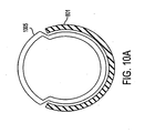
- Figure 10 also illustrates alignment portion 1005 built into the moveable member 1001.
- Alignment portion 1005 is formed by swaging or crushing only a portion of the outer diameter of the tube.
- a more detailed view of the alignment portion is shown in the side view of Figure 10A .
- the advantage to forming the alignment portion 1005 is that it causes the moveable member 1001 always to intersect with the socket 801 in a manner that aligns the moveable member 1001 with the socket 801. This alignment is possible because the flexible member not only moves into and out of the socket, but its flexibility allows it to twist as needed to conform its shape to achieve the alignment as necessary. This alignment aids in maintaining the structural integrity of the joint.
- This alignment also forms a substantially smooth surface around the circumference of the alignment portion 1005 of moveable member 1001 and socket 801.
- the proximate end portion 1009 of full outer diameter portion 1007 of the moveable member 1001 is sized to intersect the end portion 1011 of the snap fit section 807 of socket 801.
- the outer diameter of section 1007 and the outer diameter of the alignment portion 1005 with snap fit portion 807 are substantially the same, forming a smooth transition between the mechanical joint and the frame member integrated with moveable member 1001.
- Figure 10 also illustrates the connection between flexible member 901 and moveable member 1001.
- Moveable member 1001 is generally formed of material having a tubular shape or a shape compatible with the shape of socket 801. End 909 of flexible link 901 inserts into the tube as shown in Figure 10 .
- the length of flexible member that inserts into the tube need only be sufficient to maintain a good connection with the moveable member 1001.
- the connection between the flexible member 901 and the moveable member 1001 can be made by any method suitable for the stresses of the application, for example by gluing, crimping or bolting.
- the flexible member 901 can be reinforced at the connection with the moveable member to enhance its structural integrity either by integrating structure enhancing material into the flexible member or by other means.
- Figure 10 shows flexible member 901 connected to the moveable member 1001 using a bolt, preferably reinforced by a mount ring.
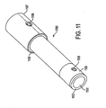
- FIG 11 illustrates an example of a flexible member, although those of ordinary skill will recognize that other flexible member implementations can be used while remaining within the scope of the invention.
- Figure 11 also illustrates the use of mount rings for the additional purpose of assembling the flexible member.
- the flexible member 1100 in Figure 11 has an internal cord 1101 formed, for example, from a solid piece of EPDM rubber.
- Surrounding the central cord 1101 is a sheathing of hose, such as hot water heater hose 1103.
- This hot water heater hose protects the rubber core from damage resulting from exposure to ultraviolet radiation and from other mechanical damage that may occur during the remaining assembly steps.
- Hot water heater hose sheathing 1103 is also useful for its textile reinforcement, which prevents rips and tears from propagating to the entire hose.
- a reinforcing member such as mount ring 1105, provides structural integrity to the one end of the flexible member.
- mount ring 1007 provides structural integrity to the other end of the flexible member.
- These mount rings are typically metal or other reinforcing material that will not tear away from the mounting structure used to attach the flexible member to the socket and moveable member.
- mount rings 1105 and 1107 are shown with bolt holes 1106 and 1108, for connecting to the socket and moveable member, respectively.
- the mount rings are swaged or squeezed around the components of the structural member and therefore also function to assist in holding the internal components of the flexible member 1100 together. Often the dimensions of the connection to the socket and the connection to the moveable member differ.
- Figure 11 shows spa-flex hose 1109 or other application suitable material used to take up the space between the outer diameter of the assembly and the inner diameter of mount ring 1107.
- Figure 12 illustrates optional additional parts of a joint according to the invention, including a sleeve 1201.
- two frame members 1203 and 1205 are engaged such that they are linked together, most typically in an assembled position.
- the joint according to the invention merely links to members in either of two positions, a first position in which the moveable member is engaged in the socket and a second position in which the movable member is not engaged in the socket.
- first position suggests an assembled state
- the second position suggests a collapsed state
- the joint according to the invention can be used in circumstances where either position in a particular structure represents an assembled or collapsed state.
- sleeve 1201 is shown between up stops 1207 and down stops 1209 such as a double spring detent.
- Another detent spring not shown protrudes out the opposite side of the joint.
- One such device is a model D181 detent made by Valco Valley Tool & Die.
- the detent spring 1209 prevents lock sleeve 1201 from going out of position when the moveable member is disengaged from the socket.
- the up stop, 1207 prevents the lock sleeve from moving out of position in the opposite direction.
- a down stop 1211 prevents lock sleeve 1201 from dropping past the socket on the opposite end.
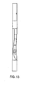
- Figure 13 illustrates conditions when lock sleeve 1201 is engaged. As Figure 13 illustrates, lock sleeve 1202 slides down over the detent spring to form a relatively consistent outer diameter surface in the engaged position.
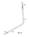
- Figure 14 illustrates an L-shaped frame member 1401 with a socket portion 1403 integrated into one end and a moveable member 1405 integrated into a second end.
- the moveable member will move in and out of a socket when the L-shaped member is assembled with other members into a frame.
- Any combination of sockets and moveable members can be integrated into frame members to be linked to other frame members.
- sockets and moveable members can be formed as individual units to be connected to frame members by any suitable means.
- Moveable member 1405 is formed with a smaller outer diameter than the frame element 1407.
- a rubber stopper 1409 in the moveable member provides additional strength.
- Figure 15 illustrates one possible arrangement for forming a game goal, such as a lacrosse goal, shown generally at 1500.
- Figure 15 is by way of illustration and not limitation, as those of ordinary skill will recognize that an almost infinite variety of such devices can be formed using a joint according to the invention.
- the goal in Figure 15 has four elbows 1501, 1502, 1503 and 1504, each having a frame element extending from each side of the elbow in a direction appropriate to the shape of the goal.
- the frame members are integrated with the elbows, although the elbows and frame members can be formed separately and connected together without departing from the scope of the invention.
- Two straight members 1505 and 1506 are also used in the structure.
- Frame element 1507 extending from elbow 1501 is used as part of a top crossbar of goal 1500 and is configured at its end to form a moveable member according to the invention 1511 that moves into and out of a socket portion according to the invention 1513 at an end of a fixed frame member 1515.
- Member 1515 forms a second portion of the crossbar and is connected or integral with elbow 1502.
- Both elbows 1501 and 1502 have upright portions 1509 and 1517 extending therefrom. These move into and out of socket portions 1523 and 1525, respectively, in the engaged and disengaged positions, depending on whether the goal is configured for use or collapsed for transport.
- FIG. 15 illustrates that according to the invention a structural member can have the same kind of joint portion at either end, as shown by the moveable portions 1511 and 1519 at the ends of both frame elements extending from elbow 1501, or different joint portions at either end, as shown by the socket portion 1513 at the end of one frame element 1515 extending from elbow 1502 and the moveable portion 1521 at the end of the other frame element 1517 extending from elbow 1502.
- Elbows 1503 and 1504 have upright frame elements 1527 and 1529 with socket ends 1523 and 1525, respectively.
- Ground frame elements 1531 and 1533 are also connected to or integral with elbows 1503 and 1505, as shown in Figure 15 .
- Frame elements 1531 and 1532 connect to straight frame members 1505 and 1506, which are used as ground members, through bracket joints 1535 and 1537.
- the straight members connect at a point 1539 required for the shape of a lacrosse goal through another bracket joint.
- Figure 17 illustrates a bracket joint 1701 which acts as a hinge that can be make a straight connection or a connection in a wide variety of positions.
- a flexible member 1703 such as a flexible member previously disclosed herein or other flexible member as may be appropriate to the application, extends between end portions of the members 1505 and 1506. Reinforcing rings 1705 and 1707 may also be used.
- Bolt holes 1709 and 1711 are used with generally U-shaped bracket 1717 and bolts 1715 and 1717 to maintain the bracket joint in the desired position.
- bracket 1713 is screwed to the joint with bolts 1715 and 1717 through holes 1707 and 1709 to hold the joint in position.
- Figure 18 illustrates the bracket joint 1701 in the assembled condition.
- Figure 19 illustrates the goal of Figure 15 in a collapsed position. Note that in the collapsed configuration straight ground members 1505 and 1506 fold toward elbows 1503 and 1504 thereby minimizing the size of the apparatus when collapsed. The goal thus folds into an easily transported L-shape. Rubber stoppers 1901 can be inserted into the ends portions of the frame members at bracket joints 1535 and 1537 to add structural integrity at the reduced diameter portion at the end of the frame element connected to thereto.
- Figure 20 shows a fastener, such as self tapping screw 2002 connecting a net 2000 having a hem 2003 to the frame through fastener strap 2001.
- Fastener strap 2001 is woven around the net 2000.
Landscapes
- Health & Medical Sciences (AREA)
- General Health & Medical Sciences (AREA)
- Physical Education & Sports Medicine (AREA)
- Quick-Acting Or Multi-Walled Pipe Joints (AREA)
- Joints Allowing Movement (AREA)
- Rigid Pipes And Flexible Pipes (AREA)
- Special Chairs (AREA)
- Mutual Connection Of Rods And Tubes (AREA)
Claims (20)
- Eine mechanische Verbindung mit:einer hohlen Struktur, die einen Kanal aufweist;einem flexiblen verwindungsfähigen Element (901), undeinem bewegbaren Element (1001),dadurch gekennzeichnet, dass der Kanal einen Wandbereich enthält, der einen Sockel (801) bildet, in welchem das bewegbare Element angeordnet werden kann,ein erstes Ende des flexiblen verwindungsfähigen Elements in dem Sockel befestigt ist, ein zweites Ende des flexiblen verwindungsfähigen Elements an dem bewegbaren Element angebracht ist, und das bewegbare Element in den Sockel hinein und aus diesem heraus bewegbar ist,wobei der Sockel einen Bereich des Kanals, dessen Wände zusammengeführt worden sind, um eine Doppelwand des Sockels zu bilden, aufweist, in welchem der Sockel eine Breite einer Öffnung hat, die kleiner ist als eine maximale innere Breite des Sockels, in welchem die maximale innere Breite des Sockels im Wesentlichen gleich ist einem äußeren Durchmesser des bewegbaren Elements.
- Eine mechanische Verbindung gemäß Anspruch 1, wobei die Doppelwand aufgrund der Faltung des Kanals auf sich selbst kontinuierlich ist.
- Eine mechanische Verbindung gemäß Anspruch 2, wobei die Verbindung ein eingepasstes Gebiet des Sockels mit einer Krümmung derart aufweist, dass die Breite der Öffnung (703) des Sockels (801) kleiner ist als eine maximale innere Breite des Sockels, wobei das eingepasste Gebiet ein Gebiet ist, in welchem das bewegbare Element angeordnet werden soll.
- Eine mechanische Verbindung gemäß Anspruch 3, wobei das eingepasste Gebiet eine Schnappverbindung mit einem bewegbaren Element (1001), das in dem Sockel angeordnet ist, bereitstellt.
- Eine mechanische Verbindung gemäß Anspruch 3, wobei der Sockel ferner ein Übergangsgebiet benachbart zu dem eingepassten Gebiet aufweist, wobei das Übergangsgebiet darin eine Öffnung aufweist und einen Übergangsbereich bildet, in welchem der Wandbereich sich in der Form in Bezug auf einen Abstand zu dem eingepassten Gebiet ändert.
- Eine mechanische Verbindung gemäß Anspruch 1, wobei der Sockel ein integraler Bestandteil eines strukturellen Elements eines Spieltores ist.
- Eine mechanische Verbindung gemäß Anspruch 1, die ferner einen Montagering (905) aufweist, der den Sockel (801) und das flexible verwindungsfähige Element (901) verbindet, wobei der Montagering fest an einer äußeren Oberfläche des flexiblen verwindungsfähigen Elements angebracht ist, wobei eine Öffnung entlang der Breitenrichtung des flexiblen verwindungsfähigen Elements und des Montagerings vorgesehen ist, so dass eine Befestigungskomponente vollständig durch das flexible verwindungsfähige Element und den Montagering eingepasst werden kann, so dass das flexible verwindungsfähige Element fest an dem Sockel anbringbar ist.
- Eine mechanische Verbindung gemäß Anspruch 7, wobei der Montagering eine Verkleidung an dem ersten Ende des flexiblen verwindungsfähigen Elements umgibt.
- Eine mechanische Verbindung gemäß Anspruch 8, wobei das flexible verwindungsfähige Element ferner einen zweiten Montagering umfasst, der die Verkleidung an dem zweiten Ende des flexiblen verwindungsfähigen Elements umgibt.
- Eine mechanische Verbindung gemäß Anspruch 4, die ferner eine Hülse (1201) aufweist, die auf dem bewegbaren Element (1001) verschiebbar ist, wobei die Hülse eine zylindrische Form besitzt und ausgebildet ist, über einen äußeren Durchmesser des Sockels zu gleiten, so dass das bewegbare Element an dem Sockel befestigbar und nicht aus dem Sockel heraus bewegbar ist, wobei die Hülse eine im Wesentlichen nahtlose Verbindung des Sockels mit dem bewegbaren Element bereitstellt.
- Eine mechanische Verbindung gemäß Anspruch 1, wobei das flexible verwindungsfähige Element (901) umfasst:ein inneres Band (1101), das aus flexiblem Material hergestellt ist;eine Verkleidung (1103), die das innere Band umgibt;einen ersten Montagering (1105), der die Verkleidung an einem Ende davon umgibt, wobei der erste Montagering an dem ersten Ende des flexiblen verwindungsfähigen Elements angebracht ist, wo das eine Ende der Verkleidung angeordnet ist; undeinen zweiten Montagering (1107), der die Verkleidung an einem entgegengesetzten Ende davon umgibt, das an einer gleichen Stelle wie das zweite Ende des flexiblen verwindungsfähigen Elements angeordnet ist, wobei der zweite Montagering an dem zweiten Ende des flexiblen verwindungsfähigen Elements angebracht ist, wo das entgegengesetzte Ende der Verkleidung angeordnet ist.
- Eine mechanische Verbindung gemäß Anspruch 1, wobei das flexible verwindungsfähige Element an dem Sockel an einer Position innerhalb eines maximalen äußeren Durchmessers des Kanals angebracht ist.
- Ein Verfahren zur Herstellung einer mechanische Verbindung, gekennzeichnet durch die Schritte:Verformen eines Teils einer hohlen Struktur, die einen Kanal aufweist;Zusammenrücken von Enden des verformten Bereichs der hohlen Struktur, die den Kanal aufweist, so dass die Wände zusammengebracht werden, um den Bereich in einen Doppelwandsockel (801) zu formen, wobei der Sockel eine Öffnung mit einer Breite besitzt, die kleiner ist als eine maximale innere Breite des Sockels; undBefestigen eines ersten Endes eines flexiblen verwindungsfähigen Elements (901) in dem Sockel, wobei das erste Ende des flexiblen verwindungsfähigen Elements auch ein zweites Ende aufweist, das sich in den Sockel (801) hinein und aus diesem heraus bewegen kann unddas mit einem bewegbaren Element verbunden ist;wobei die maximale innere Breite des Sockels im Wesentlichen gleich ist einem äußeren Durchmesser des bewegbaren Elements, wodurch das bewegbare Element so ausgebildet ist,dass es in den Sockel verschiebbar ist, um das bewegbare Element in den Sockel einzupassen.
- Ein Verfahren gemäß Anspruch 13, wobei Verformen des Bereichs der hohlen Struktur umfasst: Erweitern einer Breite in einem ersten Bereich (105) der hohlen Struktur und Verschmälern der Breite in einem zweiten Bereich (107) der hohlen Struktur ausgehend von der erweiterten Breite auf eine kleinere Breite als die erweiterte Breite, wobei der erste Bereich (105) der hohlen Struktur und der zweite Bereich (107) der hohlen Struktur separate Gebiete des Bereichs der hohlen Struktur sind, der verformt und zusammengedrückt ist.
- Ein Verfahren gemäß Anspruch 14, wobei der Schritt des Zusammendrückens umfasst: Abflachen des ersten Bereichs zu einem im Wesentlichen abgeflachten Bereich.
- Ein Verfahren gemäß Anspruch 15, wobei der Schritt des Zusammendrückens ferner umfasst: Formen des abgeflachten Bereichs zu dem Sockel, so dass der Sockel eine gekrümmte Form erhält.
- Ein Verfahren gemäß Anspruch 13, das umfasst: Bereitstellen eines Montagerings zum Anbringen des bewegbaren Elements (1001) an dem zweiten Ende des flexiblen verwindungsfähigen Elements.
- Ein Verfahren gemäß Anspruch 14, das umfasst: Verschmälern des zweiten Bereichs der hohlen Struktur durch Verwenden einer Vortriebseinrichtung mit einem im Wesentlichen konisch geformten Ende.
- Ein Verfahren gemäß Anspruch 13, das umfasst: Bilden einer im Wesentlichen ringförmigen äußeren Oberfläche in dem bewegbaren Element, so dass damit ermöglicht wird, dass das bewegbare Element durch Schnappverschluss in den Sockel eingepasst wird.
- Ein Verfahren gemäß Anspruch 14, das umfasst: Integrieren des Sockels in ein Strukturelement eines Spieltores.
Applications Claiming Priority (2)
| Application Number | Priority Date | Filing Date | Title |
|---|---|---|---|
| US10/405,475 US7377714B2 (en) | 2003-04-03 | 2003-04-03 | Mechanical joint for collapsible structures |
| PCT/US2004/007699 WO2004094885A2 (en) | 2003-04-03 | 2004-03-31 | Mechanical joint for collapsible structures |
Publications (3)
| Publication Number | Publication Date |
|---|---|
| EP1631748A2 EP1631748A2 (de) | 2006-03-08 |
| EP1631748A4 EP1631748A4 (de) | 2006-04-12 |
| EP1631748B1 true EP1631748B1 (de) | 2012-11-07 |
Family
ID=33097108
Family Applications (1)
| Application Number | Title | Priority Date | Filing Date |
|---|---|---|---|
| EP04724934A Expired - Lifetime EP1631748B1 (de) | 2003-04-03 | 2004-03-31 | Mechanische verbindung für zusammenklappbare strukturen |
Country Status (4)
| Country | Link |
|---|---|
| US (1) | US7377714B2 (de) |
| EP (1) | EP1631748B1 (de) |
| CA (1) | CA2520911C (de) |
| WO (1) | WO2004094885A2 (de) |
Families Citing this family (8)
| Publication number | Priority date | Publication date | Assignee | Title |
|---|---|---|---|---|
| ES2544457T3 (es) | 2009-01-09 | 2015-08-31 | First Goal Llc | Portería de fútbol |
| NO331348B1 (no) * | 2009-11-02 | 2011-12-05 | Anders Alf Wennesland | Mål for ballspill |
| US8657521B2 (en) | 2011-01-13 | 2014-02-25 | First Goal Llc | Collapsible structures and joints for collapsible structures |
| CN103541964A (zh) * | 2013-10-30 | 2014-01-29 | 李理 | 一种垫圈型连接柱 |
| US20160318699A1 (en) * | 2015-04-30 | 2016-11-03 | Honeywell International Inc. | Multi-chamber aircraft part packaging with ordered part arrangement and labeling and methods thereof |
| PE20181607A1 (es) * | 2016-03-02 | 2018-10-09 | Naranjo Oscar Ivan Miranda | Sistema para recoleccion y transporte de frutas similares, desde laderas de cerros o lo similar |
| US11148027B2 (en) * | 2019-07-13 | 2021-10-19 | Ao Jie Plastic Toys Factory Ltd. | Collapsible sports net with quick release folding center joints |
| US11684837B2 (en) | 2021-07-09 | 2023-06-27 | First Goal, LLC | Collapsible field game goal |
Family Cites Families (53)
| Publication number | Priority date | Publication date | Assignee | Title |
|---|---|---|---|---|
| US653796A (en) * | 1900-01-29 | 1900-07-17 | H S Dukes | Type-writer-ribbon clamp. |
| US884634A (en) * | 1906-02-15 | 1908-04-14 | Henry T Bragg | Hose. |
| US1036143A (en) * | 1911-02-21 | 1912-08-20 | Henry Deutsch | Terminal for igniters. |
| US1405312A (en) * | 1920-06-05 | 1922-01-31 | Miller Edward | Slat for binder aprons |
| US1995420A (en) * | 1933-08-25 | 1935-03-26 | Fischer Charles | Flexible shafting |
| US2165472A (en) * | 1936-10-28 | 1939-07-11 | Nat Machinery Co | Axle and method of making same |
| US2408907A (en) * | 1944-08-31 | 1946-10-08 | Noblitt Sparks Ind Inc | Metal furniture |
| US2834321A (en) * | 1954-11-09 | 1958-05-13 | Duefrene George | Ball-type writing tip |
| US2881017A (en) * | 1956-10-11 | 1959-04-07 | Jr John Millar | Coupling for tubing |
| US2870619A (en) * | 1957-01-23 | 1959-01-27 | Fidelity Machine Company Inc | Flexible hose |
| FR1247439A (fr) * | 1959-10-21 | 1960-12-02 | Faure Bertrand Ets | Perfectionnements apportés aux procédés et dispositifs pour assembler latéralement entre eux des éléments tubulaires et aux assemblages obtenus par de tels procédés |
| US3223098A (en) * | 1963-09-12 | 1965-12-14 | Jr Charles M Dole | Collapsible shelter construction |
| US3286804A (en) * | 1965-08-24 | 1966-11-22 | Louis L Bernheim | Extensible and retractable delivery tube assembly |
| FR1475006A (fr) * | 1966-02-18 | 1967-03-31 | Tente, notamment pour la plage | |
| US3380767A (en) * | 1966-06-01 | 1968-04-30 | Everett N. Barth | Flop mop |
| US3405721A (en) * | 1966-09-26 | 1968-10-15 | Sporting Inc | Collapsible and portable cabana |
| US3374986A (en) * | 1967-02-02 | 1968-03-26 | Metal Cladding Inc | Demountable rail fence |
| US3508770A (en) * | 1967-11-24 | 1970-04-28 | Torca Inc | Pipe coupling |
| FR2342422A1 (fr) * | 1976-02-25 | 1977-09-23 | Barril Claude | Meuble d'exterieur, notamment siege ou table de jardin |
| US4063830A (en) * | 1976-07-28 | 1977-12-20 | Ban Stephan C | Lockable and separable pivotal connector joint |
| US4183455A (en) * | 1977-12-21 | 1980-01-15 | Carrier Corporation | Lanced tube joint process |
| US4376417A (en) * | 1979-02-21 | 1983-03-15 | Hyde Products, Inc. | Forestay connector |
| FR2491561A1 (fr) * | 1980-10-06 | 1982-04-09 | Renaud Maurice | Assemblages tubulaires sans elements de jonction |
| AU3873985A (en) * | 1984-02-14 | 1985-08-22 | Stephen Cole | Clamping connection of elongate members |
| DE3430053C1 (de) * | 1984-08-16 | 1986-01-02 | Phoenix Ag, 2100 Hamburg | T-Schlauch |
| US5070597A (en) * | 1985-07-19 | 1991-12-10 | Raychem Corporation | Tubular article |
| US4603904A (en) * | 1985-08-12 | 1986-08-05 | Shelby Williams Industries, Inc. | Chair with articulated, flexible spring backrest |
| US4958582A (en) * | 1987-06-01 | 1990-09-25 | Vermillion James L | Spinnaker sail for kayaks, canoes or other small water craft |
| GB8728903D0 (en) * | 1987-12-10 | 1988-01-27 | Secr Defence | Folding linkage |
| US4875794A (en) * | 1987-12-23 | 1989-10-24 | Dana Corporation | Preloaded steering ball joint assembly and method |
| US4979531A (en) * | 1988-03-25 | 1990-12-25 | Toor John W | Tent pole and method of manufacture therefor |
| US4865064A (en) * | 1988-07-08 | 1989-09-12 | Parsons Thomas O | Hinge apparatus |
| US4928634A (en) * | 1988-12-15 | 1990-05-29 | Voigt Dean J | Honda breakaway |
| US5088675A (en) * | 1990-11-13 | 1992-02-18 | Frederick Perrault | Overhead hanger |
| US5332281A (en) * | 1992-04-30 | 1994-07-26 | Ford Motor Company | Space frame construction |
| US6220776B1 (en) * | 1994-08-10 | 2001-04-24 | Francis J. Reeves | Joint for collapsible structures |
| US6561931B1 (en) * | 1994-08-10 | 2003-05-13 | Francis J. Reeves | Joint for facilitating fabrication of collapsible assemblies |
| US5681231A (en) * | 1994-08-10 | 1997-10-28 | Reeves; Francis J. | Collapsible game goal |
| US5746533A (en) * | 1994-10-24 | 1998-05-05 | Schmidt; Todd W. | Lockable hinge mechanism |
| US5539957A (en) * | 1994-10-24 | 1996-07-30 | Schmidt; Todd W. | Collapsible goal having an articulated frame |
| US5566952A (en) * | 1996-01-24 | 1996-10-22 | Moving Target Sports, Inc. | Foldable sports goal structure |
| US5649866A (en) * | 1996-03-22 | 1997-07-22 | Balwanz; C. Grant | Amusement ride system |
| US5678824A (en) * | 1996-08-05 | 1997-10-21 | Fortier; Kelly F. | Portable target stand |
| AU3321497A (en) * | 1996-08-09 | 1998-02-12 | Gale Pacific Pty. Ltd. | Portable protective structure |
| US5842940A (en) * | 1997-07-24 | 1998-12-01 | Macaluso; Anthony G. | Multi-use net |
| US6241630B1 (en) * | 1998-10-13 | 2001-06-05 | Michael A. Alberti | Collapsible sport pole |
| US6711783B2 (en) * | 1998-11-12 | 2004-03-30 | Lemole John M. | Anti-pinch knuckle for bidirectional sleeve |
| US6014794A (en) * | 1999-03-25 | 2000-01-18 | Mc Coy; Patrick M. | Reinforced bungee cord tie down |
| US6164504A (en) * | 1999-04-30 | 2000-12-26 | Richard; Michael J. | Clothes hanger extender |
| US6292987B1 (en) * | 1999-06-22 | 2001-09-25 | Brian H. Combes | Tie down device and method of use |
| US6558279B1 (en) * | 1999-07-08 | 2003-05-06 | Tracy Goldwitz | Collapsible sports goal assembly |
| DE20019122U1 (de) | 2000-11-06 | 2001-03-08 | Goroshanin, Juri, 13403 Berlin | Fußballtor |
| US6508770B1 (en) * | 2001-03-08 | 2003-01-21 | Acuson Corporation | Aperture compounding for medical imaging |
-
2003
- 2003-04-03 US US10/405,475 patent/US7377714B2/en not_active Expired - Lifetime
-
2004
- 2004-03-31 WO PCT/US2004/007699 patent/WO2004094885A2/en not_active Ceased
- 2004-03-31 CA CA2520911A patent/CA2520911C/en not_active Expired - Lifetime
- 2004-03-31 EP EP04724934A patent/EP1631748B1/de not_active Expired - Lifetime
Also Published As
| Publication number | Publication date |
|---|---|
| US7377714B2 (en) | 2008-05-27 |
| CA2520911C (en) | 2014-02-18 |
| WO2004094885A3 (en) | 2005-02-10 |
| US20040197138A1 (en) | 2004-10-07 |
| EP1631748A2 (de) | 2006-03-08 |
| WO2004094885A2 (en) | 2004-11-04 |
| EP1631748A4 (de) | 2006-04-12 |
| CA2520911A1 (en) | 2004-11-04 |
Similar Documents
| Publication | Publication Date | Title |
|---|---|---|
| US5761852A (en) | Shielding device with inflatable frame structure | |
| CA2520911C (en) | Mechanical joint for collapsible structures | |
| US8469045B2 (en) | Collapsible tent frame | |
| JPS61122388A (ja) | はしご及びその製作方法 | |
| CN104838076A (zh) | 遮篷式遮蔽 | |
| JPH01250570A (ja) | 携帯式構造体 | |
| US5551463A (en) | Skeleton for a telescopic umbrella | |
| US20030111839A1 (en) | End fitting for tubular members and method of applying same | |
| CN203248477U (zh) | 一种伸缩杆连接结构 | |
| US6099024A (en) | Golf cart collapsible device | |
| EP1120057A1 (de) | Zusammenklappbarer Regenschirm | |
| US6241630B1 (en) | Collapsible sport pole | |
| KR20000016308A (ko) | 토오크 조인트 제조 방법 및 성형 다이 | |
| CA2155792C (en) | Rigid end socket for flexible tubing and method of making same | |
| US3484931A (en) | Method of joining a ladder rung to a side rail | |
| US7654943B2 (en) | Collapsible hoop | |
| US6505443B1 (en) | Collapsible structural element | |
| US20030213513A1 (en) | Expandable framework structure for a canopy | |
| US3415107A (en) | Tube bending mandrel | |
| HU217512B (hu) | Beverőék | |
| CN116181832A (zh) | 翻转形成的双壁管和能量吸收翻转管组件 | |
| JP3241463U (ja) | ビニールハウス構築用パイプの連結部材 | |
| EP3774108B1 (de) | Strebe und verfahren zur herstellung einer strebe | |
| US20230349585A1 (en) | Elliptical ducting systems and reinforced connectors | |
| CN202767623U (zh) | 一种帐篷管件连接结构 |
Legal Events
| Date | Code | Title | Description |
|---|---|---|---|
| PUAI | Public reference made under article 153(3) epc to a published international application that has entered the european phase |
Free format text: ORIGINAL CODE: 0009012 |
|
| 17P | Request for examination filed |
Effective date: 20051004 |
|
| AK | Designated contracting states |
Kind code of ref document: A2 Designated state(s): AT BE BG CH CY CZ DE DK EE ES FI FR GB GR HU IE IT LI LU MC NL PL PT RO SE SI SK TR |
|
| A4 | Supplementary search report drawn up and despatched |
Effective date: 20060228 |
|
| RIC1 | Information provided on ipc code assigned before grant |
Ipc: F16B 7/04 20060101ALI20060222BHEP Ipc: A63B 63/00 20060101AFI20060222BHEP Ipc: B21D 39/06 20060101ALI20060222BHEP |
|
| DAX | Request for extension of the european patent (deleted) | ||
| 17Q | First examination report despatched |
Effective date: 20080527 |
|
| GRAP | Despatch of communication of intention to grant a patent |
Free format text: ORIGINAL CODE: EPIDOSNIGR1 |
|
| GRAS | Grant fee paid |
Free format text: ORIGINAL CODE: EPIDOSNIGR3 |
|
| RIN1 | Information on inventor provided before grant (corrected) |
Inventor name: REEVES, FRANCIS J. |
|
| GRAA | (expected) grant |
Free format text: ORIGINAL CODE: 0009210 |
|
| AK | Designated contracting states |
Kind code of ref document: B1 Designated state(s): AT BE BG CH CY CZ DE DK EE ES FI FR GB GR HU IE IT LI LU MC NL PL PT RO SE SI SK TR |
|
| REG | Reference to a national code |
Ref country code: GB Ref legal event code: FG4D |
|
| REG | Reference to a national code |
Ref country code: CH Ref legal event code: EP Ref country code: AT Ref legal event code: REF Ref document number: 582742 Country of ref document: AT Kind code of ref document: T Effective date: 20121115 |
|
| REG | Reference to a national code |
Ref country code: IE Ref legal event code: FG4D |
|
| REG | Reference to a national code |
Ref country code: DE Ref legal event code: R096 Ref document number: 602004039943 Country of ref document: DE Effective date: 20130103 |
|
| REG | Reference to a national code |
Ref country code: AT Ref legal event code: MK05 Ref document number: 582742 Country of ref document: AT Kind code of ref document: T Effective date: 20121107 |
|
| REG | Reference to a national code |
Ref country code: NL Ref legal event code: VDEP Effective date: 20121107 |
|
| PG25 | Lapsed in a contracting state [announced via postgrant information from national office to epo] |
Ref country code: FI Free format text: LAPSE BECAUSE OF FAILURE TO SUBMIT A TRANSLATION OF THE DESCRIPTION OR TO PAY THE FEE WITHIN THE PRESCRIBED TIME-LIMIT Effective date: 20121107 Ref country code: NL Free format text: LAPSE BECAUSE OF FAILURE TO SUBMIT A TRANSLATION OF THE DESCRIPTION OR TO PAY THE FEE WITHIN THE PRESCRIBED TIME-LIMIT Effective date: 20121107 Ref country code: SE Free format text: LAPSE BECAUSE OF FAILURE TO SUBMIT A TRANSLATION OF THE DESCRIPTION OR TO PAY THE FEE WITHIN THE PRESCRIBED TIME-LIMIT Effective date: 20121107 |
|
| PG25 | Lapsed in a contracting state [announced via postgrant information from national office to epo] |
Ref country code: PL Free format text: LAPSE BECAUSE OF FAILURE TO SUBMIT A TRANSLATION OF THE DESCRIPTION OR TO PAY THE FEE WITHIN THE PRESCRIBED TIME-LIMIT Effective date: 20121107 Ref country code: GR Free format text: LAPSE BECAUSE OF FAILURE TO SUBMIT A TRANSLATION OF THE DESCRIPTION OR TO PAY THE FEE WITHIN THE PRESCRIBED TIME-LIMIT Effective date: 20130208 Ref country code: SI Free format text: LAPSE BECAUSE OF FAILURE TO SUBMIT A TRANSLATION OF THE DESCRIPTION OR TO PAY THE FEE WITHIN THE PRESCRIBED TIME-LIMIT Effective date: 20121107 Ref country code: PT Free format text: LAPSE BECAUSE OF FAILURE TO SUBMIT A TRANSLATION OF THE DESCRIPTION OR TO PAY THE FEE WITHIN THE PRESCRIBED TIME-LIMIT Effective date: 20130307 Ref country code: CY Free format text: LAPSE BECAUSE OF FAILURE TO SUBMIT A TRANSLATION OF THE DESCRIPTION OR TO PAY THE FEE WITHIN THE PRESCRIBED TIME-LIMIT Effective date: 20121107 Ref country code: BE Free format text: LAPSE BECAUSE OF FAILURE TO SUBMIT A TRANSLATION OF THE DESCRIPTION OR TO PAY THE FEE WITHIN THE PRESCRIBED TIME-LIMIT Effective date: 20121107 |
|
| PG25 | Lapsed in a contracting state [announced via postgrant information from national office to epo] |
Ref country code: AT Free format text: LAPSE BECAUSE OF FAILURE TO SUBMIT A TRANSLATION OF THE DESCRIPTION OR TO PAY THE FEE WITHIN THE PRESCRIBED TIME-LIMIT Effective date: 20121107 |
|
| PG25 | Lapsed in a contracting state [announced via postgrant information from national office to epo] |
Ref country code: SK Free format text: LAPSE BECAUSE OF FAILURE TO SUBMIT A TRANSLATION OF THE DESCRIPTION OR TO PAY THE FEE WITHIN THE PRESCRIBED TIME-LIMIT Effective date: 20121107 Ref country code: EE Free format text: LAPSE BECAUSE OF FAILURE TO SUBMIT A TRANSLATION OF THE DESCRIPTION OR TO PAY THE FEE WITHIN THE PRESCRIBED TIME-LIMIT Effective date: 20121107 Ref country code: BG Free format text: LAPSE BECAUSE OF FAILURE TO SUBMIT A TRANSLATION OF THE DESCRIPTION OR TO PAY THE FEE WITHIN THE PRESCRIBED TIME-LIMIT Effective date: 20130207 Ref country code: DK Free format text: LAPSE BECAUSE OF FAILURE TO SUBMIT A TRANSLATION OF THE DESCRIPTION OR TO PAY THE FEE WITHIN THE PRESCRIBED TIME-LIMIT Effective date: 20121107 Ref country code: CZ Free format text: LAPSE BECAUSE OF FAILURE TO SUBMIT A TRANSLATION OF THE DESCRIPTION OR TO PAY THE FEE WITHIN THE PRESCRIBED TIME-LIMIT Effective date: 20121107 |
|
| PG25 | Lapsed in a contracting state [announced via postgrant information from national office to epo] |
Ref country code: RO Free format text: LAPSE BECAUSE OF FAILURE TO SUBMIT A TRANSLATION OF THE DESCRIPTION OR TO PAY THE FEE WITHIN THE PRESCRIBED TIME-LIMIT Effective date: 20121107 Ref country code: IT Free format text: LAPSE BECAUSE OF FAILURE TO SUBMIT A TRANSLATION OF THE DESCRIPTION OR TO PAY THE FEE WITHIN THE PRESCRIBED TIME-LIMIT Effective date: 20121107 |
|
| PLBE | No opposition filed within time limit |
Free format text: ORIGINAL CODE: 0009261 |
|
| STAA | Information on the status of an ep patent application or granted ep patent |
Free format text: STATUS: NO OPPOSITION FILED WITHIN TIME LIMIT |
|
| 26N | No opposition filed |
Effective date: 20130808 |
|
| PG25 | Lapsed in a contracting state [announced via postgrant information from national office to epo] |
Ref country code: ES Free format text: LAPSE BECAUSE OF FAILURE TO SUBMIT A TRANSLATION OF THE DESCRIPTION OR TO PAY THE FEE WITHIN THE PRESCRIBED TIME-LIMIT Effective date: 20130218 Ref country code: MC Free format text: LAPSE BECAUSE OF NON-PAYMENT OF DUE FEES Effective date: 20130331 |
|
| REG | Reference to a national code |
Ref country code: CH Ref legal event code: PL |
|
| REG | Reference to a national code |
Ref country code: DE Ref legal event code: R097 Ref document number: 602004039943 Country of ref document: DE Effective date: 20130808 |
|
| REG | Reference to a national code |
Ref country code: IE Ref legal event code: MM4A |
|
| PG25 | Lapsed in a contracting state [announced via postgrant information from national office to epo] |
Ref country code: LI Free format text: LAPSE BECAUSE OF NON-PAYMENT OF DUE FEES Effective date: 20130331 Ref country code: IE Free format text: LAPSE BECAUSE OF NON-PAYMENT OF DUE FEES Effective date: 20130331 Ref country code: CH Free format text: LAPSE BECAUSE OF NON-PAYMENT OF DUE FEES Effective date: 20130331 |
|
| PG25 | Lapsed in a contracting state [announced via postgrant information from national office to epo] |
Ref country code: TR Free format text: LAPSE BECAUSE OF FAILURE TO SUBMIT A TRANSLATION OF THE DESCRIPTION OR TO PAY THE FEE WITHIN THE PRESCRIBED TIME-LIMIT Effective date: 20121107 |
|
| PG25 | Lapsed in a contracting state [announced via postgrant information from national office to epo] |
Ref country code: HU Free format text: LAPSE BECAUSE OF FAILURE TO SUBMIT A TRANSLATION OF THE DESCRIPTION OR TO PAY THE FEE WITHIN THE PRESCRIBED TIME-LIMIT; INVALID AB INITIO Effective date: 20040331 Ref country code: LU Free format text: LAPSE BECAUSE OF NON-PAYMENT OF DUE FEES Effective date: 20130331 |
|
| REG | Reference to a national code |
Ref country code: FR Ref legal event code: PLFP Year of fee payment: 13 |
|
| REG | Reference to a national code |
Ref country code: FR Ref legal event code: PLFP Year of fee payment: 14 |
|
| REG | Reference to a national code |
Ref country code: FR Ref legal event code: PLFP Year of fee payment: 15 |
|
| PGFP | Annual fee paid to national office [announced via postgrant information from national office to epo] |
Ref country code: FR Payment date: 20230322 Year of fee payment: 20 |
|
| PGFP | Annual fee paid to national office [announced via postgrant information from national office to epo] |
Ref country code: GB Payment date: 20230321 Year of fee payment: 20 Ref country code: DE Payment date: 20230321 Year of fee payment: 20 |
|
| REG | Reference to a national code |
Ref country code: DE Ref legal event code: R071 Ref document number: 602004039943 Country of ref document: DE |
|
| REG | Reference to a national code |
Ref country code: GB Ref legal event code: PE20 Expiry date: 20240330 |
|
| PG25 | Lapsed in a contracting state [announced via postgrant information from national office to epo] |
Ref country code: GB Free format text: LAPSE BECAUSE OF EXPIRATION OF PROTECTION Effective date: 20240330 |