EP1631495B1 - Verfahren zur herstellung von verpackungsbehältern aus kunststoff und verpackungsmaschine - Google Patents
Verfahren zur herstellung von verpackungsbehältern aus kunststoff und verpackungsmaschine Download PDFInfo
- Publication number
- EP1631495B1 EP1631495B1 EP04735576A EP04735576A EP1631495B1 EP 1631495 B1 EP1631495 B1 EP 1631495B1 EP 04735576 A EP04735576 A EP 04735576A EP 04735576 A EP04735576 A EP 04735576A EP 1631495 B1 EP1631495 B1 EP 1631495B1
- Authority
- EP
- European Patent Office
- Prior art keywords
- film
- packaging
- packaging container
- sealing
- containers
- Prior art date
- Legal status (The legal status is an assumption and is not a legal conclusion. Google has not performed a legal analysis and makes no representation as to the accuracy of the status listed.)
- Expired - Lifetime
Links
Images















Classifications
-
- B—PERFORMING OPERATIONS; TRANSPORTING
- B29—WORKING OF PLASTICS; WORKING OF SUBSTANCES IN A PLASTIC STATE IN GENERAL
- B29C—SHAPING OR JOINING OF PLASTICS; SHAPING OF MATERIAL IN A PLASTIC STATE, NOT OTHERWISE PROVIDED FOR; AFTER-TREATMENT OF THE SHAPED PRODUCTS, e.g. REPAIRING
- B29C65/00—Joining or sealing of preformed parts, e.g. welding of plastics materials; Apparatus therefor
- B29C65/02—Joining or sealing of preformed parts, e.g. welding of plastics materials; Apparatus therefor by heating, with or without pressure
-
- B—PERFORMING OPERATIONS; TRANSPORTING
- B29—WORKING OF PLASTICS; WORKING OF SUBSTANCES IN A PLASTIC STATE IN GENERAL
- B29C—SHAPING OR JOINING OF PLASTICS; SHAPING OF MATERIAL IN A PLASTIC STATE, NOT OTHERWISE PROVIDED FOR; AFTER-TREATMENT OF THE SHAPED PRODUCTS, e.g. REPAIRING
- B29C51/00—Shaping by thermoforming, i.e. shaping sheets or sheet like preforms after heating, e.g. shaping sheets in matched moulds or by deep-drawing; Apparatus therefor
- B29C51/04—Combined thermoforming and prestretching, e.g. biaxial stretching
-
- B—PERFORMING OPERATIONS; TRANSPORTING
- B29—WORKING OF PLASTICS; WORKING OF SUBSTANCES IN A PLASTIC STATE IN GENERAL
- B29C—SHAPING OR JOINING OF PLASTICS; SHAPING OF MATERIAL IN A PLASTIC STATE, NOT OTHERWISE PROVIDED FOR; AFTER-TREATMENT OF THE SHAPED PRODUCTS, e.g. REPAIRING
- B29C51/00—Shaping by thermoforming, i.e. shaping sheets or sheet like preforms after heating, e.g. shaping sheets in matched moulds or by deep-drawing; Apparatus therefor
- B29C51/26—Component parts, details or accessories; Auxiliary operations
- B29C51/261—Handling means, e.g. transfer means, feeding means
-
- B—PERFORMING OPERATIONS; TRANSPORTING
- B29—WORKING OF PLASTICS; WORKING OF SUBSTANCES IN A PLASTIC STATE IN GENERAL
- B29C—SHAPING OR JOINING OF PLASTICS; SHAPING OF MATERIAL IN A PLASTIC STATE, NOT OTHERWISE PROVIDED FOR; AFTER-TREATMENT OF THE SHAPED PRODUCTS, e.g. REPAIRING
- B29C65/00—Joining or sealing of preformed parts, e.g. welding of plastics materials; Apparatus therefor
- B29C65/78—Means for handling the parts to be joined, e.g. for making containers or hollow articles, e.g. means for handling sheets, plates, web-like materials, tubular articles, hollow articles or elements to be joined therewith; Means for discharging the joined articles from the joining apparatus
- B29C65/7855—Provisory fixing
-
- B—PERFORMING OPERATIONS; TRANSPORTING
- B29—WORKING OF PLASTICS; WORKING OF SUBSTANCES IN A PLASTIC STATE IN GENERAL
- B29C—SHAPING OR JOINING OF PLASTICS; SHAPING OF MATERIAL IN A PLASTIC STATE, NOT OTHERWISE PROVIDED FOR; AFTER-TREATMENT OF THE SHAPED PRODUCTS, e.g. REPAIRING
- B29C66/00—General aspects of processes or apparatus for joining preformed parts
- B29C66/01—General aspects dealing with the joint area or with the area to be joined
- B29C66/05—Particular design of joint configurations
- B29C66/10—Particular design of joint configurations particular design of the joint cross-sections
- B29C66/11—Joint cross-sections comprising a single joint-segment, i.e. one of the parts to be joined comprising a single joint-segment in the joint cross-section
- B29C66/112—Single lapped joints
-
- B—PERFORMING OPERATIONS; TRANSPORTING
- B29—WORKING OF PLASTICS; WORKING OF SUBSTANCES IN A PLASTIC STATE IN GENERAL
- B29C—SHAPING OR JOINING OF PLASTICS; SHAPING OF MATERIAL IN A PLASTIC STATE, NOT OTHERWISE PROVIDED FOR; AFTER-TREATMENT OF THE SHAPED PRODUCTS, e.g. REPAIRING
- B29C66/00—General aspects of processes or apparatus for joining preformed parts
- B29C66/01—General aspects dealing with the joint area or with the area to be joined
- B29C66/05—Particular design of joint configurations
- B29C66/10—Particular design of joint configurations particular design of the joint cross-sections
- B29C66/13—Single flanged joints; Fin-type joints; Single hem joints; Edge joints; Interpenetrating fingered joints; Other specific particular designs of joint cross-sections not provided for in groups B29C66/11 - B29C66/12
- B29C66/131—Single flanged joints, i.e. one of the parts to be joined being rigid and flanged in the joint area
-
- B—PERFORMING OPERATIONS; TRANSPORTING
- B29—WORKING OF PLASTICS; WORKING OF SUBSTANCES IN A PLASTIC STATE IN GENERAL
- B29C—SHAPING OR JOINING OF PLASTICS; SHAPING OF MATERIAL IN A PLASTIC STATE, NOT OTHERWISE PROVIDED FOR; AFTER-TREATMENT OF THE SHAPED PRODUCTS, e.g. REPAIRING
- B29C66/00—General aspects of processes or apparatus for joining preformed parts
- B29C66/01—General aspects dealing with the joint area or with the area to be joined
- B29C66/05—Particular design of joint configurations
- B29C66/20—Particular design of joint configurations particular design of the joint lines, e.g. of the weld lines
- B29C66/21—Particular design of joint configurations particular design of the joint lines, e.g. of the weld lines said joint lines being formed by a single dot or dash or by several dots or dashes, i.e. spot joining or spot welding
-
- B—PERFORMING OPERATIONS; TRANSPORTING
- B29—WORKING OF PLASTICS; WORKING OF SUBSTANCES IN A PLASTIC STATE IN GENERAL
- B29C—SHAPING OR JOINING OF PLASTICS; SHAPING OF MATERIAL IN A PLASTIC STATE, NOT OTHERWISE PROVIDED FOR; AFTER-TREATMENT OF THE SHAPED PRODUCTS, e.g. REPAIRING
- B29C66/00—General aspects of processes or apparatus for joining preformed parts
- B29C66/01—General aspects dealing with the joint area or with the area to be joined
- B29C66/05—Particular design of joint configurations
- B29C66/20—Particular design of joint configurations particular design of the joint lines, e.g. of the weld lines
- B29C66/24—Particular design of joint configurations particular design of the joint lines, e.g. of the weld lines said joint lines being closed or non-straight
- B29C66/242—Particular design of joint configurations particular design of the joint lines, e.g. of the weld lines said joint lines being closed or non-straight said joint lines being closed, i.e. forming closed contours
- B29C66/2422—Particular design of joint configurations particular design of the joint lines, e.g. of the weld lines said joint lines being closed or non-straight said joint lines being closed, i.e. forming closed contours being circular, oval or elliptical
- B29C66/24221—Particular design of joint configurations particular design of the joint lines, e.g. of the weld lines said joint lines being closed or non-straight said joint lines being closed, i.e. forming closed contours being circular, oval or elliptical being circular
-
- B—PERFORMING OPERATIONS; TRANSPORTING
- B29—WORKING OF PLASTICS; WORKING OF SUBSTANCES IN A PLASTIC STATE IN GENERAL
- B29C—SHAPING OR JOINING OF PLASTICS; SHAPING OF MATERIAL IN A PLASTIC STATE, NOT OTHERWISE PROVIDED FOR; AFTER-TREATMENT OF THE SHAPED PRODUCTS, e.g. REPAIRING
- B29C66/00—General aspects of processes or apparatus for joining preformed parts
- B29C66/50—General aspects of joining tubular articles; General aspects of joining long products, i.e. bars or profiled elements; General aspects of joining single elements to tubular articles, hollow articles or bars; General aspects of joining several hollow-preforms to form hollow or tubular articles
- B29C66/51—Joining tubular articles, profiled elements or bars; Joining single elements to tubular articles, hollow articles or bars; Joining several hollow-preforms to form hollow or tubular articles
- B29C66/53—Joining single elements to tubular articles, hollow articles or bars
- B29C66/534—Joining single elements to open ends of tubular or hollow articles or to the ends of bars
- B29C66/5346—Joining single elements to open ends of tubular or hollow articles or to the ends of bars said single elements being substantially flat
- B29C66/53461—Joining single elements to open ends of tubular or hollow articles or to the ends of bars said single elements being substantially flat joining substantially flat covers and/or substantially flat bottoms to open ends of container bodies
-
- B—PERFORMING OPERATIONS; TRANSPORTING
- B29—WORKING OF PLASTICS; WORKING OF SUBSTANCES IN A PLASTIC STATE IN GENERAL
- B29C—SHAPING OR JOINING OF PLASTICS; SHAPING OF MATERIAL IN A PLASTIC STATE, NOT OTHERWISE PROVIDED FOR; AFTER-TREATMENT OF THE SHAPED PRODUCTS, e.g. REPAIRING
- B29C66/00—General aspects of processes or apparatus for joining preformed parts
- B29C66/80—General aspects of machine operations or constructions and parts thereof
- B29C66/83—General aspects of machine operations or constructions and parts thereof characterised by the movement of the joining or pressing tools
- B29C66/832—Reciprocating joining or pressing tools
- B29C66/8322—Joining or pressing tools reciprocating along one axis
-
- B—PERFORMING OPERATIONS; TRANSPORTING
- B29—WORKING OF PLASTICS; WORKING OF SUBSTANCES IN A PLASTIC STATE IN GENERAL
- B29C—SHAPING OR JOINING OF PLASTICS; SHAPING OF MATERIAL IN A PLASTIC STATE, NOT OTHERWISE PROVIDED FOR; AFTER-TREATMENT OF THE SHAPED PRODUCTS, e.g. REPAIRING
- B29C66/00—General aspects of processes or apparatus for joining preformed parts
- B29C66/80—General aspects of machine operations or constructions and parts thereof
- B29C66/84—Specific machine types or machines suitable for specific applications
- B29C66/843—Machines for making separate joints at the same time in different planes; Machines for making separate joints at the same time mounted in parallel or in series
- B29C66/8432—Machines for making separate joints at the same time mounted in parallel or in series
-
- B—PERFORMING OPERATIONS; TRANSPORTING
- B29—WORKING OF PLASTICS; WORKING OF SUBSTANCES IN A PLASTIC STATE IN GENERAL
- B29C—SHAPING OR JOINING OF PLASTICS; SHAPING OF MATERIAL IN A PLASTIC STATE, NOT OTHERWISE PROVIDED FOR; AFTER-TREATMENT OF THE SHAPED PRODUCTS, e.g. REPAIRING
- B29C66/00—General aspects of processes or apparatus for joining preformed parts
- B29C66/80—General aspects of machine operations or constructions and parts thereof
- B29C66/84—Specific machine types or machines suitable for specific applications
- B29C66/849—Packaging machines
-
- B—PERFORMING OPERATIONS; TRANSPORTING
- B65—CONVEYING; PACKING; STORING; HANDLING THIN OR FILAMENTARY MATERIAL
- B65B—MACHINES, APPARATUS OR DEVICES FOR, OR METHODS OF, PACKAGING ARTICLES OR MATERIALS; UNPACKING
- B65B47/00—Apparatus or devices for forming pockets or receptacles in or from sheets, blanks, or webs, comprising essentially a die into which the material is pressed or a folding die through which the material is moved
- B65B47/08—Apparatus or devices for forming pockets or receptacles in or from sheets, blanks, or webs, comprising essentially a die into which the material is pressed or a folding die through which the material is moved by application of fluid pressure
-
- B—PERFORMING OPERATIONS; TRANSPORTING
- B65—CONVEYING; PACKING; STORING; HANDLING THIN OR FILAMENTARY MATERIAL
- B65B—MACHINES, APPARATUS OR DEVICES FOR, OR METHODS OF, PACKAGING ARTICLES OR MATERIALS; UNPACKING
- B65B9/00—Enclosing successive articles, or quantities of material, e.g. liquids or semiliquids, in flat, folded, or tubular webs of flexible sheet material; Subdividing filled flexible tubes to form packages
- B65B9/02—Enclosing successive articles, or quantities of material between opposed webs
- B65B9/04—Enclosing successive articles, or quantities of material between opposed webs one or both webs being formed with pockets for the reception of the articles, or of the quantities of material
- B65B9/042—Enclosing successive articles, or quantities of material between opposed webs one or both webs being formed with pockets for the reception of the articles, or of the quantities of material for fluent material
-
- B—PERFORMING OPERATIONS; TRANSPORTING
- B65—CONVEYING; PACKING; STORING; HANDLING THIN OR FILAMENTARY MATERIAL
- B65D—CONTAINERS FOR STORAGE OR TRANSPORT OF ARTICLES OR MATERIALS, e.g. BAGS, BARRELS, BOTTLES, BOXES, CANS, CARTONS, CRATES, DRUMS, JARS, TANKS, HOPPERS, FORWARDING CONTAINERS; ACCESSORIES, CLOSURES, OR FITTINGS THEREFOR; PACKAGING ELEMENTS; PACKAGES
- B65D1/00—Rigid or semi-rigid containers having bodies formed in one piece, e.g. by casting metallic material, by moulding plastics, by blowing vitreous material, by throwing ceramic material, by moulding pulped fibrous material or by deep-drawing operations performed on sheet material
- B65D1/02—Bottles or similar containers with necks or like restricted apertures, designed for pouring contents
- B65D1/0223—Bottles or similar containers with necks or like restricted apertures, designed for pouring contents characterised by shape
-
- B—PERFORMING OPERATIONS; TRANSPORTING
- B65—CONVEYING; PACKING; STORING; HANDLING THIN OR FILAMENTARY MATERIAL
- B65D—CONTAINERS FOR STORAGE OR TRANSPORT OF ARTICLES OR MATERIALS, e.g. BAGS, BARRELS, BOTTLES, BOXES, CANS, CARTONS, CRATES, DRUMS, JARS, TANKS, HOPPERS, FORWARDING CONTAINERS; ACCESSORIES, CLOSURES, OR FITTINGS THEREFOR; PACKAGING ELEMENTS; PACKAGES
- B65D1/00—Rigid or semi-rigid containers having bodies formed in one piece, e.g. by casting metallic material, by moulding plastics, by blowing vitreous material, by throwing ceramic material, by moulding pulped fibrous material or by deep-drawing operations performed on sheet material
- B65D1/02—Bottles or similar containers with necks or like restricted apertures, designed for pouring contents
- B65D1/0223—Bottles or similar containers with necks or like restricted apertures, designed for pouring contents characterised by shape
- B65D1/0261—Bottom construction
-
- B—PERFORMING OPERATIONS; TRANSPORTING
- B65—CONVEYING; PACKING; STORING; HANDLING THIN OR FILAMENTARY MATERIAL
- B65D—CONTAINERS FOR STORAGE OR TRANSPORT OF ARTICLES OR MATERIALS, e.g. BAGS, BARRELS, BOTTLES, BOXES, CANS, CARTONS, CRATES, DRUMS, JARS, TANKS, HOPPERS, FORWARDING CONTAINERS; ACCESSORIES, CLOSURES, OR FITTINGS THEREFOR; PACKAGING ELEMENTS; PACKAGES
- B65D51/00—Closures not otherwise provided for
- B65D51/18—Arrangements of closures with protective outer cap-like covers or of two or more co-operating closures
- B65D51/20—Caps, lids, or covers co-operating with an inner closure arranged to be opened by piercing, cutting, or tearing
-
- B—PERFORMING OPERATIONS; TRANSPORTING
- B29—WORKING OF PLASTICS; WORKING OF SUBSTANCES IN A PLASTIC STATE IN GENERAL
- B29C—SHAPING OR JOINING OF PLASTICS; SHAPING OF MATERIAL IN A PLASTIC STATE, NOT OTHERWISE PROVIDED FOR; AFTER-TREATMENT OF THE SHAPED PRODUCTS, e.g. REPAIRING
- B29C2791/00—Shaping characteristics in general
- B29C2791/004—Shaping under special conditions
- B29C2791/007—Using fluid under pressure
-
- B—PERFORMING OPERATIONS; TRANSPORTING
- B29—WORKING OF PLASTICS; WORKING OF SUBSTANCES IN A PLASTIC STATE IN GENERAL
- B29C—SHAPING OR JOINING OF PLASTICS; SHAPING OF MATERIAL IN A PLASTIC STATE, NOT OTHERWISE PROVIDED FOR; AFTER-TREATMENT OF THE SHAPED PRODUCTS, e.g. REPAIRING
- B29C2793/00—Shaping techniques involving a cutting or machining operation
- B29C2793/0081—Shaping techniques involving a cutting or machining operation before shaping
-
- B—PERFORMING OPERATIONS; TRANSPORTING
- B29—WORKING OF PLASTICS; WORKING OF SUBSTANCES IN A PLASTIC STATE IN GENERAL
- B29C—SHAPING OR JOINING OF PLASTICS; SHAPING OF MATERIAL IN A PLASTIC STATE, NOT OTHERWISE PROVIDED FOR; AFTER-TREATMENT OF THE SHAPED PRODUCTS, e.g. REPAIRING
- B29C51/00—Shaping by thermoforming, i.e. shaping sheets or sheet like preforms after heating, e.g. shaping sheets in matched moulds or by deep-drawing; Apparatus therefor
- B29C51/02—Combined thermoforming and manufacture of the preform
-
- B—PERFORMING OPERATIONS; TRANSPORTING
- B29—WORKING OF PLASTICS; WORKING OF SUBSTANCES IN A PLASTIC STATE IN GENERAL
- B29C—SHAPING OR JOINING OF PLASTICS; SHAPING OF MATERIAL IN A PLASTIC STATE, NOT OTHERWISE PROVIDED FOR; AFTER-TREATMENT OF THE SHAPED PRODUCTS, e.g. REPAIRING
- B29C51/00—Shaping by thermoforming, i.e. shaping sheets or sheet like preforms after heating, e.g. shaping sheets in matched moulds or by deep-drawing; Apparatus therefor
- B29C51/26—Component parts, details or accessories; Auxiliary operations
- B29C51/261—Handling means, e.g. transfer means, feeding means
- B29C51/262—Clamping means for the sheets, e.g. clamping frames
-
- B—PERFORMING OPERATIONS; TRANSPORTING
- B29—WORKING OF PLASTICS; WORKING OF SUBSTANCES IN A PLASTIC STATE IN GENERAL
- B29C—SHAPING OR JOINING OF PLASTICS; SHAPING OF MATERIAL IN A PLASTIC STATE, NOT OTHERWISE PROVIDED FOR; AFTER-TREATMENT OF THE SHAPED PRODUCTS, e.g. REPAIRING
- B29C51/00—Shaping by thermoforming, i.e. shaping sheets or sheet like preforms after heating, e.g. shaping sheets in matched moulds or by deep-drawing; Apparatus therefor
- B29C51/26—Component parts, details or accessories; Auxiliary operations
- B29C51/30—Moulds
- B29C51/34—Moulds for undercut articles
-
- B—PERFORMING OPERATIONS; TRANSPORTING
- B29—WORKING OF PLASTICS; WORKING OF SUBSTANCES IN A PLASTIC STATE IN GENERAL
- B29C—SHAPING OR JOINING OF PLASTICS; SHAPING OF MATERIAL IN A PLASTIC STATE, NOT OTHERWISE PROVIDED FOR; AFTER-TREATMENT OF THE SHAPED PRODUCTS, e.g. REPAIRING
- B29C51/00—Shaping by thermoforming, i.e. shaping sheets or sheet like preforms after heating, e.g. shaping sheets in matched moulds or by deep-drawing; Apparatus therefor
- B29C51/26—Component parts, details or accessories; Auxiliary operations
- B29C51/42—Heating or cooling
- B29C51/428—Heating or cooling of moulds or mould parts
-
- B—PERFORMING OPERATIONS; TRANSPORTING
- B29—WORKING OF PLASTICS; WORKING OF SUBSTANCES IN A PLASTIC STATE IN GENERAL
- B29C—SHAPING OR JOINING OF PLASTICS; SHAPING OF MATERIAL IN A PLASTIC STATE, NOT OTHERWISE PROVIDED FOR; AFTER-TREATMENT OF THE SHAPED PRODUCTS, e.g. REPAIRING
- B29C65/00—Joining or sealing of preformed parts, e.g. welding of plastics materials; Apparatus therefor
- B29C65/02—Joining or sealing of preformed parts, e.g. welding of plastics materials; Apparatus therefor by heating, with or without pressure
- B29C65/08—Joining or sealing of preformed parts, e.g. welding of plastics materials; Apparatus therefor by heating, with or without pressure using ultrasonic vibrations
-
- B—PERFORMING OPERATIONS; TRANSPORTING
- B29—WORKING OF PLASTICS; WORKING OF SUBSTANCES IN A PLASTIC STATE IN GENERAL
- B29C—SHAPING OR JOINING OF PLASTICS; SHAPING OF MATERIAL IN A PLASTIC STATE, NOT OTHERWISE PROVIDED FOR; AFTER-TREATMENT OF THE SHAPED PRODUCTS, e.g. REPAIRING
- B29C66/00—General aspects of processes or apparatus for joining preformed parts
- B29C66/70—General aspects of processes or apparatus for joining preformed parts characterised by the composition, physical properties or the structure of the material of the parts to be joined; Joining with non-plastics material
- B29C66/71—General aspects of processes or apparatus for joining preformed parts characterised by the composition, physical properties or the structure of the material of the parts to be joined; Joining with non-plastics material characterised by the composition of the plastics material of the parts to be joined
-
- B—PERFORMING OPERATIONS; TRANSPORTING
- B29—WORKING OF PLASTICS; WORKING OF SUBSTANCES IN A PLASTIC STATE IN GENERAL
- B29C—SHAPING OR JOINING OF PLASTICS; SHAPING OF MATERIAL IN A PLASTIC STATE, NOT OTHERWISE PROVIDED FOR; AFTER-TREATMENT OF THE SHAPED PRODUCTS, e.g. REPAIRING
- B29C66/00—General aspects of processes or apparatus for joining preformed parts
- B29C66/70—General aspects of processes or apparatus for joining preformed parts characterised by the composition, physical properties or the structure of the material of the parts to be joined; Joining with non-plastics material
- B29C66/72—General aspects of processes or apparatus for joining preformed parts characterised by the composition, physical properties or the structure of the material of the parts to be joined; Joining with non-plastics material characterised by the structure of the material of the parts to be joined
- B29C66/723—General aspects of processes or apparatus for joining preformed parts characterised by the composition, physical properties or the structure of the material of the parts to be joined; Joining with non-plastics material characterised by the structure of the material of the parts to be joined being multi-layered
-
- B—PERFORMING OPERATIONS; TRANSPORTING
- B29—WORKING OF PLASTICS; WORKING OF SUBSTANCES IN A PLASTIC STATE IN GENERAL
- B29C—SHAPING OR JOINING OF PLASTICS; SHAPING OF MATERIAL IN A PLASTIC STATE, NOT OTHERWISE PROVIDED FOR; AFTER-TREATMENT OF THE SHAPED PRODUCTS, e.g. REPAIRING
- B29C66/00—General aspects of processes or apparatus for joining preformed parts
- B29C66/80—General aspects of machine operations or constructions and parts thereof
- B29C66/82—Pressure application arrangements, e.g. transmission or actuating mechanisms for joining tools or clamps
- B29C66/824—Actuating mechanisms
- B29C66/8242—Pneumatic or hydraulic drives
-
- B—PERFORMING OPERATIONS; TRANSPORTING
- B29—WORKING OF PLASTICS; WORKING OF SUBSTANCES IN A PLASTIC STATE IN GENERAL
- B29C—SHAPING OR JOINING OF PLASTICS; SHAPING OF MATERIAL IN A PLASTIC STATE, NOT OTHERWISE PROVIDED FOR; AFTER-TREATMENT OF THE SHAPED PRODUCTS, e.g. REPAIRING
- B29C66/00—General aspects of processes or apparatus for joining preformed parts
- B29C66/80—General aspects of machine operations or constructions and parts thereof
- B29C66/82—Pressure application arrangements, e.g. transmission or actuating mechanisms for joining tools or clamps
- B29C66/824—Actuating mechanisms
- B29C66/8246—Servomechanisms, e.g. servomotors
-
- B—PERFORMING OPERATIONS; TRANSPORTING
- B29—WORKING OF PLASTICS; WORKING OF SUBSTANCES IN A PLASTIC STATE IN GENERAL
- B29K—INDEXING SCHEME ASSOCIATED WITH SUBCLASSES B29B, B29C OR B29D, RELATING TO MOULDING MATERIALS OR TO MATERIALS FOR MOULDS, REINFORCEMENTS, FILLERS OR PREFORMED PARTS, e.g. INSERTS
- B29K2105/00—Condition, form or state of moulded material or of the material to be shaped
- B29K2105/25—Solid
- B29K2105/253—Preform
- B29K2105/256—Sheets, plates, blanks or films
-
- B—PERFORMING OPERATIONS; TRANSPORTING
- B29—WORKING OF PLASTICS; WORKING OF SUBSTANCES IN A PLASTIC STATE IN GENERAL
- B29L—INDEXING SCHEME ASSOCIATED WITH SUBCLASS B29C, RELATING TO PARTICULAR ARTICLES
- B29L2031/00—Other particular articles
- B29L2031/712—Containers; Packaging elements or accessories, Packages
-
- B—PERFORMING OPERATIONS; TRANSPORTING
- B65—CONVEYING; PACKING; STORING; HANDLING THIN OR FILAMENTARY MATERIAL
- B65D—CONTAINERS FOR STORAGE OR TRANSPORT OF ARTICLES OR MATERIALS, e.g. BAGS, BARRELS, BOTTLES, BOXES, CANS, CARTONS, CRATES, DRUMS, JARS, TANKS, HOPPERS, FORWARDING CONTAINERS; ACCESSORIES, CLOSURES, OR FITTINGS THEREFOR; PACKAGING ELEMENTS; PACKAGES
- B65D2251/00—Details relating to container closures
- B65D2251/0003—Two or more closures
- B65D2251/0006—Upper closure
- B65D2251/0015—Upper closure of the 41-type
-
- B—PERFORMING OPERATIONS; TRANSPORTING
- B65—CONVEYING; PACKING; STORING; HANDLING THIN OR FILAMENTARY MATERIAL
- B65D—CONTAINERS FOR STORAGE OR TRANSPORT OF ARTICLES OR MATERIALS, e.g. BAGS, BARRELS, BOTTLES, BOXES, CANS, CARTONS, CRATES, DRUMS, JARS, TANKS, HOPPERS, FORWARDING CONTAINERS; ACCESSORIES, CLOSURES, OR FITTINGS THEREFOR; PACKAGING ELEMENTS; PACKAGES
- B65D2251/00—Details relating to container closures
- B65D2251/0003—Two or more closures
- B65D2251/0068—Lower closure
- B65D2251/0093—Membrane
Definitions
- the present invention relates to a method of producing packaging containers of plastics and to a packaging machine comprising a molding station.
- packaging containers which have been made from a plastic film could thus not be provided with shapes that have turned out to be advantageous in the glass or ceramic sector or in the case of injection-molded containers.
- packaging containers made from a plastic film it is often not possible to permanently reclose the corresponding filling openings because they are often only closed by a disposable sealing film which after having been tom off cannot be permanently closed again.
- US 6 324 819 B1 discloses a method and an apparatus for producing containers from a strip of moldable synthetic plastic film that is transported longitudinally in a given direction.
- the plastic film is first displaced by at least one plug of the upper mold in a deep-drawing process into a mold cavity of the lower mold and a final molding operation is subsequently performed by a blow-molding process with supply of a gaseous medium into the mold, with the film being placed on a wall of the mold cavity formed in the lower mold.
- Such packaging method and apparatus may be applied for producing packaging containers of a large variety of desired cross-sectional shapes.
- the plastic film is fed in a continuous unseparated sheet form to the mold station, placement errors of the plastic film in the mold station can occur, thereby negatively affecting the manufacturing accuracy of the formed plastic container.
- EP 1 275 580 A1 discloses a method of making filling and closing re-entrant receptacles from a thermoplastic strip. Said method uses a cutter to make initial cuts in the strip leaving attachment points that are broken to separate the recipients once they have been filled and sealed. The cuts are preferably made by fusion of the thermoplastic strip for sterility, and the attachment points are broken by moving pistons applied to the rims of the recipient after filling and sealing.
- EP 1 275 580 A1 only shows to pre-cut the closures for the containers but despite these pre-cuts still a continuous unseparated plastic film is submitted to the forming process with all the disadvantages already referred to with regard to US 6 324 819 B1 .
- a film piece can be exactly dimensioned, cut and oriented prior to being placed in a mold station, in which said singular film piece unconnected to any film web is first displaced by at least one plug of the upper mold in a deep-drawing process into a mold cavity of the lower mold and a final molding operation is subsequently performed by a blow-molding process with supply of a gaseous medium into the mold, with the film being placed on a wall of the mold cavity formed in the lower mold.
- Packaging containers having virtually any desired cross-section of a high standing capacity can thus be produced which exhibit excellent packaging characteristics even at a reduced wall thickness and can e.g. be provided with screw caps, or re-usable caps crimped thereon or attached in snap-fit to either an upper or bottom side of the packaging container.
- the method is particularly advantageous in that unavoidable tensions, dislocations or inaccuracies occurring in the course of processing a continuous web, in particular in conjunction heating and/or cooling steps are avoided by the initial supply of single separate film pieces as a basis for the further manufacturing process.
- the containers comprise an "opening assistant", such as a radially projecting flap or tear tab at the sealing film closing the packaging container (forming an "easy opening” feature), the packaging containers are individually closed (after having been prepared by deep-drawing and blow-molding and filling with a product to be supplied) by respective cover portions separated from a sealing film.
- an "opening assistant" such as a radially projecting flap or tear tab at the sealing film closing the packaging container (forming an "easy opening” feature
- the individual film pieces are moved, after the separation, separately from one another along at least one conveying means, individual stations for forming the finished, filled and closed packaging container being arranged along said conveying means.
- At least one packaging container is formed from each film piece, preferably a plurality of packaging containers is formed from each film piece according to a preferred embodiment
- all the formed film containers are preferably arranged in one row, the arrangement of containers extending preferably perpendicular to the conveying direction, but diagonal or other inclined arrangement of the packaging containers with respect to a travelling direction of the film pieces is also possible as well as staggered disposal of multiple rows in the travelling direction of the film pieces depending on the cross-section of the packaging containers and the width/length ratio of the respective film piece, adapted thereto.
- such packaging containers being individually closed and having an "ear opening assistant", such as a radially projecting flap or “ear” (tear flange or tab) provided through the sealing film cover are partially cut from the film piece surrounding at first, prior to the attaching of the cover portion, then the cover portion (sealing film) separated from a sealing film supply and corresponding essentially to the area of the respective opening of the packaging container is attached, preferably in a two-stage-process, and then the packaging container is finally and completely cut and separated from the surrounding film piece by further cutting the bridging web portions, which so far have still served to transport the pre-fabricated, filled and covered container to the discharge station.
- an "ear opening assistant" such as a radially projecting flap or "ear” (tear flange or tab) provided through the sealing film cover
- Generally cutting of the packaging container from the surrounding individual film piece may occur partially or completely along a prefabricated, predetermined braking line defining an outer circumferential edge of a rim portion of the container.
- the cover portion after having been placed on the feed opening and the surface of the film piece, respectively, is held at several points and then secured to the packaging container, especially by means of spot welding, before it is fully connected to said packaging container by means of welding.
- the packaging container is not completely separated from the film piece (sealing) until it has been completely closed (air tightly sealed) with the sealing film.
- the basic film or the film piece separated therefrom as well as the sealing film are sterilized, especially by exposure to UV radiation, before a material to be packed is filled into the packaging container and the sealing film is applied to said packaging container.
- the afore-indicated objective is performed by a packaging machine having the features of claim 45.
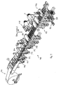
- Figure 1 is a schematic representation of a preferred embodiment of the manufacturing method for producing filled and closed packaging containers of plastic materials, said method being explained in further detail when the description proceeds also in conjunction with the associated machinery and devices used.
- Fig. 1 only for simplicity reasons the containers are displayed to be in a usual conical shape.
- the specifics of the current invention are just focused on the manufacturing of differently shaped containers, namely those which have at least one undercut or a plurality of undercuts and, accordingly, have a longitudinal cross-section contoured to be a combination of negative and positive curses, i.e. having concave and convey portions along their outer walls.
- a plastic basic film 1 being used that can stretched when heated i.e. PS, PVC, PET, PP, multi-layer films comprising such materials and similar films are to be used.
- the packaging basic film 1 in particular being from a plastic film, can also comprise a multi-lid structure and may be flamed, inscribed, decorated, perforated (i.e. composed of a plurality of layers) and may be subject to a corresponding pre-treatment for product identification, i.e. being provided with inscriptions, pictures, labels and other decorative printing.
- a separating station 116 is used, which precedes all the other stations so that individual film pieces or sections, instead of endless films, are processed in the continued process.
- the film pieces 1 a have a rectangular shape with the sides of the rectangular format being disposed perpendicularly to the travelling direction of the film pieces 1 a through the manufacturing line.
- the individual film pieces 1 a are advanced separately from one another to the additional treatment stations by a conveying means 110, the film pieces being held and positioned on said conveying means 110 by holders.
- the conveying means 110 is preferably implemented as a conveyor chain 110a or conveyor belt or as a group of synchronously circulating parallel conveyor chains or belts taking up and supporting each film piece 1 a in the area of its two edges extending at right angles to the conveying direction.
- a reel of basic film 1 as the container forming material said basic film is supplied into the container manufacturing process and respective machinery as shown in Figs, 2 , 3 , 6 and 7 , wherein this reel of basic film 1 has a width that is required by the production capability (capacities) of the machine and a thickness that depends on the size and the tolerance (sufferance) that the containers need to have.
- the size and width of the machine and of the basic film 1 depends on the number and the dimensions of the packaging containers the process machinery will form during each step of the manufacturing process.
- a roller feed mechanism 1 b is provided to supply the basic film 1 under tension from the reel 1 towards the further processing, in particular with a precision mechanism, i.e. in a precise metered way (in particular under the use of a respective servo-motor) to the separating station 116 or the basic film material slicer where the basic film 1 is cut vertically into the respective film pieces 1 a having a size (in particular width in the travelling direction of the film piece 1 a according to the container diameter or other container dimension - in one or a plurality of rows or in a staggered arrangement - and length perpendicular to the travelling direction of the film pieces through the production line determined by the number of packaging containers required.
- a piece transfer mechanism 116a takes the individualized film pieces 1 a and conveys them onto the conveyor chain 110a of the main conveying means 110 utilizing a piece pinning mechanism 116b for temporarily fixing the film pieces 1 a onto the conveyer chain 110a.
- Said conveyor chain 110a having pins and travels along the length and on both sides of the machine frame in guide rails under the drive of a precision motor 80 (see Fig. 6a ).
- the conveyor belts or conveying chains 110a of the conveying means 1 c may be provided with projections plus recesses, clamping means (such as conveyor-based spring, biased pairs of claws or grippers) to fix the film pieces 1 a on the conveyors or the like.
- clamping means such as conveyor-based spring, biased pairs of claws or grippers
- the orientation and synchronization of the film pieces on the conveying means or the conveying belts of the conveying means relative to one another can be effected in a cam-controlled manner or in an electronically-controlled manner by means of process monitoring systems (in particular, using individual servo-motor drives).
- the individual film sections 1 a When the individual film sections 1 a have left the separating station 116 according to the embodiment of Figs. 2 , 3 , they are supplied to a first sterilization station 120, where germs and the like, which may be hazardous to health, are removed therefrom preferably by exposure to UV radiation.
- the sterilization can also take place at a different spot downstream, i.e. in the area preceding a filling station 114, or it can take place between these areas. Depending on the material to be packaged it is also dispensable (see embodiment of Figs. 6 , 7 ).
- the film pieces 1 a are conveyed through one or a plurality of preheating stations 117, as can be seen from Figs. 1 to 3 and 6 to 7.
- preheating stations 117 are arranged in succession so that the film pieces 1 a can be heated to the temperature preferred and required for molding, carefully and under process-specific control.
- infrared radiation methods can just be employed as preheating structures as inductive heating or heating of the film pieces 1 a by heated gas flow.
- infrared radiation methods can just be employed as preheating structures as inductive heating or heating of the film pieces 1 a by heated gas flow.
- pairs of heating plates 117a disposed in the sequence of the three heating stations 117 are provided to perform direct contact to the film pieces 1 a and to heat same directly.
- the respective cantilever operating mechanisms are denoted by 117'.
- the preheating of the film pieces can preferably be multiple and, in the current case, takes place in the three subsequent preheating stations 117.
- the film pieces 1a are preferably pinned or otherwise gripper laterally, so as to be conveyed on the two sides of the conveyor chain 117, while the preheating mechanisms (opposite plates 117a) open and close sequentially by means of the laterally disposed cantilevers operating mechanism 117' and heat the film pieces 1 a by direct contact.
- the temperature is increased towards the way of the film pieces 1 a towards to the molding station and, by the time the film pieces reach the molding station 113 they will possess the required temperature.
- control means are used for the entire heating tools located in the preheating stations 117 or a heating plate comprising special shapes is required or the manufacturing speed if varied.
- control means it is also possible to specifically control partial areas or individual surfaces of the film pieces 1 a as to their preheating.
- preheating and cooling steps with respect to the basic film either upstream of the separating means 116 or, in particular, downstream thereof for local variable temperature control of the packaging film 1 or the individualized (cut) film pieces 1 a.
- a separate or different heating operation may be formed from above and below just as in the present case by direct heating or, for example, also by infrared radiation.
- the film pieces 1 a are supplied to a molding station 113 where the packaging container 3 or other molded plastic parts are produced preferably by a combined deep-drawing and blow-molding, whereby it is also possible to produce packaging containers 3 having undercuts and are provided with threads and bulges, i.e., in particular container of plastic having a negative (radially inwardly convex) and positive (radially outwardly concave) contour.
- the structural design of the molding station 113 reference is made to Figs. 10a - 10e and 11 .
- the film pieces 1 a are preferably designed to have a rectangular form with the longer sides being oriented perpendicularly to the travelling direction through the machinery and, accordingly, also the upper and lower modes in the molding station 113 as well as the cutting tools downstream thereof are oriented perpendicularly to the travelling direction of the film pieces 1a in a row, such as shown in Fig. 11 , also inclined positions of the tooling with respect to the travelling direction, such as shown in WO 98/36894 might be useable in response to the shape and orientation of the respective film strip or film piece 1 a being used in the current system.
- a specific film piece orientation station may also be incorporated into the system (although not used in the current embodiments) if an even more precise orientation and positioning of the individual film pieces 1 a in the way through the machine is required or different types of molding or punching stations are being used which might require a different orientation of the film pieces 1 a.
- an easy exchange of components (stations) may be useful.
- the system uses rectangular film pieces 1 a having a smaller width in the travelling direction that their length extends perpendicularly thereto (for forming a plurality of packaging containers) different shapes and orientation of the film pieces 1 a during their way through the machine are possible.
- a multiple cavity split mold (the cavities are being disposed in a row as, for example, shown in Figs. 2a, 2b , 3a, 3b , 5 , 6a , 6b and 7 ) is used comprising a row or plurality of rows of mold cavity shape according to the desired shape of the packaging container 3, is lifted and holds the preheated material inbetween a counter plug 11 and an upper plug 8, as explained with respect to Figs. 10a -10e hereinafter.
- Fig. 10a -10e reference is also made to Fig.
- the pre-diving plug 8 is also heated and, during descending of same, stretching the film piece 1 a into the mold cavity 12 of the lower mold, clean pressurized air is being introduced from the upper mold through the opening 70, which causes the film of the film piece 1a to stick to the walls of the mold cavity and cool down.
- the multiple cavity split-mode opens laterally and descends while the assistant plug 8 is lifted and returns to its initial position. Said position is shown schematically in Fig. 13 with the finished packaging container 3 still of course adhering to the common piece of the film 1 a.
- the packaging container 3 has a plurality of undercuts which require a split and vertically movable (upwardly and downwardly) lower mold to allow releasing the semi-finished packaging container from the mold after the molding process and easy transportation through the machine along the main chain 110a in the plane of the film piece 1 a. The above process is repeated for every film piece 1 a and is performed many times per minute of the machine operation.
- the conveyor chain 110a moves the respective film piece 1 a with the formed packaging container 3 extending downwardly therefrom into a next optional station 125 (pre-cutting station), which is only there if a packaging container having an "easy opening” feature, such as a radially projecting flap 2d, to assist the opening of a film seal of the container is provided.
- a packaging container having an "easy opening” feature such as a radially projecting flap 2d
- the pre-cutting unit 125 is only shown for the second embodiment of Figs. 6a, 6b and 7 , while said station is omitted in the first embodiment of Figs. 2a, 2b and 3 (as well as in the same embodiment according to Figs. 3a and 3b ).
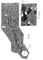
- the film piece 1 a is conducted through the conveyor chain 110a into the pre-cutting station 125, which comprises a cutting tool at the upper part and a split anvil at the bottom part, both components operate together to cut the packaging container 3 from the film strip 1 a partially circumferentially along cutting lines 3b (see Fig. 14 ) forming a sealing rim and container edge portion, but leaving two connecting webs "X" (see Figs. 8, 9 ) at two small spots uncut in order to allow the packaging container 3 to remain connected to the film piece 1 a.
- the pre-cutting station 125 which comprises a cutting tool at the upper part and a split anvil at the bottom part
- Fig. 14 Said features are derivable from Fig. 14 .
- said uncut areas are designated with "X”, while 3a denotes the rim portion of the packaging container 3 arising through the pre-cutting operation as well.
- the film piece 1a shows only one packaging container, but it is understood that normally a plurality of such containers are arranged in a row along the longitudinal edges of the film piece 1 a as shown in the other figures.
- the packaging container that is shown in Fig. 14 with the film strip in plane view, in Fig. 15 is shown in cross-section comprising undercuts, i.e. radially inwardly/outwardly projecting areas, in particular provided also in the area of a thread 35a adapted for fixing a reusable or recloseable screw cap or screw cover thereon in addition to a sealing film which is to be attached to close the upper opening of the packaging container and will be sealed to the sealing rim portion 3a as explained hereinafter.
- the pre-cutting station 125 as shown in Figs. 6a, 6b and 7 , is not present and, as shown in the first embodiment of Figs. 2a, 2b and 3 , the packaging containers, from the mold station 113, would be directly provided to the filling station 114.
- packaging containers 3 which are shown e.g. in Fig. 6a to 6c , have been produced from each film piece, the packaging containers are filled with the material to be packed 104 in the filling station 114.
- the material to be packed which may also consist of a plurality of different individual articles, is supplied from a storage receptacle 105 via a system of conduits to a dosing and/or mixing device 106, which will then supply said material via filler nozzles 107 to the individual packaging containers 3 to be filled.
- a plurality of the above-described filling means may be arranged in succession in said filling station 114.
- Imaginable materials to be packed are liquid as well as solid materials (e.g. yoghurt and Muesli), which may also be filled into separate areas of a packaging container.
- a plurality of packaging containers or other molded plastic parts 3 is formed from each film section 1a in the molding station 113; said packaging containers and molded plastic parts may be identical in shape and size or they may also vary from one another.
- the present packaging containers are preferably arranged in juxtaposed relationship in a row, said row extending at right angles to the conveying direction of the conveying means 110. This has the advantage that a plurality of packaging containers 3 can be produced, filled, closed and subjected to further processing at the same time.
- the formation of only one packaging container from a film piece 1 a is, however, just as easily possible as the formation of 2, 3, 4, 5, 6, 7, 8 or more packaging containers in juxtaposition.
- each film piece 1 a comprises, however, only one packaging container 3 in the conveying direction.
- each film piece 1 a can be oriented with the aid of a positioning means, as has already been described hereinbefore. As can be seen from Fig. 2 to 4 , it is, however, also possible to check each packaging container individually with regard to its position, to orient it and to hold it at the position in question.
- a separate container positioning and holding unit 110b is provided, which approaches the containers preferably from below in the area of the filling station 114 and fixes them at a plurality of positioning points 110a', as can be seen in Fig. 4 , while the packaging containers 3 are being filled.
- Such devices 110b can, additionally or alternatively, also be provided at the subsequent stations.
- the packaging containers 3 When the packaging containers 3 have been filled in the filling station 114 they are supplied by the conveying means 110 (conveyor chain 110a) to the next station, which is a sealing station 115, where a closing material, i.e. a sealing film, chosen according to the needs of the packaged product, is placed in a reel so that the this sealing film 2 is also supplied in the form of an endless film via a second feed means 112 with the aid of conveying means 2c, which is then preferably freed from germs by means of a second stablization device 121 (not shown in the second embodiment of Figs. 6 , 7 ).
- a closing material i.e. a sealing film, chosen according to the needs of the packaged product
- a supply mechanism 140 which feeds the sealing film material with great accuracy in the steps to a punching station or cutting tool 108 where lid grommets, i.e. covers with the "easy open” feature, i.e. a regularly projecting flap 2d as shown in Fig. 16 are being cut, while another mechanism which is based on vacuum sucking action and designated with 109 as a take-up and transfer system picked up the punched out cover portions 2a (having the "easy opening” feature) and places same with high precision onto the filled containers, i.e. along the rim portions 3a thereof.
- a packaging container adapted for placement of the cover portion 2a having the radially projecting opening flap 2d, said cover portion 2a being placed on the rim portion of the filled packaging container 3 (still adhering to the film piece 1 a) at the two opposite , bridging web portions X (uncut), such container 3 is shown in Fig. 16 .
- packaging containers 3 which do not have an "opening assistant", i.e. no regularly projecting flap from the sealing cover portion or other "easy opening” feature, the cutting tool in the punching station 108 would not cut the sealing film 2 in grommets or punched out cover portions 2a of predetermined shape adapted to the sealing rim portion 3a of the respective container but would cut the sealing film 2 in strips which have the same dimensions as the film pieces 1 a.
- the take up and transfer mechanism 109 would then place each sealing material strip onto the corresponding piece of container film 1 a and, to secure the sealing film strip onto the film piece 1a , spot welding would take place in order to avoid inadvertent misplacement between the sealing film strip and the film piece 1a during the transportation to the feeding station 115 where the complete sealing of the cover portions 2a to the respective end portions of the packaging containers takes place.
- the cover portions 2a with the regularly projecting flap i.e. the contoured cutting of the sealing strip cover portions 2a
- the attaching device 103 which is preferably a spot welding device for adhering the cover portion to the peripheral rim of the container at one or several points of the edge of the feed opening.
- the cover portions or lid grommets also cannot be removed or inadvertently displaced on their travels until the film piece 1 a arrives at the sealing station 115 which provides a complete air tight sealing along the respective container rim potion 3a.
- this station utilizes a device with splitted bottom "jaws" 115a as displayed in Fig.
- That sealing operation can be a hot or cold sealing operation performed by application of temperature and/or pressure or can preferably also be done by an ultrasonic welding system. All methods which lead to an airtight sealing and pressure of the sealing opening of the respective packaging container 3 filled with the material to be packed are usable.
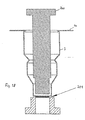
- the packaging containers (which are still connected to the film piece 1 a by the two uncut bridging webs "X") are shifted to a final cutting station 122 which may simultaneously be considered as being a discharge or ejection station where from the bottom part split "jaws" 122a precisely hold the packaging container 3 and lead them to the upper part of the cutting tool therein, where the cutting tool cuts the two bridging web portions "X" where the packaging containers are still attached to the film piece 1 a, said aspect being schematically shown in Fig. 17 with symbolized cutting knives 115' cutting the two so far uncut areas of the pre-cut packaging container 3.
- a cup extracting device 132 descends from above and picks up the finally cut packaging container 3 using vacuum and, after the bottom "jaws" 122a have opened, places the packaging container underneath the cutting tool at a position 133 where another conveyor system, such as a conveyor belt 134, is disposed for transporting the ready containers (formed, filled and sealed) out of the machine.
- Said exit conveyor 134 is specifically shown in Fig. 6b .
- the remaining film piece or strip material (scrap material) after the containers have been removed is still pinned or otherwise grasped at the conveyor chain 110a (at both sides of the machine) while at the turning point of the conveyor chain 110a, designated with the reference numeral 135 in Fig. 6b , the film piece or strip in conjunction with the conveyor chain 110a reaching the end of the machine and starting to descend in order to rotate towards the return path the remainder film piece 1 a loses from the chain pins or other holding means like prebiased claws and is detached.
- the conveyor chain 110a transports the packaging containers 1 a fully connected to the film piece 1 a yet (i.e. not being pre-cut), also to the cutting station 122 as indicated above, the cutting tool cuts out the packaging containers from the film piece 1 a circumferentially and detaches them from the scrap material, that means from the remaining film piece of the basic film strip 1a.
- the extracting tool 132 lowers and picks up the packaging container 3 and places them onto the exit conveyor 134.
- a quality control sensor means (not shown in detail in the drawings) is disposed to remove faulty containers which are then put on a separate faulty cup exit conveyor 135 disposed further downwards of the cutting station 122 and the exit conveyor 134 as shown in Figs. 6a and 6b .
- a quality control sensor means is disposed to remove faulty containers which are then put on a separate faulty cup exit conveyor 135 disposed further downwards of the cutting station 122 and the exit conveyor 134 as shown in Figs. 6a and 6b .
- the method and manufacturing system for producing undercut packaging containers of plastics also allows in a unique way the manufacturing of containers allowing the bottom part thereof to be opened, i.e. to be provided with a sealing film, and, for example, a reusable cover attached thereto which leads to the effect that the original upper side, in use of the packaging container, becomes the lower side (which remains closed by the sealing film apparently) while the former bottom side of the container (during its manufacturing) is adapted to be opened and used for taking out the material to be packaged and eventually to be re-closed in that area by a reusable, for example screw cap or snap fit cap ("reverse forming").
- a cutting tool 200 (see Fig. 18 ) is descending to the respective bottom part and cuts or strips a radial grommet or bottom portion 201. Thereafter, as shown in Fig. 19 , an anvil 202 is descending to the bottom part of the packaging container and holds the uncut container edge while from underneath the packaging container 3 a sealing tool 205 is lifted which provides the sealing of the bottom opening of the container 3a via a single sealing film piece or a continuous sealing strip (for a plurality of containers) 206.
- the sealing action there can also provide temperature and pressure related sealing, i.e. hot or cold sealing or by using ultrasonic waves for performing an airtight seal.
- a plastic plug or cap using a reusable cover.
- Such a cover may also be the only closure means there, i.e. instead of the sealing film 206 also the attachment of a reusable closure cap such as screw or snap fit cap can be the only closure means at that spot.
- a reusable closure cap such as screw or snap fit cap can be the only closure means at that spot.
- such closure could be provided there in conjunction with a tear off section so that later on the cap could be easily released and again attached to the circumference or other portions of the container.
- crimping of a closing film would be possible (instead of sealing), crimping for example an aluminium foil around the circumferential wall portion of the area surrounding the opening of the container. Also this applies to a bottom or upper opening (fill in opening) of said containers.
- the sealing film or closure cap forming material for the upper fill in opening may by the way also be a thermo forming material which can be thermo-formed in the sealing station 115 to be placed on the container by an upper tool 207 in a way as disclosed in Fig. 19 .
- the cover portion 2a is designed to have a reinforced partially hollow but bottom-like structure (non-flat) to be adhered by thermal sealing to the surrounding rim portion 3a of the container 3.
- cover portions 2a may well have an area that is larger than the packaging-container surface area separated from the film piece 1 a so that e.g. a tear tab is provided on the cover portion 2a, said tear tab being not supported by an area of the film piece 1 a or of the packaging container 3 formed therefrom.
- the cover portion 2a can in this way be tom open easily (opening assistant", “easy opening” feature, “radially projecting flaps", as mentioned above.
- a discharge station 119 is provided as preferably last section of the apparatus 100 for producing packaging containers; in said discharge station 119 the singulated packaging containers 3 are packed in batches.
- a product control means 123 may also be provided, which sorts out faulty packaging containers 3 separately or in a condition which they are still connected to the film pieces 1 a.
- the apparatus 100 may also comprise a cover-application station 118 which applies a re-applicable cover, especially a screw cover 35 or snap-fit cover, to the packaging container 3 downstream of the sealing station 115, in particular downstream of the ejection station 122.
- a cover-application station 118 which applies a re-applicable cover, especially a screw cover 35 or snap-fit cover, to the packaging container 3 downstream of the sealing station 115, in particular downstream of the ejection station 122.
- the cover 35 may also be applied to the packaging container 3 prior to the step of filling said packaging container.
- a packaging film that is dimensionally stable to a sufficient extent and suitable for deep-drawing viz. the basic film 1, which consists preferably of a thermoplastic material, is fed and, after having been heated in the preheating station 117, e.g. by means of infrared radiation, it is formed by a combined deep-drawing/blow-molding process into a packaging container making use of the mould configuration which will be described in detail hereinbelow.
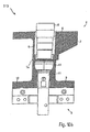
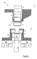
- Fig. 10a shows a vertical sectional view schematically showing, also for the explanation of the method of producing a packaging container 3, an upper mould 4 and a lower mould 5, which are essential parts of the molding station 13 for forming the packaging container 3 through a combined deep-drawing/blow-molding process of the packaging film 1.
- a preferably stepped plug is guided in a vertically movable manner such that the compressed-air chamber 6 is available as an annular chamber between the plug 8 and the receiving body.
- the receiving body 7 is arranged stationarily.
- the packaging film 1 in particular the thermoplastic film, which may also have a multilayered structure and may be flamed, lettered, decorated, perforated (in one or a plurality of layers in each case) and may be subjected to respective pretreatments for product identification, is heated in the preheating station 117 before it is introduced in the molding station 113.
- the packaging containers can also be given a respective design after the molding step.
- infrared radiation methods can just as advantageously be employed as inductive heating or heating of the packaging film 1 by a heated has flow.
- the packaging film 1 should be preheated as homogeneously as possible.
- control means are used for the entire heating tool located in the preheating station 117 or a heating plate for special shapes or for increasing the manufacturing speed.
- suitable sensors it is also possible to specifically control subareas and individual surfaces of the packaging film with regard to their preheating.
- packaging-film heating and cooling steps for a locally variable temperature control of the packaging film 1.
- separate or different heating steps may also be executed from above and below, e.g. in particular by infrared radiation.
- the lower mould 5 which is shown in Fig. 10a in the open condition (the mould in its entirety, which comprises the upper and lower moulds 4, 5, being shown in the open condition as well), comprises two laterally movable lower mould halves 9, 10 as well as a counter plug 11 defining at the bottom side thereof a preferably rotationally symmetrical mould cavity 12, the rest of said mould cavity being defined by the two lower mould halves 9, 10.
- the counter plug 11 in turn, is supported via a bearing body 13 and can also be vertically movable.
- the mould cavity 12 comprises undercuts 14 so that packaging containers 3 having a much greater variety of shapes and a much better standing capacity can be produced by virtue of the special design of the lower mould 5.
- the lower mould halves 9, 10 as well as the counter plug 11 are preferably heated and/or cooled individually. This also applies to the plug 8 and the receiving body 7 of the upper mould.
- the mould in its entirety is therefore preferably made of a material having a high thermal conductivity, preferably an aluminium alloy.
- direct labelling may also be performed inside the molding station by additionally applying a label strip to the mould cavity or by inserting individual labels into the mould cavity 12 (preferably by means of a supply unit or an industrial robot).
- the packaging containers can also be given this kind of design in a subsequent station.
- all elements of the molding station i.e. all the components of the upper and lower moulds 4, 5, in particular the upper plug 8 and the molding elements of the lower mould 5, can be exchanged easily and rapidly.
- the plug material of the plug 8 and of the counter plug 11, respectively, is of particular importance to the sequence of packaging-film molding operations and to material migration inside the mould cavity; in addition, the plug geometry is adapted to the geometry of the mould cavity and a speed profile is chosen for the deep-drawing of the packaging film 1 by the upper plug 8 into the mould cavity 12.
- the plug 8 deep-drawing plunger
- the plug speed is controlled exactly in response to the geometry of the molded packaging body to be produced.
- the plug 8 (deep-drawing plunger) may also be controlled by servomotors instead of pneumatic control means. The plug speed is thus greatly dependent on the plug path, i.e. on the respective immersion depth of the plug into the mould cavity with simultaneous deep-drawing of the packaging film 1 (cf. also Fig. 10c , 10d ).
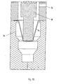
- Fig. 10b shows the closed total mould comprising the upper and lower moulds 4, 5, the lower mould halves 9, 10, in combination with the bottom-side counter plug 11, defining the mould cavity 12, and the receiving body 7 being operative as a hold-down means for the heated packaging film 1.
- the plug 8 is shown in Fig. 10b at the beginning of the deep-drawing process (seated on the packaging film 1).
- Fig. 10c illustrates a first part of the deep-drawing process of the packaging film 1 into the mould cavity 12.
- Fig. 10d shows the plug 8 in its lower end position, and the packaging container 3 is formed by superimposing the end phase of the deep-drawing process with a blow-molding process by blowing compressed air from the compressed-air chamber 6 along the plug 8 into the preformed packaging-container blank; in particular, the lateral shape of the packaging container 3 is produced, and the packaging container 3 is given its final shape in that, due to the blown-in compressed air, the packaging film moves radially away from the plug 8 and comes into full-area contact with the inner wall of the mould cavity 12.
- the plug 8 may optionally be provided with radially and/or axially adjustable elements for a widening or spreading function so that the final shape of the packaging container 3 will already be approached during the deep-drawing process as closely as possible and so that the extent to which the packaging container is deformed by the subsequent blow-molding process, or by a blow-molding process carried out simultaneously with the deep-drawing process during the end phase of said deep-drawing process, will be limited as far as possible.
- the heated packaging film 1 is brought into contact with the wall of the mould cavity 12 of the lower mould 5 due to the air pressure (blow mould), the film will cool down there.
- the plug 8 is withdrawn and the lower mould 5 is opened, as shown in Fig. 7e.
- the lower mould is moved back downwards so that the molded packaging body 3 produced adheres in an integral material structure to the remaining packaging film 1 and can also be transported with said film from the molding station 113 into a subsequent filling station.
- the packaging container 3 may also comprise undercuts 14 without the final molding process presenting any difficulties.
- the packaging container may be provided in its neck portion and also at its bottom with holding projections or other means, such as a round-thread embossing, so that a cover can be screwed on.
- the plug speed, the shape and the temperature of the mould as well as the supply of air must be adapted to one another, just like the material of the mould, including the plug 8, with respect to the material of the packaging film 1.
- the plug speed of the plug 8 (and, if necessary, also a vertical speed of movement of the lower counter plug 11) is/are variably controlled via servomotors or a pneumatic control means.
- the control of the plug temperature of the plug 8 may be locally variable, but is preferably kept constant. The same applies to the design and the pattern of the surface of the plug 8, the control of the mould temperature of the lower mould 5 (uniform or locally variable) and the surface design, in particular as far as the mould cavity 12 of the lower mould 5 is concerned.
- the air temperature of the compressed air blown in for the blow-molding process may also be subjected to special control.
- the plug 8 of a plurality of plugs which, when in operation, move one into the other in a telescopic fashion.
- the mould cavity 12 in the lower mould may e.g. also comprise handle geometries.
- the molding process in this mould is as follows:
- the packaging film 1 is only in slight contact with the lower mould 5 in the neck portion; in this area, the radial gap or distance between the plug 8 and the mould cavity 12 essentially corresponds to the wall thickness of the future packaging container 3 (film thickness) plus a certain motion tolerance.
- the additional blow-molding operation is initiated, especially triggered by the plug 8, (blowing compressed air via the compressed-air chamber 6 downwards into the space between the plug 8 and the preshaped packaging film 1), whereupon the heated packaging film 1 will, due to the air pressure, be brought into contact with the wall of the mould cavity 12 where it will cool down.
- the plug 8 is moved back upwards and the mould is opened (including opening of the lower mould 5); the packaging container 3, which is still connected to the film material (cf. Fig. 10e ), is then transported away from the area of the molding station 113 and advanced to the filling station 114.
- the angle of inclination of the series arrangement is then preferably 45° relative to the direction of movement of the respective film piece. If desired, also a several rows of such molding stations may be provided in parallel in a "gapwise" arrangement.
- Fig. 11 once again exemplifies the disposal of the lower mold with the series arrangement of the mold cavities together with boundary cylinder sections 23 which are each connected to, preferably integral with, opposite guide plates 24, 25.
- Said guide plates 24, 25 in conjunction with guide rails 16 which are secured to the support plate 17 form a lateral guide device for enabling lateral opening of the split lower mold in conjunction with the vertical movement of the support plate 17 along guide columns 26 through mold engaging means of a control cam arrangement, not shown in greater detail here.
- Fig. 21 a to 21 c show embodiments of packaging containers 3 which are made of a thermoplastic material and produced according to the above-discussed method and by means of the above-explained devices.
- reclosable plastic packaging containers 3 can be produced in a particularly advantageous manner by the apparatus according to the present invention, and this is of particularly great advantage to the storing of residual amounts (foodstuff) in the packaging containers and can drastically increase the useful life of the packaging containers 3; this will result in a substantially lower environmental load.
- Fig. 21 a to 21 e show embodiments for packaging containers 3 provided with a screwable cover 35, which is preferably made of a plastic material as well.
- the special feature of these embodiments is that the cover is screwed onto the former "bottom” (related to the manufacturing process) of the packaging container 3 which is provided with a screw thread 36 in this area.
- the screw thread 36 is circumferentially provided in the former bottom area (related to the shaping process), and the container bottom comprises an opening device, i.e.
- the packaging container it is so pre-embossed, prepunched or otherwise weakened in its material thickness that the packaging container can easily be opened on this side so that this side constitutes the side where the user will open the packaging container and take out its content, whereas the sealing film 2 forms the bottom of the packaging container 3 which remains closed during practical use.
- Fig. 21 b shows this type of packaging container 3 without a cover.
- the sealing edge 3a is dimensioned as narrow as possible and a respective tear tab 2d is designed such that said tab can be bent so that it will not be in the way when the cover is screwed on.
- the sealing edge itself may be used as a support for attaching a further cover (snap fit) (optionally in further circumferential contact with the rest of the circumferential wall of the container).
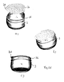
- Figs. 22a, 22b, 22c, 22d show a vase-like container having an undercut area and an upper branch-like rim portion 3a which is preferably sealed with a sealing film (not shown) and can additionally serve as a snap-fit for a re-closable cover (now shown here).
- Fig. 22a shows a front view
- Fig. 22b is a perspective view on the top side
- Fig. 22c is a perspective view of the bottom side with Fig. 20d being a bottom view.
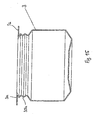
- Fig. 23 shows a subject packaging container 3 with a thread 36 underneath the upper flange or sealing rim portion 3a so that such a container after the upper sealing film has been torn partially off but the container is either not completely emptied and shall be reused for other purposes can be closed by a screw cap or screw cover in a re-closable manner.
- Fig. 23a is a front view while Fig. 23b is a perspective view from the opening side.
- Fig. 24 shows a bottle container which, in Fig. 24a in perspective view, is manufactured according to the "reverse forming" method, i.e. explained with respect to the preceding Figs. 18 and 19 , i.e. the former bottom part was punched here to form the bottle opening having an outer thread 36 to allow a screw cap or screw cover to be screwed thereon while the former fill in opening for the product and respective flange portion 3a closed with the sealing film is now the bottom portion of the bottle.
- Fig. 24b shows a front view thereof where the undercut portions and the combination of positive and negative contour of the bottle manufactured by such method and system as indicated above has been provided.
- Figs. 25a-c show a packaging container with a thread underneath the fill-in opening which is going to be sealed by a film seal cover portion 2a.
- Said film seal portion 2a has a radially projecting flap 2d ("easy opening” feature) for easy opening of the container after removing the closure cap (not shown).
- the container 3 can be re-closed after partially emptying same or can be re-closed for different purposes.
- the thread 36 could be replaced by other closure cap holding means such as radial projections for a snap-fit cover.
Landscapes
- Engineering & Computer Science (AREA)
- Mechanical Engineering (AREA)
- Ceramic Engineering (AREA)
- Physics & Mathematics (AREA)
- Fluid Mechanics (AREA)
- Containers And Plastic Fillers For Packaging (AREA)
- Containers Having Bodies Formed In One Piece (AREA)
Claims (56)
- Verfahren zur Herstellung von Verpackungsbehältern aus Kunststoffen mit einem Basisfilm, der zumindest in Teilen aus einem Kunststoffmaterial besteht, das in eine Form eingeführt wird, die eine obere Form und eine untere Form aufweist, und der Film einem Formgebungsverfahren unterzogen wird, wobei der Basisfilm (1) in die Form in Form von individuellen Filmstücken (1a) zugeführt wird, wobei jedes Filmstück (1a), zugeführt in die Form, zuerst durch zumindest einen Stempel (8) der oberen Form in einem Tiefziehverfahren in einen Formhohlraum (12) der unteren Form (5) verlagert wird, und ein endgültiges Formgebungsverfahren dann durch einen Blasform- Formgebungsverfahren mit Zuführung eines Gasmediums in die Form mit dem Film (1) ausgeführt wird, der an eine Wand des Formhohlraumes (12), gebildet in der unteren Form (5), verlagert wird, wobei der Basisfilm von einer Spule von synthetischem Kunstharzmaterial abgewickelt wird, bevor er zu einem Basisfilmschneider durch eine Zuführvorrichtung für eine genau abgemessene intermittierende Zuführung des Basisfilms (1) in den Basisfilmschneider zugeführt wird, wobei eine Bahn des Basisfilms (1) vor dem Schneiden oder die geschnittenen Filmstücke (1 a) einem Vorerwärmen unterworfen werden, wodurch eine Mehrzahl von Verpackungsbehältern (3) aus jedem abgeschnittenen Filmstück (1 a) gebildet wird, wobei die Verpackungsbehälter (3) jeweils mit zumindest einem Hinterschnitt versehen und nebeneinander in einer Reihe angeordnet sind, während stromab des Formgebens der Verpackungsbehälter aus dem jeweiligen Filmstück (1a) die Behälter (3), die eine Öffnungsunterstützung haben, teilweise gestanzt werden, um zu sichern, dass die Verpackungsbehälter mit dem umgebenden Filmstück (1 a) einstückig bleiben, während jeder Verpackungsbehälter durch einen separaten Deckelabschnitt (2a), der von dem Versiegelungsfilm (2) separiert worden ist, geschlossen wird, während vor dem Verschließen des Verpackungsbehälters, der Deckelabschnitt (2a), nachdem er zu einem Randabschnitt des Verpackungsbehälters durch einen Vakuumtransfer zugeführt worden ist, befestigt wird, wobei nach dem Anheften des Deckelabschnittes (2a) an dem Verpackungsbehälter (3) in einer punktförmigen Weise, ein endgültiges Versiegeln des Deckelabschnittes (2a) an dem Behälter (3) vorgesehen ist.
- Verfahren nach Anspruch 1, wobei der Stempel (8) der oberen Form (4) über den Stempelweg mit einer variablen Geschwindigkeit bewegt wird.
- Verfahren nach Anspruch 1 oder 2, wobei das gasförmige Medium Druckluft ist.
- Verfahren nach zumindest einem der vorhergehenden Ansprüche 1 bis 3, wobei der Stempel (8) und / oder die untere Form (5) einer Temperatursteuerung unterzogen wird, insbesondere zumindest zum Teil erwärmt und / oder gekühlt wird.
- Verfahren nach zumindest einem der vorhergehenden Ansprüche 1 bis 4, wobei, vor der Formgebung der Verpackungsbehälter (3), individuelle Filmstücke (1 a) von dem Basisfilm (1) separiert werden, wobei die Verpackungsbehälter (3) aus den Filmstücken (1a) nach dem Separieren gebildet werden.
- Verfahren nach zumindest einem der vorhergehenden Ansprüche 1 bis 5, wobei der Basisfilm (1) in die individuellen Filmstücke (1 a) geschnitten wird, die eine Breite haben, die zumindest einen Durchmesser oder anderer Abmessung, insbesondere eine Breite eines herzustellenden Verpackungsbehälters haben.
- Verfahren nach zumindest einem der vorhergehenden Ansprüche 1 bis 6, wobei eine Breite des Basisfilms (1) entsprechend eines mehrfachen Durchmessers oder Breitenabmessung des herzustellenden Verpackungsbehälters ausgewählt wird, um an eine Mehrzahl von Verpackungsbehältern angepasst zu sein, die aus demselben individuellen Filmstück (1 a) herstellbar sind, wobei der Verpackungsbehälter nebeneinander in einer Reihe angeordnet ist, wobei die sich erstreckende Reihe geneigt ist, insbesondere rechtwinklig zu der Laufrichtung des Filmstückes (1 a) durch das Verpackungsbehälter- Herstellungssystem, insbesondere einer Formfüll- und Versiegelungs- Maschine.
- Verfahren nach Anspruch 6 oder 7, wobei das Filmstück (1 a) im Wesentlichen einem mehrfachen des Durchmessers des herzustellenden Verpackungsbehälters oder weniger entspricht.
- Verfahren nach Anspruch 8, wobei eine Mehrzahl von vorhergehenden Behältern aus demselben Filmstück (1 a) hergestellt wird, die nebeneinander entlang der Laufrichtung des Filmstückes (1 a) angeordnet sind und in Bezug auf eine vorhergehende Reihe von Verpackungsbehältern, die sich geneigt erstreckt, angeordnet sind, insbesondere rechtwinklig zu der Laufrichtung des Filmstückes (1a) durch das Verpackungsbehälter- Herstellungssystem, insbesondere einer Formfüll- und Versiegelungs- Maschine.
- Verfahren nach zumindest einem der vorhergehenden Ansprüche 1 bis 9, wobei der Basisfilm (1) in individuelle Filmstücke (1a) geschnitten ist, die eine Breite haben, die sich in der Laufrichtung der der Filmstücke (1 a) erstreckt, kleiner als ihre Länge, die sich rechtwinklig zu der Laufrichtung der der Filmstücke (1 a) erstreckt.
- Verfahren nach zumindest einem der vorhergehenden Ansprüche 1 bis 10, wobei das Schneiden des Basisfilms (1) in individuelle Filmstücke (1a) und deren Größe durch den Durchmesser oder andere Abmessung, insbesondere die Breite und die Anzahl der Verpackungsbehälter, gewünscht von einem bestimmten Filmstück (1 a), festgelegt ist.
- Verfahren nach zumindest einem der vorhergehenden Ansprüche 1 bis 11, wobei die Filmstücke (1 a) bevor sie in die Form zugeführt werden wieder- ausgerichtet werden.
- Verfahren nach zumindest einem der vorhergehenden Ansprüche 1 bis 12, wobei die Filmstücke (1 a) separat voneinander entlang zumindest einer Fördereinrichtung (110) bewegt werden.
- Verfahren nach zumindest einem der vorhergehenden Ansprüche 1 bis 13, wobei ein Verpackungsbehälter (3) aus jedem separiertem Filmstück (1 a) gebildet ist, wobei der Verpackungsbehälter (3) besonders mit zumindest einem Hinterschnitt versehen ist.
- Verfahren nach Anspruch 1, wobei eine Mehrzahl der Verpackungsbehälter (3) aus jedem separiertem Filmstück (1 a) gebildet ist, wobei die Verpackungsbehälter (3) ausschließlich nebeneinander in einer Richtung rechtwinklig zu der Förderrichtung der Filmstücke (1 a) angeordnet sind.
- Verfahren nach zumindest einem der vorhergehenden Ansprüche 1 bis 15, wobei die individuell beabstandeten Filmstücke (1a) auf einem Tragförderband oder einer Kette, oder einer Mehrzahl von solchen parallel angeordneter Fördereinrichtungen festgelegt sind, insbesondere festgesteckt oder unter Druck gebracht sind für ein temporäres Befestigen auf dem Förderband oder der Kette, oder durch ketten- oder ein band- gelagerte Befestigungsmittel, wie z. B. vorgespannte Klammern oder Greifer, gehalten werden.
- Verfahren nach Anspruch 16, wobei das Förderband oder die Kette die Filmstücke (1 a) unter Mitwirkung von Stiften trägt, wobei das Förderband oder die Kette, die durch einen Präzisions- Servomotor angetrieben werden, in Führungsschienen entlang der Seiten des Verpackungsbehälter- Herstellungssystems geführt wird.
- Verfahren nach Anspruch 1, wobei die Filmstücke (1a) vor- erwärmt werden, während sie festgesteckt oder auf andere Weise auf zwei Seiten des Förderbandes oder der Kette befestigt sind, befördert werden, insbesondere intermittierend unter direktem Kontakt von sowohl der Ober- als auch der Unterseite der Filmstücke (1 a) vorerwärmt werden.
- Verfahren nach zumindest einem der vorhergehenden Ansprüche 1 bis 18, wobei, zum Bilden eines oder einer Mehrzahl von Verpackungsbehältern aus einem Filmstück (1 a), das angemessen positioniert wird zwischen der oberen und unteren Form, die untere Form, die geteilt ist, um eine jeweilige Anzahl von Formhohlräumen entsprechend der Kontur der (des) Verpackungsbehälter(s) zu bilden, angehoben wird und das Filmstück (1a) zwischen der oberen und der unteren Form hält, wobei das Filmstückmaterial in die jeweiligen Formhohlräume tiefgezogen wird und gegen die Hohlraumformen der unteren Form, um dort anzuhaften, gedrückt werden, während sich nach dem Beenden der Formgebung der Verpackungsbehälter die geteilte untere Form öffnet und absenkt, während der Tiefziehstempel in seine Ausgangsposition zurückgezogen wird.
- Verfahren nach zumindest einem der vorhergehenden Ansprüche 1 bis 19, wobei die Verpackungsbehälter (3), gebildet aus einem Filmstück (1 a), mit einem zu verpackenden (104) Material gefüllt und / oder mit einem Versiegelungsfilm (2) verschlossen werden, bevor sie von dem Filmstück (1 a) separiert werden.
- Verfahren nach Anspruch 20, wobei jeder Verpackungsbehälter (3) durch einen separaten Deckelabschnitt (2a), der von dem Versiegelungsfilm (2) separiert worden ist, verschlossen wird.
- Verfahren nach Anspruch 21, wobei die Fläche des Deckelabschnittes (2a) im Wesentlichen zumindest der Fläche des Verpackungsbehälters (3), separiert von dem Filmstück (1a), entspricht.
- Verfahren nach zumindest einem der vorhergehenden Ansprüche 20 bis 22, wobei der Deckelabschnitt (2a) zusätzlich mit einer Aufreißnase (2b) versehen ist, die nach dem Verbinden des Deckelabschnittes (2a) mit dem Verpackungsbehälter (3) radial von dem Randabschnitt des Verpackungsbehälters (3) vorspringt.
- Verfahren nach zumindest einem der vorhergehenden Ansprüche 20 bis 23, wobei vor dem Schließen des Verpackungsbehälters (3) der Deckelabschnitt (2a), vorgesehen für diesen Zweck, an dem Verpackungsbehälter (3) in einer punktförmigen Weise, besonders mittels Punktschweißen, befestigt wird.
- Verfahren nach zumindest einem der vorhergehenden Ansprüche 20 bis 24, wobei der Verpackungsbehälter (3) durch Schweißen, Heiß- oder Kalt- Versiegeln oder Ultraschallversiegeln an diesem für diesen Zweck vorgesehenen Versiegelungsabschnitt (2a) verschlossen wird, wobei die Deckelabschnitte vorzugsweise von einer Versiegelungsfilmzuführung in Richtung zu den Verpackungsbehältern durch eine Vakuumübertragungseinrichtung übertragen werden.
- Verfahren nach zumindest einem der vorhergehenden Ansprüche 1 bis 19, wobei der Versiegelungsfilm in Streifen geschnitten wird, die in der Form den Filmstücken (1 a) entsprechen, gefolgt von Punktschweißen des jeweiligen Versiegelungsfilmstreifens an den jeweiligen Filmstücken (1 a), die die gefüllten Verpackungsbehälter aufweisen, um dieselben zu verschließen.
- Verfahren nach Anspruch 26, wobei der Versiegelungsfilmstreifen und das Filmstück (1 a), der die gefüllten Verpackungsbehälter aufweist, die bereits grob miteinander entlang der Randabschnitte der geformten, befüllten Verpackungsbehälter befestigt werden, luftdicht durch Heiß- oder Kalt- Versiegeln unter erhöhter Temperatur und / oder Druck, oder durch Ultraschallversiegeln, insbesondere unter Mithilfe eines Randabschnittes des jeweiligen Verpackungsbehälters, von unten versiegelt werden.
- Verfahren nach zumindest einem der vorhergehenden Ansprüche 1 bis 27, wobei die Verpackungsbehälter (3), verschlossen mit dem Versiegelungsfilm, teilweise einstückig mit dem verbliebenen Filmstück (1 a) sind, vorzugsweise abgekühlt und weiter befördert zu einer Schneidestation, um radial zumindest noch die verbliebenen Stege zu schneiden, während die Verpackungsbehälter unter Vakuum durch ein sich absenkendes Werkzeug gehalten werden, die sie auf das Förderband oder die Kette auflegen, um aus der Maschine geführt zu werden.
- Verfahren nach zumindest einem der vorhergehenden Ansprüche 1 bis 28, wobei ein Behälterqualitäts- Überwachungssystem geschaffen ist, vorgesehen fehlerhafte Verpackungsbehälter aus der Maschine zu entfernen.
- Verfahren nach zumindest einem der vorhergehenden Ansprüche 1 bis 25, wobei ein Restabfallfilmstück, nach der Abgabe der Verpackungsbehälter, aufgesteckt auf der Förderkette oder dem Förderband auf beiden Seiten desselben verbleibt, bis zu dem Übergang eines oberen Zuführzuges der Förderkette oder des - bandes in dem unteren Rückführzug der Förderkette oder des -bandes, wo das Restabfallfilmstück (1 a) von den Förderketten- oder -band stiften von den Stiften entfernt und gelöst wird.
- Verfahren nach zumindest einem der vorhergehenden Ansprüche 1 bis 30, wobei der Verpackungsbehälter eine Verschlusseinrichtung aufweist, um damit eine Verschlusskappe zu verbinden.
- Verfahren nach Anspruch 31, wobei die Verschlusseinrichtung auf der Seite des Versiegelungsfilms und / oder auf einer gegenüberliegenden (Boden-) Seite des Verpackungsbehälters zum daran Befestigen der Verschlusskappe vorgesehen sind.
- Verfahren nach zumindest einem der vorhergehenden Ansprüche 31 bis 32, wobei die Verschlusskappe mit der Verschlusseinrichtung in einer Weise eines Schnappverschlusses verbunden ist.
- Verfahren nach zumindest einem der vorhergehenden Ansprüche 31 bis 33, wobei die Verschlusskappe in Eingriff mit einem radial vorspringenden Umfangsvorsprung in einem Schnappverschluss gebracht wird oder, in einem Fall des Ausbildens der Verschlusseinrichtung als eine Verschraubung, daran verschraubt wird.
- Verfahren nach einem der vorhergehenden Ansprüche 31 bis 34, wobei die Verschlusskappe auf einer Verschraubung, vorgesehen in dem Boden- oder HalsBereich des Verpackungsbehälters verschraubt wird, wobei die Verschraubung entweder unter dem Versiegelungsfilm in dem Halsbereich des Verpackungsbehälters, oder in dem Bodenbereich desselben auf einer gegenüberliegenden Seite von dem Versiegelungsfilm in dem Halsbereich vorgesehen ist.
- Verfahren nach einem der vorhergehenden Ansprüche 31 bis 35, wobei die geformten Verpackungsbehälter aus der Formgebungsstation, miteinander verbunden, herausgenommen werden, einer Füllstation zugeführt und mit dem zu verpackenden Material befüllt werden, anschließend mit einem Versiegelungsfilm versiegelt und die gefüllten und verschlossenen Verpackungsmaterialen mittels Stanzen in dem Bereich eines Versiegelungsrandabschnittes voneinander separiert und abgefördert werden.
- Verfahren nach einem der vorhergehenden Ansprüche 31 bis 36, wobei die Verpackungsbehälter, die mit dem zu verpackenden Material befüllt und mittels des Versiegelungsfilms verschlossen werden, zusätzlich mit einer Verschlusskappe, insbesondere einer Schraub- oder Schnappverschlusskappe auf der Seite des Versiegelungsfilms oder der gegenüberliegenden Seite des Verpackungsbehälters versehen werden.
- Verfahren nach einem der vorhergehenden Ansprüche 1 bis 37, wobei stromab des Bildens der Verpackungsbehälter, insbesondere in dem Bereich des Vor-Schneideverfahrens, das an einer Bodenfläche des Verpackungsbehälters ausgeführt wird, der geschnitten und abgedichtet oder mit einem Bereich von reduzierte Materialdicke versehen wird, das Aufreiß- oder Öffnungsmittel vorgesehen sind, die der Bodenfläche des Behälters gestattet, später dort geöffnet zu werden.
- Verfahren nach Anspruch 38, wobei ein Versiegelungsfilm, der eine Öffnungsunterstützungseinrichtung und / oder eine wieder verwendbare Kappe, insbesondere Verschraubungen oder Schnappverschlusskappen, hergestellt aus Kunststoff-Metall, aufweist, mit einem Bodenöffnungsbereich des Verpackungsbehälters verbunden ist.
- Verfahren nach Anspruch 39, wobei der Versiegelungsfilm zum Verschließen einer Bodenöffnung, geschnitten oder gerissen in der Bodenfläche des Behälters, unter Anwendung von Temperatur und / oder Druck heiß oder kalt versiegelt, oder durch Ultraschallversiegeln unter Verwendung eines Ambosses, als Gegenstück in den Verpackungsbehälter von oben eingeführt, befestigt wird.
- Verfahren nach einem der vorhergehenden Ansprüche 1 bis 40, wobei der Verpackungsbehälter (3) und / oder der Deckelabschnitt (2a) vorher beschriftet wird /werden, ehe er / sie von dem Filmstück (1 a) getrennt werden und / oder im Verlauf seiner / ihrer Herstellung oder danach zu etikettiert wird / werden.
- Verfahren nach einem der vorhergehenden Ansprüche 1 bis 41, wobei der jeweilige Verfahrenschritt, wie z. B. die Formgebung, das Befüllen, Beschriften / Etikettieren, Verschließen und / oder Separieren aller Verpackungsbehälter (3) eines Filmstückes (1a) im Wesentlichen zu derselben Zeit für alle Verpackungsbehälter (3), die zu demselben Filmstück (1a) gehören, stattfindet.
- Verfahren nach einem der vorhergehenden Ansprüche 1 bis 42, wobei jedes Filmstück (1a) und / oder jeder Deckelabschnitt (2a) sterilisiert wird, insbesondere durch Aussetzen einer UV- Strahlung, zuvor oder anschließend an die Separierung von dem Basisfilm (1) oder dem Versiegelungsfilm (2).
- Verfahren nach einem der vorhergehenden Ansprüche 1 bis 43, wobei jedes Filmstück (1 a) und / oder jeder Verpackungsbehälter (3) positioniert und / oder während des Befüllens, Beschriftens, Verschließens und / oder Separierens separat gehalten wird / werden.
- Verpackungsmaschine, aufweisend eine Formgebungsstation zum Formgeben von Kunststoff- Verpackungsbehältern, insbesondere Ausführen eines Verfahrens nach zumindest einem der vorhergehenden Ansprüche 1 bis 44, in dem ein Verpackungsbehälter (3) oder eine Mehrzahl derselben, die zumindest jeweils einen Hinterschnitt haben, aus einem abgetrennten Stück (1a) aus Kunststoff- Film in einem kombinierten Tiefzieh- / Blasform- Formgebungsverfahren hergestellt werden kann, aufweisend eine Kunstofffilm- Schneidestation (116), eine Verpackungsbehälter- Formgebungsstation (113), eine Füllstation (114) zum Befüllen des Verpackungsbehälters (3) mit einem zu verpackenden Material, eine Versiegelungsstation (115) zum Versiegeln einer Befüllöffnung des Verpackungsbehälters (3), eine Separierungsstation (116) zum Vereinzeln der Verpackungsbehälter (3) und eine Ausgabestation (119) für die befüllten und versiegelten Verpackungsbehälter (3), wobei eine Vorerwärmungsstation (117) stromauf der Verpackungsbehälter- Formgebungsstation (113) zum Vorerwärmen des Kunststoff-Basisfilms (1) oder der separierten Filmstücke (1a) vorgesehen ist, eine Vor-Schneidestation (125) stromab der Formgebungsstation (113) angeordnet ist, wobei die Vor- Schneidestation (125) nur für ein partielles Schneiden der Verpackungsbehälter aus dem umgebenden Filmstück (1 a) vorgesehen ist, der Behälter mit einem Versiegelungsfilm oder einer anderen Abdeckung, die eine Öffnungsunterstützung hat, versehen ist, wobei eine Förderkette (110a), die jeweiligen Filmstücke (1a) mit den gebildeten Verpackungsbehälter (3) bewegt, die sich von dieser nach unten in die Vor- Schneidestation (125) erstrecken, die einen Versiegelungsrand und den Behälterkantenabschnitt ausbilden, während der Verpackungsbehälter (3) verbleibt, um mit dem Filmstück (1 a) verbunden zu bleiben, wobei Filmstückpositionierungsmittel stromauf von Befüllungsdüsen (107) vorgesehen sind, und wobei eine Behälterpositionierungs- und Halte- Einheit (110b vorgesehen ist, die die Behälter an einer Mehrzahl von Positionierungspunkten (110a) positioniert, während, in Verbindung mit der Versiegelungsstation (115), Deckelabschnitte (2a) für die Behälter durch eine Stempelstation (108) zum Vorbereiten einzelner Deckelabschnitte (2a) vorbereitet werden und eine Vakuumsaugeinrichtung vorgesehen ist, die einzelnen geschnittenen Deckelabschnitte (2a) zum Anordnen derselben an dem Randabschnitt der gefüllten Verpackungsbehälter (3) aufzunehmen.
- Verpackungsmaschine nach Anspruch 45, dadurch gekennzeichnet, dass in Kombination mit der Versiegelungsstation (115) ein Versiegelungsfilm (2) vorgesehen ist, um von oben auf die fortlaufend geformten und befüllten Verpackungsbehälter (3) versiegelt zu werden.
- Verpackungsmaschine nach Anspruch 45 oder 46, dadurch gekennzeichnet, dass eine Vor- Schneidestation stromab der Formgebungsstation (113) angeordnet ist.
- Verpackungsmaschine nach Anspruch 47, dadurch gekennzeichnet, dass die Vor- Schneidestation vorgesehen ist, eine Bodenfläche des Verpackungsbehälters zu schneiden, zu perforieren oder aufzureißen, um dort eine Öffnung zu schaffen, wobei die Bodenfläche durch einen Versiegelungsfilm versiegelt und /oder mit einer wiederverwendbaren Kappe, verbunden mit Verschlussmitteln, wie z. B. einer Verschraubung oder einem radialen Vorsprung an dem Verpackungsbehälter versehen ist.
- Verpackungsmaschine nach Anspruch 45, dadurch gekennzeichnet, dass die Formgebungsstation für zumindest einen Kunststoff- Verpackungsbehälter (3) eine obere Form (4) und eine untere Form (5) aufweist, wobei ein axial verlagerbarer Stempel (8) in der oberen Form (4) und ein Formhohlraum (12) in der unteren Form (5) vorgesehen ist, wobei in den Formhohlraum (12) der Stempel (8) unter Tiefziehen eines separierten Kunststoff- Filmstückes (1a) verlagerbar ist, die untere Form (5) seitlich geteilt ist und die unteren Formhälften (9, 10) im Wesentlichen in eine Richtung rechtwinklig zu einer Bewegungsrichtung des Stempels (8) zum Öffnen oder Schließen der unteren Form (5) bewegbar sind, und eine Druckpress- Zuführungseinrichtung (6) aufweist.
- Verpackungsmaschine nach Anspruch 49, dadurch gekennzeichnet, dass ein Bodenabschnitt des Formhohlraums (12), gebildet in der unteren Form (5), durch einen insbesondere vertikal bewegbaren Gegenstempel (11) gebildet ist.
- Verpackungsmaschine nach Anspruch 49 oder 50, dadurch gekennzeichnet, dass der Formhohlraum (12) zumindest einen Hinterschnitt (11) hat.
- Verpackungsmaschine nach zumindest einem der vorhergehenden Ansprüche 49 bis 51, dadurch gekennzeichnet, dass der Formhohlraum (12) rotationssymmetrisch ist.
- Verpackungsmaschine nach zumindest einem der vorhergehenden Ansprüche 49 bis 52, dadurch gekennzeichnet, dass die unteren Formhälften (9, 10) und /oder ein Gegenstempel (11) zumindest teilweise individuell erwärmt und / oder gekühlt sind.
- Verpackungsmaschine nach zumindest einem der vorhergehenden Ansprüche 49 bis 53, dadurch gekennzeichnet, dass die obere und die untere Form (4, 5) in einem Führungsrahmen vom Säulen- Typ angeordnet sind und dass die obere und untere Form (4, 5) eine Mehrfach- Hohlraumform bilden, mit einer Mehrzahl von Formhohlräumen (12) und Stempeln (12), und wobei die Mehrfach- Formhohlräume in Reihe angeordnet sind, die in Bezug auf eine Transportrichtung der Kunststoff- Filmstücke (1a) geneigt sind, sich insbesondere rechtwinklig zu der Laufrichtung des Filmstückes (1 a) erstrecken.
- Verpackungsmaschine nach zumindest einem der vorhergehenden Ansprüche 49 bis 54, dadurch gekennzeichnet, dass an der Vorderseite zumindest eine Steuernockeneinrichtung (27) vorgesehen ist, die geneigte Steuernocken (32) aufweist, die in Kombination mit einer vertikalen Relativbewegung zwischen unterer Form (5) und der Steuernockeneinrichtung (27) vorgesehen sind, um in Eingriff mit den Formgebungselementen (33) der unteren Form (5) für die seitliche Bewegungssteuerung der Öffnungs- und Schließ- Bewegung der unteren Formgebungshälften (9, 10) der unteren Form (5) gebracht zu werden.
- Verpackungsmaschine nach Anspruch 55, dadurch gekennzeichnet, dass die Steuernockeneinrichtung (27) auf einer Tragplatte befestigt ist, im Wesentlichen parallel mit der Tragplatte (17) der unteren Form (5) angeordnet, und durch eine Aussparung (33) in die Tragplatte (17), die die untere Form trägt, vorspringt, um mit den Gegen- Formgebungselementen (33) der unteren Form (5) in Eingriff zu kommen.
Applications Claiming Priority (2)
| Application Number | Priority Date | Filing Date | Title |
|---|---|---|---|
| DE2003124749 DE10324749A1 (de) | 2003-05-30 | 2003-05-30 | Verfahren und Vorrichtung zum Herstellen von Verpackungsbehältern |
| PCT/EP2004/005901 WO2004106162A2 (en) | 2003-05-30 | 2004-06-01 | Plastic packaging container as well as a molding station, a packaging machine and a method of producing the packaging container |
Publications (2)
| Publication Number | Publication Date |
|---|---|
| EP1631495A2 EP1631495A2 (de) | 2006-03-08 |
| EP1631495B1 true EP1631495B1 (de) | 2013-04-03 |
Family
ID=33441537
Family Applications (1)
| Application Number | Title | Priority Date | Filing Date |
|---|---|---|---|
| EP04735576A Expired - Lifetime EP1631495B1 (de) | 2003-05-30 | 2004-06-01 | Verfahren zur herstellung von verpackungsbehältern aus kunststoff und verpackungsmaschine |
Country Status (3)
| Country | Link |
|---|---|
| EP (1) | EP1631495B1 (de) |
| DE (1) | DE10324749A1 (de) |
| WO (1) | WO2004106162A2 (de) |
Families Citing this family (18)
| Publication number | Priority date | Publication date | Assignee | Title |
|---|---|---|---|---|
| ES2281279B1 (es) * | 2006-02-01 | 2008-06-01 | Octavio Vendrell Vendrell | Procedimiento para conformar la superficie inferior de un envase sin aplicacion de calor en un proceso de envasado al vacio. |
| ITMO20060036A1 (it) * | 2006-02-02 | 2007-08-03 | Green Pack S R L | Apparati e metodi per termoformare contenitori |
| DE102006046115A1 (de) * | 2006-09-28 | 2008-04-10 | Rpc Bebo-Plastik Gmbh | Herstellen von Deckeln aus Folienmaterial |
| ITMO20080063A1 (it) * | 2008-03-05 | 2009-09-06 | Inovapak Srl | Apparati e metodi per produrre contenitori |
| DE102008033799A1 (de) | 2008-07-18 | 2010-02-04 | Kourtoglou S.A., Nea Kios | Verfahren und Einrichtung zum Herstellen von etikettierten, foliengeformten Behältern, insbesondere zum In-Mold-Etikettieren von foliengeformten Behältern, Etikett hierfür und etikettierter Behälter |
| FR2957553B1 (fr) | 2010-03-17 | 2012-08-17 | Erca Formseal | Procede et dispositif de fabrication de recipients par thermoformage |
| EP2576184B1 (de) | 2010-06-03 | 2015-03-04 | Cryovac, Inc. | Platte und vorrichtung zur herstellung eines kunststoffgeflanschten hohlartikels |
| CN103492270B (zh) * | 2011-01-27 | 2015-07-15 | Cfs德国股份有限公司 | 包装机和用于形成真空和/或充气包装的方法 |
| DE102011051402A1 (de) * | 2011-06-28 | 2013-01-03 | Rpc Bebo-Plastik Gmbh | Verfahren zur Herstellung eines thermogeformten Artikels und ein solcher Artikel |
| DE102014106427A1 (de) * | 2014-05-08 | 2015-11-12 | Technische Universität Dresden | Verfahren und Vorrichtung zur Herstellung von Formteilen aus einer Faserwerkstoffbahn |
| FR3021893B1 (fr) * | 2014-06-05 | 2016-12-23 | Pull-Liner Innovations | Moule pour machines de thermoformage ou pour machines de thermocompression |
| ITUB20152383A1 (it) * | 2015-07-22 | 2017-01-22 | Goglio Spa | Macchina e metodo per la produzione e/o il riempimento di capsule per caffe? e prodotti solubili in genere |
| ITUA20163159A1 (it) * | 2016-05-04 | 2017-11-04 | Mondini S R L | Apparecchiatura per la termoformatura di contenitori plastici |
| ITUA20163156A1 (it) | 2016-05-04 | 2017-11-04 | Mondini S R L | Apparecchiatura per la termoformatura di contenitori plastici |
| PL3434615T3 (pl) * | 2017-07-26 | 2021-03-08 | Industrias Tecnológicas de Mecanización y Automatizaciòn, S.A. | Układ do produkcji par pojemników i para pojemników |
| CN110127138B (zh) * | 2019-05-13 | 2021-10-01 | 安徽广泰食品科技有限公司 | 一种防止辣椒外泄的连续香肠包装装置及包装方法 |
| EP4617040A3 (de) * | 2020-07-31 | 2026-01-14 | The Procter & Gamble Company | Verwendung von postindustriellem recyclingmaterial in flexiblen verpackungen |
| GB2604173B (en) * | 2021-02-26 | 2023-03-01 | Mannok Pack Ltd | Integrated thermoformer adhesive coating system |
Family Cites Families (6)
| Publication number | Priority date | Publication date | Assignee | Title |
|---|---|---|---|---|
| DE2460429C3 (de) * | 1974-12-20 | 1978-05-11 | Daimler-Benz Ag, 7000 Stuttgart | Verfahren und Anlage zum Vereinzeln, Distanzieren und Befördern von Folienblättern beim Herstellen von tiefgezogenen Werkstücken aus thermoplastischer Kunststoffolie |
| DE19706797A1 (de) * | 1997-02-20 | 1998-08-27 | Kourtoglou Sa | Verfahren zur Herstellung von Verpackungsbehältern aus Kunststoff sowie Formstation für einen Kunststoff-Verpackungsbehälter, Verpackungsmaschine und Kunststoff-Verpackungsbehälter, insbesondere hergestellt nach dem vorgenannten Verfahren, sowie Verfahren zur Herstellung befüllter und verschlossener Verpackungsbehälter |
| US6367361B1 (en) * | 1997-07-30 | 2002-04-09 | Ford Motor Company | Method and apparatus for trimming thermoformed films |
| DE19941065C1 (de) * | 1999-08-28 | 2000-12-07 | Illig Maschinenbau Adolf | Heizstation zum Beheizen von Platten aus thermoplastischem Kunststoff |
| FR2827258B1 (fr) * | 2001-07-11 | 2003-10-31 | Erca Formseal | Procede et installation de thermoformage, remplissage et fermeture de recipients a contre-depouille |
| FR2843094B1 (fr) * | 2002-08-02 | 2004-10-15 | Arcil | Procede et machine de formage integre pour la fabrication de pots non demoulables sans perte notable de materiau. |
-
2003
- 2003-05-30 DE DE2003124749 patent/DE10324749A1/de not_active Ceased
-
2004
- 2004-06-01 EP EP04735576A patent/EP1631495B1/de not_active Expired - Lifetime
- 2004-06-01 WO PCT/EP2004/005901 patent/WO2004106162A2/en not_active Ceased
Also Published As
| Publication number | Publication date |
|---|---|
| EP1631495A2 (de) | 2006-03-08 |
| DE10324749A1 (de) | 2004-12-16 |
| WO2004106162A2 (en) | 2004-12-09 |
| WO2004106162A3 (en) | 2006-03-23 |
Similar Documents
| Publication | Publication Date | Title |
|---|---|---|
| WO2004106162A2 (en) | Plastic packaging container as well as a molding station, a packaging machine and a method of producing the packaging container | |
| EP0662910B1 (de) | Verfahren und Vorrichtung zur Herstellung eines Behälters aus wärmeverformbaren und -verschweissbaren Material | |
| EP0419068B1 (de) | Verpackung aus Karton und Kunststoff | |
| US6324819B1 (en) | Packaging apparatus | |
| RU2661837C2 (ru) | Машина для упаковки в модифицированной газовой среде, скин-упаковки или вакуумной упаковки и способ указанных упаковок | |
| US20090090643A1 (en) | Blister package for display of a toothbrush | |
| CN110498120B (zh) | 执行与材料中的密封件配准的任务的方法 | |
| EP2576184B1 (de) | Platte und vorrichtung zur herstellung eines kunststoffgeflanschten hohlartikels | |
| US5169470A (en) | Method of extrusion blow molding into paperboard inserts to form a composite package | |
| EP2969803A1 (de) | Verfahren und maschinen zur integration von einzelteilen in verbundbehälter | |
| EP2999581B1 (de) | Verfahren und vorrichtung zum thermoformen von kunststoffen | |
| CN107107452A (zh) | 生产热成型产品的方法、用于执行该方法的安装装置和机器 | |
| US3472723A (en) | Container manufacture | |
| US3323274A (en) | Vacuum plastic bottle forming machine and method | |
| US20210009329A1 (en) | Device and Method for Producing Sealed-Edge Pouches | |
| EP0689992A1 (de) | Verfahren und Vorrichtung zum beschichten eines Behälters mit einer wärmeschrumpfbaren zylindrischen Folie | |
| US20100183406A1 (en) | Method and device for manufacturing tear-open lids | |
| KR100384421B1 (ko) | 블리스터 포장기 | |
| US3244082A (en) | Packaging machinery | |
| JP3816555B2 (ja) | 把持部付き延伸ブロー成形容器の製造方法 | |
| US20140135191A1 (en) | Packaging machine with a means for attaching an insert to a structural element | |
| US3385025A (en) | Packaging machinery and method | |
| EP1188542B1 (de) | Maschine und Verfahren zum Herstellen von Behältern aus, von einer Wickelrolle kommenden, bahnförmigen Material | |
| US3035382A (en) | Packaging apparatus | |
| US20210245909A1 (en) | Blister packaging machine and method for manufacturing blister pack |
Legal Events
| Date | Code | Title | Description |
|---|---|---|---|
| PUAI | Public reference made under article 153(3) epc to a published international application that has entered the european phase |
Free format text: ORIGINAL CODE: 0009012 |
|
| 17P | Request for examination filed |
Effective date: 20051129 |
|
| AK | Designated contracting states |
Kind code of ref document: A2 Designated state(s): AT BE BG CH CY CZ DE DK EE ES FI FR GB GR HU IE IT LI LU MC NL PL PT RO SE SI SK TR |
|
| AX | Request for extension of the european patent |
Extension state: AL HR LT LV MK |
|
| PUAK | Availability of information related to the publication of the international search report |
Free format text: ORIGINAL CODE: 0009015 |
|
| DAX | Request for extension of the european patent (deleted) | ||
| RBV | Designated contracting states (corrected) |
Designated state(s): DE ES FR IT |
|
| REG | Reference to a national code |
Ref country code: DE Ref legal event code: R079 Ref document number: 602004041579 Country of ref document: DE Free format text: PREVIOUS MAIN CLASS: B65B0001000000 Ipc: B29C0051040000 |
|
| RIC1 | Information provided on ipc code assigned before grant |
Ipc: B29C 51/04 20060101AFI20080307BHEP Ipc: B29C 51/26 20060101ALI20080307BHEP Ipc: B29C 51/10 20060101ALI20080307BHEP Ipc: B29C 51/06 20060101ALI20080307BHEP Ipc: B65D 1/06 20060101ALI20080307BHEP Ipc: B29C 51/20 20060101ALI20080307BHEP Ipc: B65D 51/20 20060101ALI20080307BHEP |
|
| 17Q | First examination report despatched |
Effective date: 20080411 |
|
| GRAP | Despatch of communication of intention to grant a patent |
Free format text: ORIGINAL CODE: EPIDOSNIGR1 |
|
| GRAS | Grant fee paid |
Free format text: ORIGINAL CODE: EPIDOSNIGR3 |
|
| GRAA | (expected) grant |
Free format text: ORIGINAL CODE: 0009210 |
|
| AK | Designated contracting states |
Kind code of ref document: B1 Designated state(s): DE ES FR IT |
|
| REG | Reference to a national code |
Ref country code: DE Ref legal event code: R096 Ref document number: 602004041579 Country of ref document: DE Effective date: 20130529 |
|
| PG25 | Lapsed in a contracting state [announced via postgrant information from national office to epo] |
Ref country code: ES Free format text: LAPSE BECAUSE OF FAILURE TO SUBMIT A TRANSLATION OF THE DESCRIPTION OR TO PAY THE FEE WITHIN THE PRESCRIBED TIME-LIMIT Effective date: 20130714 |
|
| PLBE | No opposition filed within time limit |
Free format text: ORIGINAL CODE: 0009261 |
|
| STAA | Information on the status of an ep patent application or granted ep patent |
Free format text: STATUS: NO OPPOSITION FILED WITHIN TIME LIMIT |
|
| PG25 | Lapsed in a contracting state [announced via postgrant information from national office to epo] |
Ref country code: IT Free format text: LAPSE BECAUSE OF FAILURE TO SUBMIT A TRANSLATION OF THE DESCRIPTION OR TO PAY THE FEE WITHIN THE PRESCRIBED TIME-LIMIT Effective date: 20130403 |
|
| 26N | No opposition filed |
Effective date: 20140106 |
|
| REG | Reference to a national code |
Ref country code: DE Ref legal event code: R097 Ref document number: 602004041579 Country of ref document: DE Effective date: 20140106 |
|
| REG | Reference to a national code |
Ref country code: FR Ref legal event code: PLFP Year of fee payment: 13 |
|
| REG | Reference to a national code |
Ref country code: FR Ref legal event code: PLFP Year of fee payment: 14 |
|
| REG | Reference to a national code |
Ref country code: FR Ref legal event code: PLFP Year of fee payment: 15 |
|
| PGFP | Annual fee paid to national office [announced via postgrant information from national office to epo] |
Ref country code: FR Payment date: 20230620 Year of fee payment: 20 Ref country code: DE Payment date: 20230629 Year of fee payment: 20 |
|
| REG | Reference to a national code |
Ref country code: DE Ref legal event code: R071 Ref document number: 602004041579 Country of ref document: DE |