EP1631202B1 - Vorrichtung zur positionierung eines führungsdrahtes für die einführung einer hüftgelenkkopfprothese - Google Patents
Vorrichtung zur positionierung eines führungsdrahtes für die einführung einer hüftgelenkkopfprothese Download PDFInfo
- Publication number
- EP1631202B1 EP1631202B1 EP04736659A EP04736659A EP1631202B1 EP 1631202 B1 EP1631202 B1 EP 1631202B1 EP 04736659 A EP04736659 A EP 04736659A EP 04736659 A EP04736659 A EP 04736659A EP 1631202 B1 EP1631202 B1 EP 1631202B1
- Authority
- EP
- European Patent Office
- Prior art keywords
- guide wire
- location means
- wire location
- guide
- base part
- Prior art date
- Legal status (The legal status is an assumption and is not a legal conclusion. Google has not performed a legal analysis and makes no representation as to the accuracy of the status listed.)
- Expired - Lifetime
Links
- 238000003780 insertion Methods 0.000 title claims description 10
- 230000037431 insertion Effects 0.000 title claims description 10
- 210000000689 upper leg Anatomy 0.000 claims abstract description 20
- 239000000523 sample Substances 0.000 claims description 21
- 210000002436 femur neck Anatomy 0.000 claims description 7
- 239000000696 magnetic material Substances 0.000 claims description 4
- 238000000034 method Methods 0.000 description 7
- 210000000988 bone and bone Anatomy 0.000 description 4
- 238000005553 drilling Methods 0.000 description 3
- 238000009434 installation Methods 0.000 description 3
- 229910001220 stainless steel Inorganic materials 0.000 description 3
- 239000010935 stainless steel Substances 0.000 description 3
- 210000002391 femur head Anatomy 0.000 description 2
- 230000005294 ferromagnetic effect Effects 0.000 description 2
- 230000000284 resting effect Effects 0.000 description 2
- 230000002411 adverse Effects 0.000 description 1
- 230000000694 effects Effects 0.000 description 1
- 230000036244 malformation Effects 0.000 description 1
- 239000000463 material Substances 0.000 description 1
- 230000003313 weakening effect Effects 0.000 description 1
Images

Classifications
-
- A—HUMAN NECESSITIES
- A61—MEDICAL OR VETERINARY SCIENCE; HYGIENE
- A61B—DIAGNOSIS; SURGERY; IDENTIFICATION
- A61B17/00—Surgical instruments, devices or methods
- A61B17/16—Instruments for performing osteoclasis; Drills or chisels for bones; Trepans
- A61B17/17—Guides or aligning means for drills, mills, pins or wires
- A61B17/1739—Guides or aligning means for drills, mills, pins or wires specially adapted for particular parts of the body
- A61B17/1742—Guides or aligning means for drills, mills, pins or wires specially adapted for particular parts of the body for the hip
- A61B17/175—Guides or aligning means for drills, mills, pins or wires specially adapted for particular parts of the body for the hip for preparing the femur for hip prosthesis insertion
Definitions
- This invention relates to hip resurfacing generally, and in particular to an apparatus for improving the accuracy of installation of a prosthetic hip resurfacing device (femoral component).
- An object of the invention is to provide an apparatus for improving the accuracy of installation of a prosthetic hip resurfacing device.
- the sighting means includes a sighting element such as a disc, which is the same size as the interior of a cylindrical saw cutter which will machine the head. By the use of the probe, the surgeon can gauge where the saw cutter will pass when it moves along the axis the guide wire defines, If the saw would cut the femoral neck, and not the head alone, the wire guide receiving part is adjusted accordingly and the sighting repeated until the axis is correct.
- a sighting element such as a disc, which is the same size as the interior of a cylindrical saw cutter which will machine the head.
- a method of locating a guide wire at an axis of a neck of a patient's femur using guide wire location means of said first aspect of the invention comprising securing said base part to the head of the femur at approximately said axis, appropriately adjusting the attitude of said spherically adjustable part prior to fitting thereto said wire guide receiving part, fitting said wire guide receiving part to said spherically adjustable part, setting its planar position and subsequently adjusting same if necessary in response to engagement of said part of the probe means with the head or neck of the femur, and inserting said guide wire directly or indirectly into the wire guide receiving part upon any adjustment of its planar position having been completed.
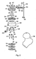
- Figures 1 and 2 relate to a first embodiment of guide wire location means of the invention and will be described in relation to the method of operation, whilst Figures 3 and 4 show a second embodiment of the guide wire location means and will be described by way of a second method of operation.
- the guide wire location means 10 comprises a base part which includes three identical circular plates 11, 12, 13 respectively, each plate having a central circular hole and, in the annular surface therearound, three equi-angularly spaced smaller circular threaded holes 14, 15, 16 respectively.
- the three plates are placed together with the three larger holes aligned and additionally with each of the smaller holes aligned with one of the smaller holes in the other of the two plates.
- the base part also includes three headed studs 17, 18, 19 respectively which have pointed ends remote from their respective heads, the respective bodies of the studs extending from the heads having a fine thread therealong. These studs are screwed into the respective aligned holes in the three plates 11, 12, 13 as shown for stud 17 in Figure 1 with its point extending below the lowermost plate 13.
- An enclosure 20 has a cylindrical lower portion 21 and a part-spherical upper portion 22, the upper portion having a central circular opening 23 therethrough.
- the wall thickness of the enclosure 20 is slightly greater with the lower portion 21 than the upper portion 22, but at its open end the interior of the lower portion 21 is outwardly stepped to provide an annular groove so that the assembly of the three plates 11, 12, and 13 can be located inside this open end of the cylindrical lower portion 21, as shown in Figure 1.
- a short, internally threaded boss 24 for receiving a locking screw 25.
- an adjustment member 26 Received within the enclosure 20 is an adjustment member 26 which has a generally cylindrical lower part 27 with a part spherical upper surface 28 which substantially matches the interior part-spherical surface of the portion 22 of the enclosure 20. From the centre of this upper surface 28 extends a hollow cylindrical boss 29 which projects through the opening 23 at the top of the enclosure 20 with clearance, in order to allow spherical adjustment motion of the adjustment member 26 within the enclosure 20.
- Three equi-angularly spaced slots are formed in the lower part 27 of adjustment member 26, these slots extending partly through the upper surface 28. Two of these slots 30, 31 are shown in Figure 2.
- a circular lock ring 32 On the upper part of the part-spherical exterior surface of the enclosure 20 is a circular lock ring 32.
- This has an exteriorly knurled outer cylindrical part 33, from which extends inwardly a domed portion 34 having a lower, part-spherical undersurface 35 which matches the part-spherical exterior surface at the top of the portion 22 of the enclosure 20.
- This portion 34 has a central circular hole 36 therein in which the boss 29 is a close fit, with external screw threads on this boss engaging with internal screw threads in the hole 36 so that the lock ring 32 can be screwed to the boss 29, and thus to the adjustment member 26 so as to draw the part-cylindrical surfaces of the member 26 and the lock ring 32 against the cooperating inner and outer part-spherical surfaces respectively of the adjustment member 26 as shown in Figure 1.
- the three studs 17 to 19 are received respectively in the three slots in the bottom of the adjustment member 26 with clearance, to allow articulation, but preventing rotation while tightening the lock ring 32.
- the boss 29 extends through the hole 36 of the portion 34 of the lock ring 32 and has received therein a cannula guide 37 which is the form of an elongated cylindrical body having an external circular flange 39 perpendicular thereto adjacent a reduced diameter end of the body.
- a fine circular bore 40 extends through the cannula guide 37 for the insertion of the guide wire for a drill (not shown) mentioned above.
- the flange 39 rests on the top of the boss 29 with the reduced diameter lower part of the cannula guide being received in the interior of the boss with significant clearance so that the planar position of the cannula guide can be readily adjusted.
- the cannula guide can be locked in position by a further circular lock ring 41 which, like the lock ring 32 has a knurled exterior surface.
- the further lock ring 41 is generally hollow and has its lower end open, with its exterior surface at said lower open end being externally threaded to engage with complimentary internal threads on the part 33 of the lock ring 32.
- the underside of an annular top flange 42 of the further circular lock ring 41 engages against the upper surface of the flange 39 to hold the cannula guide 37 in its adjusted position by virtue of it being forced tightly against the top of the boss 29.
- the centre of the flange 42 of the further lock ring 41 is provided with a central circular bore, this extending upwardly through an outwardly lipped boss 44, the annular lip 45 being spaced from, but extending parallel to, the top flange 42 of the further lock ring 41.
- a sighting disc 47 Fitted on top of the lip 45 with the body 38 of the cannula guide 37 extending closely through a central circular hole thereof is a sighting disc 47. This thus defines between itself and the upper surface of the flange 42 a stepped annular slot 48.
- the sighting disc 47 is the same size as the cylindrical saw cutter that will machine the femoral head.
- a slider 49 Inserted into this slot is a slider 49 which has an inner portion 50, of the same curvature as the boss 44 and lip 45, and from which extends a pair of spaced parallel arms 51, 52 respectively.
- the respective interior surfaces of the portion 50 and the arms 51, 52 are configurated to match the shape of the stepped slot, and the spacing of the arms is such that they engage diametrically opposed surfaces respectively of the lipped boss 44 so that the slider can be rotated around the boss.
- an extension part 53 of the slider at the opposite side of the portion 50 from that at which the arms extend is provided with a through hole in which is slidably adjustable rod-like XY probe 54 which with the disc 47 constitutes sighting means of the device.
- the probe At its lower end the probe is formed with a generally semi-circular contact member 55 arranged to engage the exterior surface of the head of a patient's femur 56.
- the probe in conjunction with the sighting disc 47, enable the Surgeon to gauge where the saw cutter will pass when it moves along the axis that the guide wire defines.
- the guide wire location means described above is used as follows.
- the Surgeon rests the base part, comprising the three plates 11 to 13 and the three studs 17 to 19, on the head of the femur as shown in Figure 1, the three plates being engaged together and the three studs each being screwed into one of the three series of three aligned holes in the plates respectively.
- this positioning of the base part on the head of the femur is such that it lies approximately on the chosen axis of the neck of the femur.
- a cylindrical drift tool (not shown) is then located into the central aligned larger holes of the plates of the base part and is used to drive the assembly of the plates and the studs into the surface of the bone of the femoral head, thereby securing it in position.
- the enclosure 20, adjustment member 26 and lock ring 32 are then fitted as an assembly, with the enclosure being fitted to the base part and secured by the locking screw 25 as shown in Figure 1, the three plates 11 to 13 which are engaged together, being received in the outwardly-stepped groove at the interior of the lower end of the enclosure 20.
- the lock ring 32 when unscrewed relative to the adjustment member 26, will allow spherical motion of the adjustment member 26 and lock ring 32 relative to the enclosure which is fast with the base part.
- the Surgeon can choose the correct angular position of the jig, prior to fitting the cannula guide 37.
- the surgeon can fit a protractor and probe device (not shown) into the bore in the boss 29 of the adjustment member and resting on its top surface. This can be used to provide correct angular alignment in both planes using pre-selected features on the femur.
- the Surgeon tightens the lock ring 32, with the result that the adjustment member 26 can no longer articulate.
- the three slots in the adjustment member 26, in which are received the studs 17 to 19 respectively prevent the adjustment member 26 from rotating about the centre line of the jig during tightening, but still allow articulation of the adjustment member 26 relative to the enclosure.
- the Surgeon then fits the cannula guide 37, the further lock ring 41 and the sighting disc 47 as shown in Figure 1.
- the sighting disc is the same size as the hollow cylindrical saw cutter and thus represents the final machine diameter of the femoral head prior to the fitting of the resurfacing device.
- the Surgeon then slides the slider 49 and the XY probe 54 into position so that the contact member 55 touches the high point of the head of the femur, as shown in Figure 1.
- the Surgeon is thus able visually to judge the position of the sighting disc/cannula guide relative to a sighting mark on the top surface of the slider.
- the Surgeon would probe the head of femur at various heights depending on the shap and degree of malformation - each time comparing the resting position of the probe against the head/neck of the femur with the sighting disc 47 (representing the cylindrical saw cutter that would subsequently be used). In this way he is able to predict where material would be removed and where there would be clearance from the cutter. Thus he can decide if adjustment of the guide 37 is required.
- the surgeon fixes its position by screwing up the further lock wing 41 so that the arrangement shown in Figure 1 is reached with the cannula guide held in position between the flange 42 and the top of the boss 29.
- the insertion of the guide wire using the central hole in the cannula guide as a location can then proceed, with this now being set very accurately so that subsequently the drilling of the femur head is similarly of improved accuracy arid is thus at the chosen axis previously identified by the Surgeon through analysis of X-ray or similar technique.
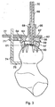
- the adjustable base part of the first embodiment is replaced with a one-piece base part 57 in the form of an annulus having an exterior cylindrical surface 58 and a part-spherical upper surface 59.
- Spikes 60 extend from the underside of the surface 58 to be equivalent to the points provided by the studs 17 to 19 of the first embodiment.
- the annulus defines a central circular opening 61 and the interior surface of this opening can be slightly tapered as shown in Figure 3.
- This base part 57 will be manufactured in such a manner as to allow the insertion of a Ferro-magnetic core, contained within a Medical Stainless Steel exterior.
- an adjustment member 62 Received in engagement with the part 57 on the upper part-spherical surface 59 thereof is an adjustment member 62 which is effectively equivalent to the assembly of the first embodiment formed by the enclosure 20, the adjustment member 26 and the lock ring 32.
- This adjustment member 62 is basically in the form of a circular annulus having a central circular opening 63 therethrough.
- the member 62 has its lower surface 64 of part spherical form to match the part-spherical upper surface 59 of the base part 57 to allow spherical adjustment motion as with the first embodiment.
- the external cylindrical surface of the annular adjustment member 62 is formed with a rectangular annular groove 65.
- the adjustment member 62 will, like the base part 57, be manufactured in such a manner as to allow the insertion of magnetic material into a Medical Stainless Steel exterior. Accordingly when placed onto the base part 57, the adjustment member 62 will magnetically adhere to the part-spherical surface thereof as shown in Figure 3.
- a cannula guide 66 of this second embodiment is of similar form to cannula guide 37 of the first embodiment, but does not have its body continuing below the circular exterior flange which in Figures 3 and 4 is denoted by the numeral 67. Moreover the bore 68 through the guide 66, is no longer fine but is widened to receive an elongated pivot rod 69 therethrough, the rod 69 having a fine bore 70 therethrough for the insertion of the guide wire .
- the lower end of the pivot rod 69 which extends below flange 67, is barbed or similarly configured so that it can be pushed into the surface of the bone of the femur head to provide additional support as shown in Figure 3.
- the cannula guide will be manufactured in such a manner so as to allow the insertion of a Ferro-magnetic core, contained within a Medical Stainless Steel exterior.
- the cannula guide will magnetically adhere to the planar surface thereon as shown in Figure 3, with the opening 63 in the member 62 and the opening 61 in the part 57 being greatly oversized relative to the diameter of the pivot rod so as to allow for planar adjustment, as with the first embodiment, of the cannula guide, and thus the pivot rod.
- a slider 71 of similar form to the slider 49 of the first embodiment has its arms 72, 73 respectively received in and above the groove 65 formed in the adjustment member 62 so that diametrically opposed inner surfaces of the groove 65 engage respective interior surfaces of a lower part of each of the arms.
- An XY probe 74 is slidably adjustably received through an opening in an extension part 75 of the slider, this probe 74 having at its lower end a semi-circular contact member 76 to engage the femur as shown in Figure 3.
- this embodiment includes, like the first embodiment, a sighting disc 77
- this disc is, in this embodiment, received on the end of the circular rod of the probe 74 as shown in Figure 3, so that it lies on the extension part 75 and extends to the top of the adjustment member 62 so that, as shown in Figure 3, it can be in abutting relationship with the outer surface of the flange 67.
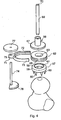
- this second embodiment functions in the following manner.
- the one-piece base part 57 is placed on the femoral head so that it lies approximately on the chosen axis.
- the base part 57 will have at least two or more fixed spikes or studs, with a profile that allows sufficient anchorage into the bone, without having an adverse effect on the fixation of the prosthesis.
- the application and removal of the base part will be by means of a separate drift tool (not shown).
- the adjustment member 62 is placed on the top surface thereof, and magnetically adheres thereto as mentioned above. The Surgeon will position the adjustment member 62 to provide appropriate angular position.
- the spherically adjusted angular position of the adjustment member can be tested with a protractor device (not shown) inserted into the opening 63 of the adjustment member 62.
- a protractor device not shown
- the cannula guide 66 will be placed onto the upper surface of the adjustment member 62, as shown in Figure 3, and the cannula guide will thus magnetically adhere to the upper planar surface of the adjustment member 62.
- the Surgeon then applies the slider 71 and probe 74 at the groove 65 to determine the optimum position of the cannula guide in one plane.
- the sighting disc 77 is applied to the probe 74 as shown in Figure 3.
- Alternative sizes of sighting disc 77 can be used depending on the size of prosthesis to be fitted.
- the contact member 76 is at a lower part of the femoral head as compared with its position as shown in Figure 1 in the previous embodiment, although this is not a significant difference in that the probe will be used on various points of the head, and/or the neck, of the femur.
- the slider can be rotated in its groove 65 in order to make similar adjustments in alternative planes.
- the sighting disc and probe can be used to determine if any incremental adjustment of the guide 66 is required.
- the pivot rod 69 is inserted into the bore 68 of the cannula guide and pushed down into the surface of the bone to provide additional support as described above. It is then possible to proceed accurately with the insertion of the guide wire through the fine bore 70 in the pivot rod.
Landscapes
- Health & Medical Sciences (AREA)
- Surgery (AREA)
- Life Sciences & Earth Sciences (AREA)
- Medical Informatics (AREA)
- Animal Behavior & Ethology (AREA)
- Orthopedic Medicine & Surgery (AREA)
- Oral & Maxillofacial Surgery (AREA)
- Engineering & Computer Science (AREA)
- Biomedical Technology (AREA)
- Heart & Thoracic Surgery (AREA)
- Dentistry (AREA)
- Molecular Biology (AREA)
- Nuclear Medicine, Radiotherapy & Molecular Imaging (AREA)
- General Health & Medical Sciences (AREA)
- Public Health (AREA)
- Veterinary Medicine (AREA)
- Surgical Instruments (AREA)
- Prostheses (AREA)
- Media Introduction/Drainage Providing Device (AREA)
- Powder Metallurgy (AREA)
- Fats And Perfumes (AREA)
Claims (30)
- Ein Lokalisierungsmittel (10) für einen Führungsdraht zum Lokalisieren, im Gebrauch, eines Führungsdrahts an einer Achse eines Oberschenkelhalses eines Patienten, das Folgendes beinhaltet:einen Basisteil zur Sicherung an einen Oberschenkelkopf;einen Teil, der an dem Basisteil gesichert werden kann,einen Teil zur direkten oder indirekten Aufnahme einer Drahtführung und der zur planaren Einstellung angeordnet ist und ein Sichtmittel, das eine Sonde (54) mit einem Teil, der mit dem Oberschenkelkopf und/oder -hals im Eingriff stehen kann, umfasst, dadurch gekennzeichnet, dass der Teil, der an dem Basisteil gesichert werden kann, relativ dazu sphärisch eingestellt werden kann; und wobei der Drahtführungsaufnahmeteil an dem Teil, der sphärisch eingestellt werden kann, gesichert werden kann.
- Lokalisierungsmittel (10) für einen Führungsdraht gemäß Anspruch 1, bei dem das Sichtmittel einen Sichtbestandteil umfasst.
- Lokalisierungsmittel (10) für einen Führungsdraht gemäß Anspruch 2, bei dem der Sichtbestandteil eine Scheibe (47) ist.
- Lokalisierungsmittel (10) für einen Führungsdraht gemäß Anspruch 3, bei dem die Scheibe (47) die gleiche Größe wie das Innere eines zylindrischen Sägemessers, das den Kopf bearbeiten wird, aufweist.
- Lokalisierungsmittel (10) für einen Führungsdraht gemäß Anspruch 1, bei dem der Basisteil identische, runde Platten (11, 12, 13) umfasst.
- Lokalisierungsmittel (10) für einen Führungsdraht gemäß Anspruch 5, bei dem die identischen, runden Platten eine zentrale Öffnung aufweisen.
- Lokalisierungsmittel (10) für einen Führungsdraht gemäß Anspruch 6, bei dem die identischen, runden Platten dort um die zentrale Öffnung herum in ihren ringförmigen Oberflächen gleichwinklig mit Abstand angeordnete Öffnungen (14, 15, 16) aufweisen.
- Lokalisierungsmittel (10) für einen Führungsdraht gemäß Anspruch 7, bei dem die gleichwinklig mit Abstand angeordneten Öffnungen (14,15,16) drei an der Zahl sind.
- Lokalisierungsmittel (10) für einen Führungsdraht gemäß Anspruch 7 oder 8, bei dem die gleichwinklig mit Abstand angeordneten Öffnungen (14,15,16) gewindet sind.
- Lokalisierungsmittel (10) für einen Führungsdraht gemäß einem der Ansprüche 1 bis 9, bei dem der Basisteil Bolzen (17, 18, 19) mit Kopf umfasst, die entfernt von ihren Köpfen zugespitzte Enden aufweisen.
- Lokalisierungsmittel (10) für einen Führungsdraht gemäß einem der Ansprüche 5 bis 9, das eine Einfassung (20) mit einem zylindrischen unteren Abschnitt (21) und einen teilweise sphärischen oberen Abschnitt (22) aufweist, wobei der obere Abschnitt einen zentralen Durchgang (23) aufweist.
- Lokalisierungsmittel (10) für einen Führungsdraht gemäß Anspruch 11, bei dem der zylindrische untere Abschnitt (21) der Einfassung (20) nach außen gestuft ist, um eine ringförmige Aussparung bereitzustellen, so dass die Anordnung der Platten (11, 12, 13) in diesem offenen Ende des zylindrischen unteren Abschnitts (21) lokalisiert sein kann.
- Lokalisierungsmittel (10) für einen Führungsdraht gemäß Anspruch 12, bei dem ein Einstellelement (26) so geformt ist, dass es innerhalb der Einfassung (20) aufgenommen werden kann.
- Lokalisierungsmittel (10) für einen Führungsdraht gemäß Anspruch 13, bei dem das Einstellelement einen im Allgemeinen zylindrischen unteren Teil (27) mit einer teilweise sphärischen oberen Oberfläche (28) aufweist, die im Wesentlichen der teilweise sphärischen Oberfläche im Inneren des Abschnitts (22) der Einfassung (20) entspricht.
- Lokalisierungsmittel (10) für einen Führungsdraht gemäß Anspruch 14, bei dem das Einstellelement (26) von dem Zentrum seiner oberen Oberfläche (28) eine hohle, zylindrische Nabe (29), die durch den Durchgang (23) an dem oberen Ende der Einfassung (20) hervorsteht, aufweist.
- Lokalisierungsmittel (10) für einen Führungsdraht gemäß einem der Ansprüche 14 oder 15, bei dem der untere Teil (27) des Einstellelements (26) gleichwinklig mit Abstand angeordnete Schlitze aufweist, wobei sich diese Schlitze teilweise durch die obere Oberfläche (28) erstrecken.
- Lokalisierungsmittel (10) für einen Führungsdraht gemäß Anspruch 16, bei dem drei gleichwinklig mit Abstand angeordnete Schlitze vorhanden sind.
- Lokalisierungsmittel (10) für einen Führungsdraht gemäß einem der Ansprüche 11 bis 17, bei dem ein runder Verschlussring (32) entfernbar an dem oberen Teil der teilweise sphärischen, äußeren Oberfläche der Einfassung (20) befestigt werden kann.
- Lokalisierungsmittel (10) für einen Führungsdraht gemäß einem der Ansprüche 15, 16 oder 17, bei dem eine Kanülenführung (37) so geformt und konfiguriert ist, dass sie von der Nabe (29) aufgenommen wird.
- Lokalisierungsmittel (10) für einen Führungsdraht gemäß Anspruch 15 oder einem der Ansprüche 16 oder 17, wenn abhängig von Anspruch 15, bei dem eine Kanülenführung so geformt und konfiguriert ist, dass sie von der Nabe aufgenommen wird, wenn sich die Nabe (29) durch ein Loch (36) des Verschlussrings (32) erstreckt.
- Lokalisierungsmittel (10) für einen Führungsdraht gemäß Anspruch 19 oder 20, bei dem die Kanülenführung (37) als ein verlängerter, zylindrischer Körper mit einem äußeren, runden, dazu rechtwinkligen Flansch (39), der an ein Ende des Körpers mit verringertem Durchmesser angrenzt, aufweist.
- Lokalisierungsmittel (10) für einen Führungsdraht gemäß einem der Ansprüche 19, 20 oder 21, bei dem sich eine Sichtscheibe eng durch eine zentrale runde Öffnung des Körpers (38) der Kanülenführung (37) erstreckt.
- Lokalisierungsmittel (10) für einen Führungsdraht gemäß einem der Ansprüche 1 bis 4, bei dem der Basisteil zur Sicherung an einem Oberschenkelkopf ein einteiliger Basisteil (57) ist.
- Lokalisierungsmittel (10) für einen Führungsdraht gemäß Anspruch 23, bei dem der einteilige Basisteil (57) als ein Kranz mit einer äußeren, zylindrischen Oberfläche (58) und einer teilweise sphärischen oberen Oberfläche (59) gebildet ist.
- Lokalisierungsmittel (10) für einen Führungsdraht gemäß Anspruch 23 oder 24, bei dem sich Spitzen (60) von der Unterseite der Oberfläche (58) erstrecken.
- Lokalisierungsmittel (10) für einen Führungsdraht gemäß einem der Ansprüche 1, 2, 3 oder 23 bis 25, bei dem sich eine Sichtscheibe (77) zu dem oberen Ende eines Einstellelement erstreckt.
- Lokalisierungsmittel (10) für einen Führungsdraht gemäß Anspruch 26, bei dem dle Sichtscheibe (77) an dem Ende eines runden Stabs einer Sonde (74) aufgenommen wird, wobei die Sonde (74) an ihrem unteren Ende zum Eingriff mit dem Oberschenkelknochen ein Kontaktelement (76) aufweist.
- Lokalisierungsmittel (10) für einen Führungsdraht gemäß den Ansprüchen 13 bis 17 oder 26, bei dem das Einstellelement (62) in derartiger Weise hergestellt werden kann, um die Einführung eines magnetischen Materials zu erlauben.
- Lokalisierungsmittel (10) für einen Führungsdraht gemäß einem der vorhergehenden Ansprüche, bei dem der Basisteil in derartiger Weise hergestellt werden kann, um die Einführung eines magnetischen Materials zu erlauben.
- Lokalisierungsmittel (10) für einen Führungsdraht gemäß einem der vorhergehenden Ansprüche, das ein magnetisches Material beinhaltet.
Applications Claiming Priority (2)
| Application Number | Priority Date | Filing Date | Title |
|---|---|---|---|
| GBGB0313445.9A GB0313445D0 (en) | 2003-06-11 | 2003-06-11 | Hip resurfacing |
| PCT/GB2004/002531 WO2004107993A1 (en) | 2003-06-11 | 2004-06-11 | Guide wire location means for the insertion of a prostetic hip resurfacing |
Publications (2)
| Publication Number | Publication Date |
|---|---|
| EP1631202A1 EP1631202A1 (de) | 2006-03-08 |
| EP1631202B1 true EP1631202B1 (de) | 2007-03-07 |
Family
ID=27589852
Family Applications (1)
| Application Number | Title | Priority Date | Filing Date |
|---|---|---|---|
| EP04736659A Expired - Lifetime EP1631202B1 (de) | 2003-06-11 | 2004-06-11 | Vorrichtung zur positionierung eines führungsdrahtes für die einführung einer hüftgelenkkopfprothese |
Country Status (11)
| Country | Link |
|---|---|
| US (1) | US20060271058A1 (de) |
| EP (1) | EP1631202B1 (de) |
| JP (1) | JP4593564B2 (de) |
| AT (1) | ATE355791T1 (de) |
| AU (1) | AU2004244819B2 (de) |
| CA (1) | CA2528699C (de) |
| DE (1) | DE602004005186T2 (de) |
| ES (1) | ES2284017T3 (de) |
| GB (1) | GB0313445D0 (de) |
| TW (1) | TWI342200B (de) |
| WO (1) | WO2004107993A1 (de) |
Families Citing this family (117)
| Publication number | Priority date | Publication date | Assignee | Title |
|---|---|---|---|---|
| US8801720B2 (en) | 2002-05-15 | 2014-08-12 | Otismed Corporation | Total joint arthroplasty system |
| GB0322084D0 (en) * | 2003-09-22 | 2003-10-22 | Depuy Int Ltd | A drill guide assembly |
| DE602005014018D1 (de) * | 2004-04-20 | 2009-05-28 | Finsbury Dev Ltd | Ausrichtungsführung |
| EP1588668B1 (de) * | 2004-04-20 | 2008-12-10 | Finsbury (Development) Limited | Zielgerät zur Operationen des Femurkopfs |
| US20060025775A1 (en) * | 2004-07-28 | 2006-02-02 | Howmedica Osteonics Corp. | Femoral neck resection guide and method |
| GB0505782D0 (en) * | 2005-03-22 | 2005-04-27 | Depuy Int Ltd | Surgical guide |
| EP1890601A4 (de) * | 2005-06-17 | 2015-04-22 | Orthosoft Inc | Verfahren und vorrichtung für die computergestützte oberflächenbearbeitung des femurkopfs |
| US7846164B2 (en) * | 2005-06-18 | 2010-12-07 | Ortho Impact Corporation | Pedicle punch with cannula |
| EP1772106A1 (de) * | 2005-10-06 | 2007-04-11 | Zimmer GmbH | Instrument zum Vorbereiten und/oder Bearbeiten eines Femurkopfes |
| GB0521173D0 (en) * | 2005-10-18 | 2005-11-23 | Finsbury Dev Ltd | Tool |
| GB0525637D0 (en) * | 2005-12-16 | 2006-01-25 | Finsbury Dev Ltd | Tool |
| US9808262B2 (en) | 2006-02-15 | 2017-11-07 | Howmedica Osteonics Corporation | Arthroplasty devices and related methods |
| CA2642615A1 (en) | 2006-02-15 | 2007-08-30 | Otismed Corp | Arthroplasty jigs and related methods |
| US8241293B2 (en) | 2006-02-27 | 2012-08-14 | Biomet Manufacturing Corp. | Patient specific high tibia osteotomy |
| US8133234B2 (en) | 2006-02-27 | 2012-03-13 | Biomet Manufacturing Corp. | Patient specific acetabular guide and method |
| US8535387B2 (en) | 2006-02-27 | 2013-09-17 | Biomet Manufacturing, Llc | Patient-specific tools and implants |
| US7967868B2 (en) | 2007-04-17 | 2011-06-28 | Biomet Manufacturing Corp. | Patient-modified implant and associated method |
| US8603180B2 (en) | 2006-02-27 | 2013-12-10 | Biomet Manufacturing, Llc | Patient-specific acetabular alignment guides |
| US8858561B2 (en) | 2006-06-09 | 2014-10-14 | Blomet Manufacturing, LLC | Patient-specific alignment guide |
| US8377066B2 (en) | 2006-02-27 | 2013-02-19 | Biomet Manufacturing Corp. | Patient-specific elbow guides and associated methods |
| US9345548B2 (en) | 2006-02-27 | 2016-05-24 | Biomet Manufacturing, Llc | Patient-specific pre-operative planning |
| US8608749B2 (en) | 2006-02-27 | 2013-12-17 | Biomet Manufacturing, Llc | Patient-specific acetabular guides and associated instruments |
| US10278711B2 (en) | 2006-02-27 | 2019-05-07 | Biomet Manufacturing, Llc | Patient-specific femoral guide |
| US8407067B2 (en) | 2007-04-17 | 2013-03-26 | Biomet Manufacturing Corp. | Method and apparatus for manufacturing an implant |
| US8591516B2 (en) | 2006-02-27 | 2013-11-26 | Biomet Manufacturing, Llc | Patient-specific orthopedic instruments |
| US8608748B2 (en) | 2006-02-27 | 2013-12-17 | Biomet Manufacturing, Llc | Patient specific guides |
| US9918740B2 (en) | 2006-02-27 | 2018-03-20 | Biomet Manufacturing, Llc | Backup surgical instrument system and method |
| US9113971B2 (en) | 2006-02-27 | 2015-08-25 | Biomet Manufacturing, Llc | Femoral acetabular impingement guide |
| US8473305B2 (en) | 2007-04-17 | 2013-06-25 | Biomet Manufacturing Corp. | Method and apparatus for manufacturing an implant |
| US8864769B2 (en) | 2006-02-27 | 2014-10-21 | Biomet Manufacturing, Llc | Alignment guides with patient-specific anchoring elements |
| US9907659B2 (en) | 2007-04-17 | 2018-03-06 | Biomet Manufacturing, Llc | Method and apparatus for manufacturing an implant |
| US9173661B2 (en) | 2006-02-27 | 2015-11-03 | Biomet Manufacturing, Llc | Patient specific alignment guide with cutting surface and laser indicator |
| US20150335438A1 (en) | 2006-02-27 | 2015-11-26 | Biomet Manufacturing, Llc. | Patient-specific augments |
| US8568487B2 (en) | 2006-02-27 | 2013-10-29 | Biomet Manufacturing, Llc | Patient-specific hip joint devices |
| US8282646B2 (en) | 2006-02-27 | 2012-10-09 | Biomet Manufacturing Corp. | Patient specific knee alignment guide and associated method |
| US9339278B2 (en) | 2006-02-27 | 2016-05-17 | Biomet Manufacturing, Llc | Patient-specific acetabular guides and associated instruments |
| US9289253B2 (en) | 2006-02-27 | 2016-03-22 | Biomet Manufacturing, Llc | Patient-specific shoulder guide |
| US8070752B2 (en) | 2006-02-27 | 2011-12-06 | Biomet Manufacturing Corp. | Patient specific alignment guide and inter-operative adjustment |
| US8092465B2 (en) | 2006-06-09 | 2012-01-10 | Biomet Manufacturing Corp. | Patient specific knee alignment guide and associated method |
| US8298237B2 (en) | 2006-06-09 | 2012-10-30 | Biomet Manufacturing Corp. | Patient-specific alignment guide for multiple incisions |
| US9795399B2 (en) | 2006-06-09 | 2017-10-24 | Biomet Manufacturing, Llc | Patient-specific knee alignment guide and associated method |
| US8021369B2 (en) * | 2006-06-12 | 2011-09-20 | Howmedica Osteonics Corp. | Navigated femoral neck resection guide and method |
| GB0614428D0 (en) * | 2006-07-20 | 2006-08-30 | Smith & Nephew | Medical device |
| WO2008014618A1 (en) * | 2006-08-03 | 2008-02-07 | Orthosoft Inc. | Computer-assisted surgery tools and system |
| FR2906452B1 (fr) * | 2006-10-02 | 2008-12-05 | Tornier Sas | Ancillaire de visee pour resurfacage de la tete femorale |
| GB2442441B (en) | 2006-10-03 | 2011-11-09 | Biomet Uk Ltd | Surgical instrument |
| US20080109085A1 (en) | 2006-11-03 | 2008-05-08 | Howmedica Osteonics Corp. | Method and apparatus for hip femoral resurfacing tooling |
| US8460302B2 (en) | 2006-12-18 | 2013-06-11 | Otismed Corporation | Arthroplasty devices and related methods |
| CA2692889A1 (en) * | 2007-07-11 | 2009-01-15 | Robert J. Daley | Methods and apparatus for determining pin placement during hip surgery |
| US8265949B2 (en) | 2007-09-27 | 2012-09-11 | Depuy Products, Inc. | Customized patient surgical plan |
| US8398645B2 (en) | 2007-09-30 | 2013-03-19 | DePuy Synthes Products, LLC | Femoral tibial customized patient-specific orthopaedic surgical instrumentation |
| US8357111B2 (en) | 2007-09-30 | 2013-01-22 | Depuy Products, Inc. | Method and system for designing patient-specific orthopaedic surgical instruments |
| US8460303B2 (en) | 2007-10-25 | 2013-06-11 | Otismed Corporation | Arthroplasty systems and devices, and related methods |
| USD642263S1 (en) | 2007-10-25 | 2011-07-26 | Otismed Corporation | Arthroplasty jig blank |
| US10582934B2 (en) | 2007-11-27 | 2020-03-10 | Howmedica Osteonics Corporation | Generating MRI images usable for the creation of 3D bone models employed to make customized arthroplasty jigs |
| US8160345B2 (en) | 2008-04-30 | 2012-04-17 | Otismed Corporation | System and method for image segmentation in generating computer models of a joint to undergo arthroplasty |
| US8545509B2 (en) | 2007-12-18 | 2013-10-01 | Otismed Corporation | Arthroplasty system and related methods |
| US8777875B2 (en) | 2008-07-23 | 2014-07-15 | Otismed Corporation | System and method for manufacturing arthroplasty jigs having improved mating accuracy |
| US8737700B2 (en) | 2007-12-18 | 2014-05-27 | Otismed Corporation | Preoperatively planning an arthroplasty procedure and generating a corresponding patient specific arthroplasty resection guide |
| US8480679B2 (en) | 2008-04-29 | 2013-07-09 | Otismed Corporation | Generation of a computerized bone model representative of a pre-degenerated state and useable in the design and manufacture of arthroplasty devices |
| US8221430B2 (en) | 2007-12-18 | 2012-07-17 | Otismed Corporation | System and method for manufacturing arthroplasty jigs |
| US8311306B2 (en) | 2008-04-30 | 2012-11-13 | Otismed Corporation | System and method for image segmentation in generating computer models of a joint to undergo arthroplasty |
| US8715291B2 (en) | 2007-12-18 | 2014-05-06 | Otismed Corporation | Arthroplasty system and related methods |
| US8617171B2 (en) | 2007-12-18 | 2013-12-31 | Otismed Corporation | Preoperatively planning an arthroplasty procedure and generating a corresponding patient specific arthroplasty resection guide |
| US8734455B2 (en) | 2008-02-29 | 2014-05-27 | Otismed Corporation | Hip resurfacing surgical guide tool |
| US8617175B2 (en) | 2008-12-16 | 2013-12-31 | Otismed Corporation | Unicompartmental customized arthroplasty cutting jigs and methods of making the same |
| GB0823298D0 (en) | 2008-12-22 | 2009-01-28 | Depuy Int Ltd | Surgical jig |
| US8170641B2 (en) | 2009-02-20 | 2012-05-01 | Biomet Manufacturing Corp. | Method of imaging an extremity of a patient |
| DE102009028503B4 (de) | 2009-08-13 | 2013-11-14 | Biomet Manufacturing Corp. | Resektionsschablone zur Resektion von Knochen, Verfahren zur Herstellung einer solchen Resektionsschablone und Operationsset zur Durchführung von Kniegelenk-Operationen |
| US8632547B2 (en) | 2010-02-26 | 2014-01-21 | Biomet Sports Medicine, Llc | Patient-specific osteotomy devices and methods |
| US9066727B2 (en) | 2010-03-04 | 2015-06-30 | Materialise Nv | Patient-specific computed tomography guides |
| TWI413509B (zh) * | 2010-09-24 | 2013-11-01 | Alliance Global Technology Co Ltd | Guide structure |
| US9271744B2 (en) | 2010-09-29 | 2016-03-01 | Biomet Manufacturing, Llc | Patient-specific guide for partial acetabular socket replacement |
| US9968376B2 (en) | 2010-11-29 | 2018-05-15 | Biomet Manufacturing, Llc | Patient-specific orthopedic instruments |
| US9241745B2 (en) | 2011-03-07 | 2016-01-26 | Biomet Manufacturing, Llc | Patient-specific femoral version guide |
| US8715289B2 (en) | 2011-04-15 | 2014-05-06 | Biomet Manufacturing, Llc | Patient-specific numerically controlled instrument |
| US9675400B2 (en) | 2011-04-19 | 2017-06-13 | Biomet Manufacturing, Llc | Patient-specific fracture fixation instrumentation and method |
| US8956364B2 (en) | 2011-04-29 | 2015-02-17 | Biomet Manufacturing, Llc | Patient-specific partial knee guides and other instruments |
| US8668700B2 (en) | 2011-04-29 | 2014-03-11 | Biomet Manufacturing, Llc | Patient-specific convertible guides |
| US8532807B2 (en) | 2011-06-06 | 2013-09-10 | Biomet Manufacturing, Llc | Pre-operative planning and manufacturing method for orthopedic procedure |
| US9084618B2 (en) | 2011-06-13 | 2015-07-21 | Biomet Manufacturing, Llc | Drill guides for confirming alignment of patient-specific alignment guides |
| US20130001121A1 (en) | 2011-07-01 | 2013-01-03 | Biomet Manufacturing Corp. | Backup kit for a patient-specific arthroplasty kit assembly |
| US8764760B2 (en) | 2011-07-01 | 2014-07-01 | Biomet Manufacturing, Llc | Patient-specific bone-cutting guidance instruments and methods |
| US8597365B2 (en) | 2011-08-04 | 2013-12-03 | Biomet Manufacturing, Llc | Patient-specific pelvic implants for acetabular reconstruction |
| US9295497B2 (en) | 2011-08-31 | 2016-03-29 | Biomet Manufacturing, Llc | Patient-specific sacroiliac and pedicle guides |
| US9066734B2 (en) | 2011-08-31 | 2015-06-30 | Biomet Manufacturing, Llc | Patient-specific sacroiliac guides and associated methods |
| US9386993B2 (en) | 2011-09-29 | 2016-07-12 | Biomet Manufacturing, Llc | Patient-specific femoroacetabular impingement instruments and methods |
| US9554910B2 (en) | 2011-10-27 | 2017-01-31 | Biomet Manufacturing, Llc | Patient-specific glenoid guide and implants |
| US9301812B2 (en) | 2011-10-27 | 2016-04-05 | Biomet Manufacturing, Llc | Methods for patient-specific shoulder arthroplasty |
| KR20130046337A (ko) | 2011-10-27 | 2013-05-07 | 삼성전자주식회사 | 멀티뷰 디바이스 및 그 제어방법과, 디스플레이장치 및 그 제어방법과, 디스플레이 시스템 |
| US9451973B2 (en) | 2011-10-27 | 2016-09-27 | Biomet Manufacturing, Llc | Patient specific glenoid guide |
| WO2013062848A1 (en) | 2011-10-27 | 2013-05-02 | Biomet Manufacturing Corporation | Patient-specific glenoid guides |
| US9237950B2 (en) | 2012-02-02 | 2016-01-19 | Biomet Manufacturing, Llc | Implant with patient-specific porous structure |
| US9402637B2 (en) | 2012-10-11 | 2016-08-02 | Howmedica Osteonics Corporation | Customized arthroplasty cutting guides and surgical methods using the same |
| US9060788B2 (en) | 2012-12-11 | 2015-06-23 | Biomet Manufacturing, Llc | Patient-specific acetabular guide for anterior approach |
| US9204977B2 (en) | 2012-12-11 | 2015-12-08 | Biomet Manufacturing, Llc | Patient-specific acetabular guide for anterior approach |
| US9839438B2 (en) | 2013-03-11 | 2017-12-12 | Biomet Manufacturing, Llc | Patient-specific glenoid guide with a reusable guide holder |
| US9579107B2 (en) | 2013-03-12 | 2017-02-28 | Biomet Manufacturing, Llc | Multi-point fit for patient specific guide |
| US9826981B2 (en) | 2013-03-13 | 2017-11-28 | Biomet Manufacturing, Llc | Tangential fit of patient-specific guides |
| US9498233B2 (en) | 2013-03-13 | 2016-11-22 | Biomet Manufacturing, Llc. | Universal acetabular guide and associated hardware |
| US9517145B2 (en) | 2013-03-15 | 2016-12-13 | Biomet Manufacturing, Llc | Guide alignment system and method |
| WO2014175986A2 (en) | 2013-04-23 | 2014-10-30 | RevOrtho LLC | A method and system for modular hip resurfacing |
| US20150112349A1 (en) | 2013-10-21 | 2015-04-23 | Biomet Manufacturing, Llc | Ligament Guide Registration |
| US10282488B2 (en) | 2014-04-25 | 2019-05-07 | Biomet Manufacturing, Llc | HTO guide with optional guided ACL/PCL tunnels |
| US9408616B2 (en) | 2014-05-12 | 2016-08-09 | Biomet Manufacturing, Llc | Humeral cut guide |
| US9839436B2 (en) | 2014-06-03 | 2017-12-12 | Biomet Manufacturing, Llc | Patient-specific glenoid depth control |
| US9561040B2 (en) | 2014-06-03 | 2017-02-07 | Biomet Manufacturing, Llc | Patient-specific glenoid depth control |
| US9833245B2 (en) | 2014-09-29 | 2017-12-05 | Biomet Sports Medicine, Llc | Tibial tubercule osteotomy |
| US9826994B2 (en) | 2014-09-29 | 2017-11-28 | Biomet Manufacturing, Llc | Adjustable glenoid pin insertion guide |
| US9820868B2 (en) | 2015-03-30 | 2017-11-21 | Biomet Manufacturing, Llc | Method and apparatus for a pin apparatus |
| US10568647B2 (en) | 2015-06-25 | 2020-02-25 | Biomet Manufacturing, Llc | Patient-specific humeral guide designs |
| US10226262B2 (en) | 2015-06-25 | 2019-03-12 | Biomet Manufacturing, Llc | Patient-specific humeral guide designs |
| US11090161B2 (en) * | 2016-03-25 | 2021-08-17 | Howmedica Osteonics Corp. | Surgical instrumentation assembly, set and surgical shoulder repair method |
| US10722310B2 (en) | 2017-03-13 | 2020-07-28 | Zimmer Biomet CMF and Thoracic, LLC | Virtual surgery planning system and method |
| CN106821454A (zh) * | 2017-04-17 | 2017-06-13 | 北京大学第三医院 | 一种股骨截骨器械套件 |
| US11051829B2 (en) | 2018-06-26 | 2021-07-06 | DePuy Synthes Products, Inc. | Customized patient-specific orthopaedic surgical instrument |
| KR102125716B1 (ko) * | 2019-11-06 | 2020-06-23 | 의료법인 명지의료재단 | 삽입 각도 재현 가능한 k-강선 가이드 기구 |
Family Cites Families (13)
| Publication number | Priority date | Publication date | Assignee | Title |
|---|---|---|---|---|
| DE1164019B (de) * | 1960-03-29 | 1964-02-27 | Chiron Werke G M B H | Hueftgelenkkopfprothese und Bohrvorrichtung fuer ihre Befestigung |
| US4896663A (en) * | 1988-10-14 | 1990-01-30 | Boehringer Mannheim Corporation | Self centering femoral drill jig |
| US5364401A (en) * | 1992-10-08 | 1994-11-15 | Wright Medical Technology, Inc. | External alignment system for preparing a femur for an implant |
| SE9203579L (sv) * | 1992-11-26 | 1994-05-27 | Gustaf Gadelius | Sätt att bestämma ett lårbens läge i förhållande till ett bäckenben i samband med en höftledsoperation |
| CA2126627C (en) * | 1993-07-06 | 2005-01-25 | Kim C. Bertin | Femoral milling instrumentation for use in total knee arthroplasty with optional cutting guide attachment |
| WO1996018351A1 (en) * | 1994-12-16 | 1996-06-20 | Exactech, Inc. | An improved intramedullary alignment guide |
| EP0971638A4 (de) * | 1997-01-28 | 2003-07-30 | New York Society | Verfahren und vorrichtung zur femoral-resektion |
| ES2224406T3 (es) * | 1998-06-29 | 2005-03-01 | Plus Endoprothetik Ag | Dispositivo para insertar una protesis de rodilla. |
| US6156069A (en) * | 1999-02-04 | 2000-12-05 | Amstutz; Harlan C. | Precision hip joint replacement method |
| JP2000287983A (ja) * | 1999-04-07 | 2000-10-17 | Mizuho Co Ltd | 人工膝関節置換術用大腿骨髄外クランプガイド装置 |
| EP1252868B1 (de) * | 2001-04-27 | 2006-06-21 | Zimmer GmbH | Bohrlehere für die Festlegung der Achse einer Femurkopfprothese |
| CN2519658Y (zh) * | 2001-12-29 | 2002-11-06 | 上海复升医疗器械有限公司 | 安装股骨颈保护装置的器具 |
| US7527631B2 (en) * | 2003-03-31 | 2009-05-05 | Depuy Products, Inc. | Arthroplasty sizing gauge |
-
2003
- 2003-06-11 GB GBGB0313445.9A patent/GB0313445D0/en not_active Ceased
-
2004
- 2004-06-11 DE DE602004005186T patent/DE602004005186T2/de not_active Expired - Lifetime
- 2004-06-11 US US10/559,945 patent/US20060271058A1/en not_active Abandoned
- 2004-06-11 ES ES04736659T patent/ES2284017T3/es not_active Expired - Lifetime
- 2004-06-11 WO PCT/GB2004/002531 patent/WO2004107993A1/en not_active Ceased
- 2004-06-11 JP JP2006516416A patent/JP4593564B2/ja not_active Expired - Fee Related
- 2004-06-11 CA CA2528699A patent/CA2528699C/en not_active Expired - Fee Related
- 2004-06-11 AT AT04736659T patent/ATE355791T1/de not_active IP Right Cessation
- 2004-06-11 AU AU2004244819A patent/AU2004244819B2/en not_active Ceased
- 2004-06-11 TW TW093116978A patent/TWI342200B/zh not_active IP Right Cessation
- 2004-06-11 EP EP04736659A patent/EP1631202B1/de not_active Expired - Lifetime
Also Published As
| Publication number | Publication date |
|---|---|
| ATE355791T1 (de) | 2007-03-15 |
| AU2004244819A1 (en) | 2004-12-16 |
| CA2528699C (en) | 2012-05-29 |
| EP1631202A1 (de) | 2006-03-08 |
| DE602004005186T2 (de) | 2007-12-27 |
| ES2284017T3 (es) | 2007-11-01 |
| DE602004005186D1 (de) | 2007-04-19 |
| TWI342200B (en) | 2011-05-21 |
| JP4593564B2 (ja) | 2010-12-08 |
| TW200513228A (en) | 2005-04-16 |
| WO2004107993A1 (en) | 2004-12-16 |
| GB0313445D0 (en) | 2003-07-16 |
| JP2006527048A (ja) | 2006-11-30 |
| AU2004244819B2 (en) | 2011-01-20 |
| US20060271058A1 (en) | 2006-11-30 |
| CA2528699A1 (en) | 2004-12-16 |
Similar Documents
| Publication | Publication Date | Title |
|---|---|---|
| EP1631202B1 (de) | Vorrichtung zur positionierung eines führungsdrahtes für die einführung einer hüftgelenkkopfprothese | |
| US7887544B2 (en) | Ancillary tool for positioning a glenoid implant | |
| US5860969A (en) | Version adjustment instrument for modular femoral components and method of using same | |
| RU2157665C2 (ru) | Сверлильный направляющий инструмент, способ просверливания продольного канала через шейку бедренной кости и применение инструмента | |
| US8182490B2 (en) | Adjustable angle targeting device for an intramedullary nail and method of use | |
| US6165177A (en) | Alignment guide for insertion of stem prosthesis | |
| US5741252A (en) | Adjustable clamp for bone fixation element | |
| CA2445303C (en) | Single-lock anterior cervical plating system | |
| US8333807B2 (en) | Method and apparatus for trialing and implanting a modular femoral hip | |
| US4622959A (en) | Multi-use femoral intramedullary nail | |
| US10561505B2 (en) | Device for attaching a positioning device to a bone of a patient, device for treating a bone of a patient, and hip implant system | |
| US5785709A (en) | Apparatus and method for performing a surgical procedure on bone lesions | |
| US11076896B2 (en) | Positioning-device module for releasable connection to a positioning device, positioning device and set | |
| EP1758515A2 (de) | Chirurgische spannvorrichtung | |
| SK11497A3 (en) | Drilling jig | |
| CN101522125A (zh) | 用于接骨术的外科手术器械 | |
| US20080275508A1 (en) | Bone end (epiphysis) fracture fixation device and method of use | |
| CN117357196B (zh) | 股骨远端截骨装置 | |
| US7850696B2 (en) | Device for facilitating reduction and repair of fractures of the small bones | |
| CN117503263A (zh) | 一种截骨调节器及其使用方法 | |
| WO2009040537A2 (en) | Surgical positioning device and apparatus | |
| WO2005084560A1 (en) | An alignment instrument for use with an intramedullary nail |
Legal Events
| Date | Code | Title | Description |
|---|---|---|---|
| PUAI | Public reference made under article 153(3) epc to a published international application that has entered the european phase |
Free format text: ORIGINAL CODE: 0009012 |
|
| 17P | Request for examination filed |
Effective date: 20051214 |
|
| AK | Designated contracting states |
Kind code of ref document: A1 Designated state(s): AT BE BG CH CY CZ DE DK EE ES FI FR GB GR HU IE IT LI LU MC NL PL PT RO SE SI SK TR |
|
| GRAP | Despatch of communication of intention to grant a patent |
Free format text: ORIGINAL CODE: EPIDOSNIGR1 |
|
| DAX | Request for extension of the european patent (deleted) | ||
| GRAS | Grant fee paid |
Free format text: ORIGINAL CODE: EPIDOSNIGR3 |
|
| GRAA | (expected) grant |
Free format text: ORIGINAL CODE: 0009210 |
|
| AK | Designated contracting states |
Kind code of ref document: B1 Designated state(s): AT BE BG CH CY CZ DE DK EE ES FI FR GB GR HU IE IT LI LU MC NL PL PT RO SE SI SK TR |
|
| PG25 | Lapsed in a contracting state [announced via postgrant information from national office to epo] |
Ref country code: CH Free format text: LAPSE BECAUSE OF FAILURE TO SUBMIT A TRANSLATION OF THE DESCRIPTION OR TO PAY THE FEE WITHIN THE PRESCRIBED TIME-LIMIT Effective date: 20070307 Ref country code: SI Free format text: LAPSE BECAUSE OF FAILURE TO SUBMIT A TRANSLATION OF THE DESCRIPTION OR TO PAY THE FEE WITHIN THE PRESCRIBED TIME-LIMIT Effective date: 20070307 Ref country code: LI Free format text: LAPSE BECAUSE OF FAILURE TO SUBMIT A TRANSLATION OF THE DESCRIPTION OR TO PAY THE FEE WITHIN THE PRESCRIBED TIME-LIMIT Effective date: 20070307 Ref country code: PL Free format text: LAPSE BECAUSE OF FAILURE TO SUBMIT A TRANSLATION OF THE DESCRIPTION OR TO PAY THE FEE WITHIN THE PRESCRIBED TIME-LIMIT Effective date: 20070307 Ref country code: AT Free format text: LAPSE BECAUSE OF FAILURE TO SUBMIT A TRANSLATION OF THE DESCRIPTION OR TO PAY THE FEE WITHIN THE PRESCRIBED TIME-LIMIT Effective date: 20070307 |
|
| REG | Reference to a national code |
Ref country code: GB Ref legal event code: FG4D |
|
| REG | Reference to a national code |
Ref country code: CH Ref legal event code: EP |
|
| REF | Corresponds to: |
Ref document number: 602004005186 Country of ref document: DE Date of ref document: 20070419 Kind code of ref document: P |
|
| REG | Reference to a national code |
Ref country code: IE Ref legal event code: FG4D |
|
| REG | Reference to a national code |
Ref country code: SE Ref legal event code: TRGR |
|
| PG25 | Lapsed in a contracting state [announced via postgrant information from national office to epo] |
Ref country code: PT Free format text: LAPSE BECAUSE OF FAILURE TO SUBMIT A TRANSLATION OF THE DESCRIPTION OR TO PAY THE FEE WITHIN THE PRESCRIBED TIME-LIMIT Effective date: 20070807 |
|
| ET | Fr: translation filed | ||
| REG | Reference to a national code |
Ref country code: CH Ref legal event code: PL |
|
| REG | Reference to a national code |
Ref country code: ES Ref legal event code: FG2A Ref document number: 2284017 Country of ref document: ES Kind code of ref document: T3 |
|
| PG25 | Lapsed in a contracting state [announced via postgrant information from national office to epo] |
Ref country code: SK Free format text: LAPSE BECAUSE OF FAILURE TO SUBMIT A TRANSLATION OF THE DESCRIPTION OR TO PAY THE FEE WITHIN THE PRESCRIBED TIME-LIMIT Effective date: 20070307 |
|
| PG25 | Lapsed in a contracting state [announced via postgrant information from national office to epo] |
Ref country code: RO Free format text: LAPSE BECAUSE OF FAILURE TO SUBMIT A TRANSLATION OF THE DESCRIPTION OR TO PAY THE FEE WITHIN THE PRESCRIBED TIME-LIMIT Effective date: 20070307 Ref country code: CZ Free format text: LAPSE BECAUSE OF FAILURE TO SUBMIT A TRANSLATION OF THE DESCRIPTION OR TO PAY THE FEE WITHIN THE PRESCRIBED TIME-LIMIT Effective date: 20070307 |
|
| PLBE | No opposition filed within time limit |
Free format text: ORIGINAL CODE: 0009261 |
|
| STAA | Information on the status of an ep patent application or granted ep patent |
Free format text: STATUS: NO OPPOSITION FILED WITHIN TIME LIMIT |
|
| PG25 | Lapsed in a contracting state [announced via postgrant information from national office to epo] |
Ref country code: MC Free format text: LAPSE BECAUSE OF NON-PAYMENT OF DUE FEES Effective date: 20070630 Ref country code: DK Free format text: LAPSE BECAUSE OF FAILURE TO SUBMIT A TRANSLATION OF THE DESCRIPTION OR TO PAY THE FEE WITHIN THE PRESCRIBED TIME-LIMIT Effective date: 20070307 |
|
| 26N | No opposition filed |
Effective date: 20071210 |
|
| REG | Reference to a national code |
Ref country code: FR Ref legal event code: ST Effective date: 20080229 |
|
| PG25 | Lapsed in a contracting state [announced via postgrant information from national office to epo] |
Ref country code: GR Free format text: LAPSE BECAUSE OF FAILURE TO SUBMIT A TRANSLATION OF THE DESCRIPTION OR TO PAY THE FEE WITHIN THE PRESCRIBED TIME-LIMIT Effective date: 20070608 |
|
| PG25 | Lapsed in a contracting state [announced via postgrant information from national office to epo] |
Ref country code: FR Free format text: LAPSE BECAUSE OF NON-PAYMENT OF DUE FEES Effective date: 20070702 |
|
| PG25 | Lapsed in a contracting state [announced via postgrant information from national office to epo] |
Ref country code: EE Free format text: LAPSE BECAUSE OF FAILURE TO SUBMIT A TRANSLATION OF THE DESCRIPTION OR TO PAY THE FEE WITHIN THE PRESCRIBED TIME-LIMIT Effective date: 20070307 |
|
| PG25 | Lapsed in a contracting state [announced via postgrant information from national office to epo] |
Ref country code: CY Free format text: LAPSE BECAUSE OF FAILURE TO SUBMIT A TRANSLATION OF THE DESCRIPTION OR TO PAY THE FEE WITHIN THE PRESCRIBED TIME-LIMIT Effective date: 20070307 |
|
| PG25 | Lapsed in a contracting state [announced via postgrant information from national office to epo] |
Ref country code: LU Free format text: LAPSE BECAUSE OF NON-PAYMENT OF DUE FEES Effective date: 20070611 Ref country code: BG Free format text: LAPSE BECAUSE OF FAILURE TO SUBMIT A TRANSLATION OF THE DESCRIPTION OR TO PAY THE FEE WITHIN THE PRESCRIBED TIME-LIMIT Effective date: 20070607 |
|
| PG25 | Lapsed in a contracting state [announced via postgrant information from national office to epo] |
Ref country code: HU Free format text: LAPSE BECAUSE OF FAILURE TO SUBMIT A TRANSLATION OF THE DESCRIPTION OR TO PAY THE FEE WITHIN THE PRESCRIBED TIME-LIMIT Effective date: 20070908 Ref country code: TR Free format text: LAPSE BECAUSE OF FAILURE TO SUBMIT A TRANSLATION OF THE DESCRIPTION OR TO PAY THE FEE WITHIN THE PRESCRIBED TIME-LIMIT Effective date: 20070307 |
|
| PGFP | Annual fee paid to national office [announced via postgrant information from national office to epo] |
Ref country code: ES Payment date: 20120726 Year of fee payment: 9 |
|
| PGFP | Annual fee paid to national office [announced via postgrant information from national office to epo] |
Ref country code: GB Payment date: 20130605 Year of fee payment: 10 Ref country code: IE Payment date: 20130611 Year of fee payment: 10 Ref country code: SE Payment date: 20130612 Year of fee payment: 10 Ref country code: DE Payment date: 20130605 Year of fee payment: 10 |
|
| PGFP | Annual fee paid to national office [announced via postgrant information from national office to epo] |
Ref country code: IT Payment date: 20130620 Year of fee payment: 10 Ref country code: FI Payment date: 20130611 Year of fee payment: 10 Ref country code: NL Payment date: 20130608 Year of fee payment: 10 |
|
| PGFP | Annual fee paid to national office [announced via postgrant information from national office to epo] |
Ref country code: BE Payment date: 20130614 Year of fee payment: 10 |
|
| REG | Reference to a national code |
Ref country code: DE Ref legal event code: R119 Ref document number: 602004005186 Country of ref document: DE |
|
| REG | Reference to a national code |
Ref country code: NL Ref legal event code: V1 Effective date: 20150101 |
|
| PG25 | Lapsed in a contracting state [announced via postgrant information from national office to epo] |
Ref country code: SE Free format text: LAPSE BECAUSE OF NON-PAYMENT OF DUE FEES Effective date: 20140612 Ref country code: FI Free format text: LAPSE BECAUSE OF NON-PAYMENT OF DUE FEES Effective date: 20140611 |
|
| REG | Reference to a national code |
Ref country code: SE Ref legal event code: EUG |
|
| GBPC | Gb: european patent ceased through non-payment of renewal fee |
Effective date: 20140611 |
|
| REG | Reference to a national code |
Ref country code: IE Ref legal event code: MM4A |
|
| PG25 | Lapsed in a contracting state [announced via postgrant information from national office to epo] |
Ref country code: NL Free format text: LAPSE BECAUSE OF NON-PAYMENT OF DUE FEES Effective date: 20150101 |
|
| REG | Reference to a national code |
Ref country code: DE Ref legal event code: R119 Ref document number: 602004005186 Country of ref document: DE Effective date: 20150101 |
|
| PG25 | Lapsed in a contracting state [announced via postgrant information from national office to epo] |
Ref country code: IT Free format text: LAPSE BECAUSE OF NON-PAYMENT OF DUE FEES Effective date: 20140611 Ref country code: DE Free format text: LAPSE BECAUSE OF NON-PAYMENT OF DUE FEES Effective date: 20150101 Ref country code: IE Free format text: LAPSE BECAUSE OF NON-PAYMENT OF DUE FEES Effective date: 20140611 |
|
| PG25 | Lapsed in a contracting state [announced via postgrant information from national office to epo] |
Ref country code: GB Free format text: LAPSE BECAUSE OF NON-PAYMENT OF DUE FEES Effective date: 20140611 |
|
| REG | Reference to a national code |
Ref country code: ES Ref legal event code: FD2A Effective date: 20160105 |
|
| PG25 | Lapsed in a contracting state [announced via postgrant information from national office to epo] |
Ref country code: ES Free format text: LAPSE BECAUSE OF NON-PAYMENT OF DUE FEES Effective date: 20140612 |
|
| PG25 | Lapsed in a contracting state [announced via postgrant information from national office to epo] |
Ref country code: BE Free format text: LAPSE BECAUSE OF NON-PAYMENT OF DUE FEES Effective date: 20140630 |