EP1631199B1 - Anpassungs- und positionierungsadapter für medizinische instrumente - Google Patents
Anpassungs- und positionierungsadapter für medizinische instrumente Download PDFInfo
- Publication number
- EP1631199B1 EP1631199B1 EP04754595A EP04754595A EP1631199B1 EP 1631199 B1 EP1631199 B1 EP 1631199B1 EP 04754595 A EP04754595 A EP 04754595A EP 04754595 A EP04754595 A EP 04754595A EP 1631199 B1 EP1631199 B1 EP 1631199B1
- Authority
- EP
- European Patent Office
- Prior art keywords
- adapter
- medical instrument
- instrument
- opening
- shim
- Prior art date
- Legal status (The legal status is an assumption and is not a legal conclusion. Google has not performed a legal analysis and makes no representation as to the accuracy of the status listed.)
- Not-in-force
Links
Images


Classifications
-
- A—HUMAN NECESSITIES
- A61—MEDICAL OR VETERINARY SCIENCE; HYGIENE
- A61B—DIAGNOSIS; SURGERY; IDENTIFICATION
- A61B17/00—Surgical instruments, devices or methods, e.g. tourniquets
- A61B17/04—Surgical instruments, devices or methods, e.g. tourniquets for suturing wounds; Holders or packages for needles or suture materials
- A61B17/0469—Suturing instruments for use in minimally invasive surgery, e.g. endoscopic surgery
-
- A—HUMAN NECESSITIES
- A61—MEDICAL OR VETERINARY SCIENCE; HYGIENE
- A61B—DIAGNOSIS; SURGERY; IDENTIFICATION
- A61B17/00—Surgical instruments, devices or methods, e.g. tourniquets
- A61B17/0057—Implements for plugging an opening in the wall of a hollow or tubular organ, e.g. for sealing a vessel puncture or closing a cardiac septal defect
-
- A—HUMAN NECESSITIES
- A61—MEDICAL OR VETERINARY SCIENCE; HYGIENE
- A61B—DIAGNOSIS; SURGERY; IDENTIFICATION
- A61B17/00—Surgical instruments, devices or methods, e.g. tourniquets
- A61B17/04—Surgical instruments, devices or methods, e.g. tourniquets for suturing wounds; Holders or packages for needles or suture materials
- A61B17/06—Needles ; Sutures; Needle-suture combinations; Holders or packages for needles or suture materials
- A61B17/062—Needle manipulators
-
- A—HUMAN NECESSITIES
- A61—MEDICAL OR VETERINARY SCIENCE; HYGIENE
- A61B—DIAGNOSIS; SURGERY; IDENTIFICATION
- A61B17/00—Surgical instruments, devices or methods, e.g. tourniquets
- A61B17/10—Surgical instruments, devices or methods, e.g. tourniquets for applying or removing wound clamps, e.g. containing only one clamp or staple; Wound clamp magazines
-
- A—HUMAN NECESSITIES
- A61—MEDICAL OR VETERINARY SCIENCE; HYGIENE
- A61B—DIAGNOSIS; SURGERY; IDENTIFICATION
- A61B17/00—Surgical instruments, devices or methods, e.g. tourniquets
- A61B17/34—Trocars; Puncturing needles
- A61B17/3403—Needle locating or guiding means
-
- A—HUMAN NECESSITIES
- A61—MEDICAL OR VETERINARY SCIENCE; HYGIENE
- A61B—DIAGNOSIS; SURGERY; IDENTIFICATION
- A61B17/00—Surgical instruments, devices or methods, e.g. tourniquets
- A61B17/34—Trocars; Puncturing needles
- A61B17/3417—Details of tips or shafts, e.g. grooves, expandable, bendable; Multiple coaxial sliding cannulas, e.g. for dilating
- A61B17/3421—Cannulas
-
- A—HUMAN NECESSITIES
- A61—MEDICAL OR VETERINARY SCIENCE; HYGIENE
- A61M—DEVICES FOR INTRODUCING MEDIA INTO, OR ONTO, THE BODY; DEVICES FOR TRANSDUCING BODY MEDIA OR FOR TAKING MEDIA FROM THE BODY; DEVICES FOR PRODUCING OR ENDING SLEEP OR STUPOR
- A61M25/00—Catheters; Hollow probes
- A61M25/01—Introducing, guiding, advancing, emplacing or holding catheters
- A61M25/09—Guide wires
- A61M25/09041—Mechanisms for insertion of guide wires
-
- A—HUMAN NECESSITIES
- A61—MEDICAL OR VETERINARY SCIENCE; HYGIENE
- A61M—DEVICES FOR INTRODUCING MEDIA INTO, OR ONTO, THE BODY; DEVICES FOR TRANSDUCING BODY MEDIA OR FOR TAKING MEDIA FROM THE BODY; DEVICES FOR PRODUCING OR ENDING SLEEP OR STUPOR
- A61M39/00—Tubes, tube connectors, tube couplings, valves, access sites or the like, specially adapted for medical use
- A61M39/02—Access sites
- A61M39/06—Haemostasis valves, i.e. gaskets sealing around a needle, catheter or the like, closing on removal thereof
-
- A—HUMAN NECESSITIES
- A61—MEDICAL OR VETERINARY SCIENCE; HYGIENE
- A61B—DIAGNOSIS; SURGERY; IDENTIFICATION
- A61B17/00—Surgical instruments, devices or methods, e.g. tourniquets
- A61B17/04—Surgical instruments, devices or methods, e.g. tourniquets for suturing wounds; Holders or packages for needles or suture materials
- A61B17/0482—Needle or suture guides
-
- A—HUMAN NECESSITIES
- A61—MEDICAL OR VETERINARY SCIENCE; HYGIENE
- A61B—DIAGNOSIS; SURGERY; IDENTIFICATION
- A61B17/00—Surgical instruments, devices or methods, e.g. tourniquets
- A61B17/00234—Surgical instruments, devices or methods, e.g. tourniquets for minimally invasive surgery
- A61B2017/00292—Surgical instruments, devices or methods, e.g. tourniquets for minimally invasive surgery mounted on or guided by flexible, e.g. catheter-like, means
- A61B2017/00296—Surgical instruments, devices or methods, e.g. tourniquets for minimally invasive surgery mounted on or guided by flexible, e.g. catheter-like, means mounted on an endoscope
-
- A—HUMAN NECESSITIES
- A61—MEDICAL OR VETERINARY SCIENCE; HYGIENE
- A61B—DIAGNOSIS; SURGERY; IDENTIFICATION
- A61B17/00—Surgical instruments, devices or methods, e.g. tourniquets
- A61B2017/0046—Surgical instruments, devices or methods, e.g. tourniquets with a releasable handle; with handle and operating part separable
- A61B2017/00469—Surgical instruments, devices or methods, e.g. tourniquets with a releasable handle; with handle and operating part separable for insertion of instruments, e.g. guide wire, optical fibre
-
- A—HUMAN NECESSITIES
- A61—MEDICAL OR VETERINARY SCIENCE; HYGIENE
- A61B—DIAGNOSIS; SURGERY; IDENTIFICATION
- A61B17/00—Surgical instruments, devices or methods, e.g. tourniquets
- A61B2017/0046—Surgical instruments, devices or methods, e.g. tourniquets with a releasable handle; with handle and operating part separable
- A61B2017/00473—Distal part, e.g. tip or head
-
- A—HUMAN NECESSITIES
- A61—MEDICAL OR VETERINARY SCIENCE; HYGIENE
- A61B—DIAGNOSIS; SURGERY; IDENTIFICATION
- A61B17/00—Surgical instruments, devices or methods, e.g. tourniquets
- A61B2017/00477—Coupling
-
- A—HUMAN NECESSITIES
- A61—MEDICAL OR VETERINARY SCIENCE; HYGIENE
- A61B—DIAGNOSIS; SURGERY; IDENTIFICATION
- A61B17/00—Surgical instruments, devices or methods, e.g. tourniquets
- A61B17/0057—Implements for plugging an opening in the wall of a hollow or tubular organ, e.g. for sealing a vessel puncture or closing a cardiac septal defect
- A61B2017/00641—Implements for plugging an opening in the wall of a hollow or tubular organ, e.g. for sealing a vessel puncture or closing a cardiac septal defect for closing fistulae, e.g. anorectal fistulae
-
- A—HUMAN NECESSITIES
- A61—MEDICAL OR VETERINARY SCIENCE; HYGIENE
- A61B—DIAGNOSIS; SURGERY; IDENTIFICATION
- A61B17/00—Surgical instruments, devices or methods, e.g. tourniquets
- A61B17/0057—Implements for plugging an opening in the wall of a hollow or tubular organ, e.g. for sealing a vessel puncture or closing a cardiac septal defect
- A61B2017/00646—Type of implements
- A61B2017/00663—Type of implements the implement being a suture
-
- A—HUMAN NECESSITIES
- A61—MEDICAL OR VETERINARY SCIENCE; HYGIENE
- A61B—DIAGNOSIS; SURGERY; IDENTIFICATION
- A61B17/00—Surgical instruments, devices or methods, e.g. tourniquets
- A61B17/04—Surgical instruments, devices or methods, e.g. tourniquets for suturing wounds; Holders or packages for needles or suture materials
- A61B17/0469—Suturing instruments for use in minimally invasive surgery, e.g. endoscopic surgery
- A61B2017/047—Suturing instruments for use in minimally invasive surgery, e.g. endoscopic surgery having at least one proximally pointing needle located at the distal end of the instrument, e.g. for suturing trocar puncture wounds starting from inside the body
-
- A—HUMAN NECESSITIES
- A61—MEDICAL OR VETERINARY SCIENCE; HYGIENE
- A61B—DIAGNOSIS; SURGERY; IDENTIFICATION
- A61B17/00—Surgical instruments, devices or methods, e.g. tourniquets
- A61B17/04—Surgical instruments, devices or methods, e.g. tourniquets for suturing wounds; Holders or packages for needles or suture materials
- A61B17/0469—Suturing instruments for use in minimally invasive surgery, e.g. endoscopic surgery
- A61B2017/0472—Multiple-needled, e.g. double-needled, instruments
-
- A—HUMAN NECESSITIES
- A61—MEDICAL OR VETERINARY SCIENCE; HYGIENE
- A61B—DIAGNOSIS; SURGERY; IDENTIFICATION
- A61B17/00—Surgical instruments, devices or methods, e.g. tourniquets
- A61B17/34—Trocars; Puncturing needles
- A61B17/3403—Needle locating or guiding means
- A61B2017/3405—Needle locating or guiding means using mechanical guide means
-
- A—HUMAN NECESSITIES
- A61—MEDICAL OR VETERINARY SCIENCE; HYGIENE
- A61B—DIAGNOSIS; SURGERY; IDENTIFICATION
- A61B17/00—Surgical instruments, devices or methods, e.g. tourniquets
- A61B17/34—Trocars; Puncturing needles
- A61B17/3417—Details of tips or shafts, e.g. grooves, expandable, bendable; Multiple coaxial sliding cannulas, e.g. for dilating
- A61B2017/3419—Sealing means between cannula and body
-
- A—HUMAN NECESSITIES
- A61—MEDICAL OR VETERINARY SCIENCE; HYGIENE
- A61B—DIAGNOSIS; SURGERY; IDENTIFICATION
- A61B17/00—Surgical instruments, devices or methods, e.g. tourniquets
- A61B17/34—Trocars; Puncturing needles
- A61B17/3417—Details of tips or shafts, e.g. grooves, expandable, bendable; Multiple coaxial sliding cannulas, e.g. for dilating
- A61B17/3421—Cannulas
- A61B2017/3445—Cannulas used as instrument channel for multiple instruments
- A61B2017/3449—Cannulas used as instrument channel for multiple instruments whereby the instrument channels merge into one single channel
-
- A—HUMAN NECESSITIES
- A61—MEDICAL OR VETERINARY SCIENCE; HYGIENE
- A61M—DEVICES FOR INTRODUCING MEDIA INTO, OR ONTO, THE BODY; DEVICES FOR TRANSDUCING BODY MEDIA OR FOR TAKING MEDIA FROM THE BODY; DEVICES FOR PRODUCING OR ENDING SLEEP OR STUPOR
- A61M25/00—Catheters; Hollow probes
- A61M25/01—Introducing, guiding, advancing, emplacing or holding catheters
- A61M25/0105—Steering means as part of the catheter or advancing means; Markers for positioning
- A61M25/0111—Aseptic insertion devices
Definitions
- the invention relates generally to medical instruments and, more particularly, to apparatus for using a medical instrument including a sizing and positioning adapter.
- a number of vascular diagnostic and interventional medical procedures are now performed translumenally.
- a catheter is introduced to the vascular system at a convenient access location and guided through the vascular system to a target location using established techniques.
- Such procedures require vascular access, which is usually established during the well-known Seldinger technique.
- vascular access is generally provided through an introducer sheath, which is positioned to extend from outside the patient body, through a puncture in the femoral artery for example, and into the vascular lumen.
- Catheters or other medical devices are advanced into the patient's vasculature through the introducer sheath, and procedures such as balloon angioplasty, stent placement, etc. are performed.
- the compression procedure is further uncomfortable for the patient and frequently requires analgesics to be tolerable.
- the application of excessive pressure can at times totally occlude the underlying blood vessel, resulting in ischemia and/or thrombosis.
- the patient typically remains recumbent from four to as much as twelve hours or more under close observation so as to assure continued hemostasis.
- renewed bleeding may occur, resulting in blood loss through the tract, hematoma and/or pseudo-aneurysm formation, as well as arteriovenous fistula formation.
- bioabsorbable fasteners or sealing bodies to stop bleeding has previously been proposed.
- these approaches rely on the placement of a thrombogenic and bioabsorbable material, such as collagen, at the superficial arterial wall over the puncture site.
- a more effective approach for vascular closure has been proposed wherein a suture applying device is introduced through the tissue tract with a distal end of the device extending through the vascular puncture.
- One or more needles in the device are then used to draw suture through the blood vessel wall on opposite sides of the puncture, and the suture is secured directly over the adventitial surface of the blood vessel wall to provide highly reliable closure.
- One such suturing device is described in U.S. Patent 6,136,010 , the full disclosure of which is incorporated herein by reference.
- US-A-20021107530 discloses a system for endoscopic suturing having the features of the preamble of claim 1, mainly for applying sutures in the soft tissue lining of the stomach, including an endoscope, having a distal end locatable in the body of a patient, and a flexible shaft extending to the distal end and a flexible accessory tube coupled to the endoscope.
- the accessory tube is coupled to the shaft of the endoscope with tube guides so that the accessory tube can slide through the tube guides when the endoscope's shaft is bended.
- a tissue suturing instrument with a partially flexible shaft locatable through the accessory tube, and a tissue engaging end coupled to the shaft which is viewable by the endoscope at its distal end when the instrument is fully inserted through the accessory tube.
- the tissue engaging end has a vacuum sleeve enabling suction to be selectably applied at the tissue engaging end to capture tissue in a gap of a sew tip through an opening in the vacuum sleeve.
- the ease of deployment and efficacy of the procedure can further be enhanced by reducing the cross-section of that portion of the device which is inserted into the tissue tract and/or the vessel itself, which may also allow closure of the vessel in a relatively short amount of time without imposing excessive injury to the tissue tract or vessel.
- a larger size device may be appropriately used when the puncture is larger, as in the case of percutaneous repair of an aortic aneurysm using a stent graft (also referred to as abdominal aortic aneurysm (AAA) repair).
- AAA abdominal aortic aneurysm
- the present invention provides an adapter for a medical instrument according to claim 1, with preferred embodiments in the dependent claims.
- Figure 1 is a perspective view of an exemplary embodiment of an adapter in accordance with the present invention.
- Figure 2 is an enlarged partial cross-sectional view of the adapter of Figure 1 , taken along line 2-2 of Figure 1 .
- Figure 3a is a perspective view of a medical instrument and an adapter in accordance with the present invention.
- Figure 3b is a perspective view of a medical instrument and an adapter in accordance with the present invention.
- Figure 3c is a perspective view of an adapter in accordance with the invention.
- Figure 4 is a perspective view of an exemplary embodiment of the adapter of Figure 3 in accordance with the present invention.
- Figure 5 is a top perspective view of an exemplary embodiment of the adapter of Figure 3 in accordance with the present invention.
- Figure 6 is a bottom perspective view of an exemplary embodiment of the adapter of Figure 3 in accordance with the present invention.
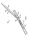
- FIGS 7 , 8 , 9 , and 10 are perspective views of an alternative embodiment of an adapter in accordance with the present invention as inserted into an opening formed in tissue.
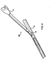
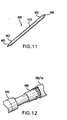
- Figure 11 is perspective view of an alternative embodiment of a connection element and distal sheath in accordance with the present invention.
- Figure 12 is a perspective view of the adapter, distal sheath and a medical instrument of Figure 11 .
- Figure 13 is a perspective view of the adapter of Figure 11 and a medical device in accordance with the present invention.
- Figure 14 is a perspective view of an exemplary embodiment of a connection element in accordance with the present invention.
- Figure 15 is a perspective view of the connection elements of Figure 14 and an exemplary embodiment of a clip according the present invention.
- Figure 16 is a perspective view of the connection element of the adapter and distal sheath wherein a clip is shown disposed thereabout to detachably attach the two connection elements.
- Figure 17 shows an exemplary embodiment of a clip tool according to the present invention.
- Figure 18 shows a left-side adapter and distal sheath mounted to a medical instrument, wherein the adapter, distal sheath and medical instrument are shown disposed in a tissue opening.
- Figure 19 shows a right side offset adapter mounted to a medical instrument as disposed through a tissue opening.
- Figure 20 is a partial view of a medical instrument which may be utilized with the present invention.
- Figure 21 is a top view of the tissue opening illustrating the multiple suture elements that may be placed to close the opening using the methods and devices of the present invention.
- Figure 22 is an isometric view of a kit in accordance with the present invention.
- an adapter described herein may be used with various medical instruments to change the effective circumference or size of a given medical instrument.
- Most suturing instruments that are used for closing vessel access punctures are available in limited ranges of sizes (such as 6 French to 10 French) that are applicable to most instances of percutaneous vessel access holes or punctures. In some instances, however, the vascular access puncture is much larger than the largest size instrument available.
- AAA access holes can be up to 25 French.
- the adapter described herein can be provided for use with a 6 Fr. instrument, for example, to provide an instrument that is effectively larger for use in the closure of larger vascular access punctures.
- One purpose of matching the instrument size to the hole size is to provide hemostasis, i.e., to block the outflow of blood through the puncture, during the suturing procedure.
- Another purpose may be to manipulate the periphery of the puncture into an elongated, elliptical or other non-circular shape so that maximum tissue capture is achieved.
- it is desirable for the needle punctures in the tissue through which the suture extends to be appropriately spaced from the periphery of the hole as possible to minimize the risk of suture tearing through tissue, while minimizing the overall diameter of the device.
- an adapter can be provided that hold the suturing instrument in a particular position with respect to the vessel puncture, so that multiple sutures can be placed at multiple locations across the puncture.
- suture loops can be placed to the right, near the center, and to the left across the puncture with respect to the longitudinal direction of the vessel, for example.
- the present invention is described and shown herein in used with a suture based medical instrument, it is contemplated that other medical instruments may be utilized with the adapter of the present invention.
- the adapter of the present invention may be utilized with other technologies such as clips, glues, staples and the like.
- an adapter or a plurality of adapters which can be combined to form a system for closing openings in tissue, wherein the adapters are configured to be detachably received on a medical instrument thereby altering the cross-sectional profile of a medical instrument utilized to close the opening.
- An exemplary embodiment of an adapter in accordance with the present invention includes a generally elongated member having a proximal and a distal end and a medical instrument holding portion, wherein the generally elongated member additionally includes at least one shim portion, the shim portion forming an enlarged cross-sectional area adjacent the medical instrument holding portion.
- the adapter may further include an aperture formed along the length of the elongated member, wherein the aperture is configured to receive a portion of the medical instrument therethrough.
- the present invention further includes a removable sheath which may be configured to be attached to a distal end or be received by the distal end of the medical instrument.
- medical instrument 10 is depicted herein as a suturing instrument for suturing or closing openings in tissue.
- a suitable suturing instrument can be seen in US Patent No. 6,136,010 , wherein the suturing instrument includes a handle portion, a distal shaft and an articulating foot member, wherein the foot includes suture elements which are configured to be received by needles which descend from the handle portion, thereby forming a loop of suture across an opening in which the medical instrument 10 has been disposed therethrough.
- the adapter 100 comprises an elongated body member 110 having a proximal end 102, central portion 103 and a distal end 104, wherein the adapter 100 further includes a groove or instrument receiving portion 140, wherein as shown in Figure 2 , the adapter is configured to be received on the "left side" of an instrument (not shown) from an operator's perspective relative to the medical instrument.
- the adapter 100 further includes at least one shim portion 120 wherein the shim portion may be disposed along a portion of the elongated body or as shown in the embodiment of Figure 5 , along the entire length of the elongated body. Additionally, the shim portion 120 is disposed adjacent the medical instrument receiving portion 140. The shim portion 120 provides an enlarged peripheral surface 122 adjacent the medical instrument (not shown) such that when the medical instrument is held in the instrument holding portion 140 and the medical instrument 10 and adapter 100 are inserted through an opening in a patient tissue at least a portion of the enlarged peripheral surface 122 may be in contact with at least a portion of the periphery of the opening in the patient tissue.
- a cutout, relieved portion, and/or aperture 124 may be provided at a location along the length of the elongated member 110, wherein the portion 124 may be configured to receive a guidewire or other instrument mechanism (not shown) to extend from the medical instrument as may be necessary.
- a bore 170 is optionally provided at the distal section 104 for accepting a distal sheath portion of a medical instrument upon mounting the adapter 100 on the medical instrument.
- the adapter 100 may further include a lumen 112 disposed within the shim portion 120 and extending at least partially therethrough and being configured to receive a guidewire or other medical device therein.
- the lumen 112 may also be configured to function as a blood marking lumen to allow a small amount of blood to flow through under pressure to an exit port disposed adjacent to the proximal end 102 (not shown), thereby providing visual feedback of placement of the adapter during use as will be described in greater detail below with regard to the methods of the present invention.
- the instrument holding portion 140 may additionally include an instrument engaging feature 150 or means for engaging the instrument (not shown) to hold the adapter 100 onto the medical instrument during use.
- An example of an instrument engaging feature is depicted in Figure 2 as a protrusion 152 that can be shaped to engage a corresponding detent in the body of the device, for example.
- Other embodiments of an instrument engaging feature may include a detent or indentation or a frictional surface, for example.
- the adapter 100 may be constructed wherein the medical instrument receiving portion 140 is resilient, therefore, the instrument receiving portion 140 is configured to "snap around" and receive the medical instrument 10.
- the medical instrument 10 may additionally include features formed thereon wherein the features formed onto the medical instrument and features formed on the adapter would be configured to received each other, thereby removably affixing the adapter to the medical instrument.
- Figure 3a shows an adapter 100 that is held or mounted on the "left side" of an instrument 10.
- Figure 3b shows an adapter 100 that is held or mounted on the "right side” of an instrument 10.
- Figure 3c shows an adapter 100 that is held or mounted on top of the instrument 10 such that the instrument is generally disposed over an upper surface, around the sides of, or surrounding a portion of the medical instrument when viewed from an operator's perspective.
- the retractable foot 12 of the medical instrument 10 is shown in a deployed position.
- a special introducer sheath having an appropriate cross-sectional profile and a hemostatic valve may be used together with the adapters shown in Figures 3a, 3b, and 3c such that two or more sutures can be placed to close an opening in tissue as will be described and shown below with regard to the method of use of the present invention.
- the use of a special introducer sheath would allow the exchange of multiple medical instruments during a surgical procedure while preventing excessive blood loss during the removal and placement of each medical instrument and corresponding adapter.
- the adapter 200 is configured to hold an instrument in a "centered" orientation relative to the opening formed in the tissue.
- Adapter 200 includes a body 210 having a first shim portion 220 and a second shim portion 230.
- the instrument holding portion 240 extends centrally between the first and second body portions.
- An aperture 280 is defined through the body 210 in the instrument holding portion 240. It should be noted that the instrument holding portion 240 can be offset from the center of the body 210 as well as centered in the body.
- Figure 5 illustrates the adapter 200 mounted or held on a medical instrument 10.
- the medical instrument 10 includes a distal section 16 extending through a bore 270 of the adapter 200.
- Figure 6 shows an underside view of the adapter 200 and instrument 10 of Figure 5 .
- Aperture 280 shown in Figure 6 , provides an aperture through which a medical instrument mechanism such as a foot 12 can be extended.
- the adapter 300 as shown in Figure 7 includes a body 310 having a shim portion 320 and an instrument holding portion 340.
- instrument holding portion 340 defines an enclosed instrument lumen 342, rather than an open groove such as in the embodiments previously describe.
- the enclosed instrument lumen 342 may include a hemostatic valve.
- the body 310 further includes a distal extension 360 extending longitudinally from the shim portion 320.
- a guidewire lumen 312 may be defined through the distal extension 360 and shim portion 320.
- a guidewire 302 is shown extending through the guidewire lumen 312.
- the adapter 300 is first advanced along the guidewire and into the opening 22 of the vessel 20.
- Figure 8 shows the adapter 300 in place.
- Figure 9 shows an instrument 10 inserted into the adapter 300 and further into the vessel 20. At this stage, the instrument 10 can be deployed to place a suture across the opening 22. The instrument is then removed from the adapter 300, leaving the adapter in place in the opening.
- Figure 10 shows the adapter 300 after it has been rotated 180 degrees to position the shim portion 320 and distal extension on the opposite side of the vessel.
- a second instrument (not shown) can be then advanced through the adapter to place a second stitch parallel to the first stitch.
- the removable sheath includes an elongated body having a proximal end, a distal end, and a tapered portion adjacent the distal end, wherein a bore extends from the proximal end to the distal end, a guidewire lumen may extend through the tapered distal tip, wherein a hemostasis valve may be disposed in the tapered distal tip or anywhere along the bore of the removable sheath. It is further contemplated that an additional guidewire/marker lumen may extend between the distal tip/end and the proximal end.
- the removable sheath further includes a connection element disposed adjacent to the proximal end thereof, the connection element configured to detachably attach the proximal end of the removable sheath to a medical instrument, wherein the medical instrument includes a similar connection element.
- the distal sheath 400 comprises and elongated member 410 having a proximal end 402, a distal end 403 and a tapered distal tip 405, a bore 406 (not shown) extends from the proximal end to the distal end, wherein the bore is configured to receive a distal end of a medical instrument as will be shown and described in greater detail with regard to the methods of the present invention.
- the tapered distal tip may further include a lumen therethrough (not shown) wherein the lumen may be configured to receive a guidewire or function as a marker lumen.
- the distal sheath 400 may further include a hemostasis valve, wherein the hemostasis valve may be disposed at any location along the length of the elongated member and including the tapered distal tip.
- a second lumen may be disposed along the length of the elongated member 410, wherein the second lumen would be generally parallel to the bore and may be utilized as a marker lumen or a guidewire lumen.
- the distal sheath 400 further includes a connection element 450, wherein the connection element 450 is disposed adjacent the proximal end 402 of the distal sheath.
- the connection element is configured to engage a similar connection element disposed on the medical instrument 10 or adapter 100, thereby detachably attaching the distal sheath 400 to the medical instrument 10 or adapter 100.
- connection element 450 disposed on the distal sheath 400 comprises a female threaded member, wherein the connection element 460 disposed on the adapter 100 and/or medical instrument 10 comprises male threads, wherein the female threaded portion of the connection element 450 is configured to engage the male threaded portion 460 of the adapter/medical instrument thereby allowing the two pieces to be detachably attached, thereby forming a medical instrument 15 as shown in Figure 13 , wherein the medical instrument 15, comprises distal sheath 400, adapter 100 and a medical instrument 10, wherein the adapter 100 may comprise a "left, center, or right" adapter as described in detail above.
- the second connection element 460 may be disposed on the medical device 10 or alternatively upon the adapter 100.
- the adapter and distal sheath may be utilized with any medical instrument which is compatible with the present invention. Additionally, this may lead to reduced costs as well being that a currently existing medical instrument may be utilized with the adapter and distal sheath rather than having to custom manufacture a different medical instrument.
- connection element 450 is shown disposed on the proximal end 402 of the distal sheath 400 and a second connection element 460 is shown disposed on the distal end of an adapter in accordance with the present invention, additionally a clip 470 is shown disposed on the connection element 460 associated with the adapter.
- the adapter 100 has been detachably attached to a medical instrument 10, wherein the distal end of the medical instrument 10 extends through the connection element 460 and the clip 470, wherein the distal end of the medical instrument is configured to be received within the bore 450 of the distal sheath 400 as shown in Figure 15 (clip 470 omitted for clarity).
- the first connection element 450 and the second connection element 460 are configured such alignment elements disposed on the connection elements align the distal sheath and the adapter in proper alignment and provide means to transmit torque along the assembly.
- the clip 470 is configured to received the first connector element 450 and the second connector element 460, wherein the clip detachably retains the two connector elements in an aligned position.
- the clip 470 is configured to retain the two connector elements with sufficient force such that the two connector elements cannot be easily separated during use.
- One of the two connector elements or both connector elements may be separated by applying a force to either the adapter or the distal sheath.
- the clip 470 is configured to have a low profile, equal to or substantially equal to that of the connector elements, adapter and/or distal sheath, such that in use the clip 470 does not present any sharp surfaces or enlarged surfaces which may cause procedural complications.
- a clip tool 500 is utilized to detach the first and second connector elements, wherein the clip tool 500 may also be utilized to remove a clip which retains the first and second connector elements.
- An exemplary embodiment of a clip tool is shown in Figure 17 , wherein the clip tool includes a first member including a first clip engaging portion and a second member including a clip engaging portion, wherein the first and second members oppose one another and may include a biasing member to retain the first and second members in a biased position.
- the clip is placed in the first clip engaging portion and the second clip engaging portion is advanced, wherein the second clip engaging portion engages the clip, thereby opening the clip such that the first and second connection elements may be disengaged from each other.
- connection elements may be utilized to perform the same or similar function of the clip and connection elements described above.
- a connector element may be configured wherein the connection element comprises a male and female element wherein one of the elements can be detached from the other through the use of an applied force.
- the applied force may be applied longitudinally, axially, or along any axis of the adapter, distal sheath, medical instrument, and the like.
- FIG. 18-21 there is shown the apparatuses of the present invention in use, wherein exemplary embodiments of each of the elements of the present invention are shown in use to close an opening formed in tissue.
- a "left" adapter 100 is shown to be mounted to a medical instrument 10, and distal sheath 400 is shown attached to the distal end of the adapter 100.
- the medical instrument 10 together with the adapter 100 have been positioned through an opening 22 in a vessel wall 20.
- FIG 19 there is shown an enlarged view of the portion of the medical instrument and adapter according to the present invention as indicated by line 2-2 of Figure 18 .
- the adapter 100 is shown mounted to the left side of the instrument 10, in this exemplary embodiment.
- the instrument mechanism 12 can be an articulating "foot,” or needle ports as described in detail above with reference to the medical instrument 10.
- Figure 20 shows the instrument 10 positioned through subcutaneous tissue 30 of a patient.
- the subcutaneous tissue 30 has a tissue tract 32 formed therein, which is a hole at the bottom of which is the opening 22 of the vessel wall 20.
- Instrument 10 is shown with its foot or instrument mechanism 12 deployed and needles 18 extending from the proximal shaft 14 of the instrument 10 to the mechanism 12.
- the structure and operation of the instrument 10 is described more fully in U.S. Patent No. 6, 136,010 .
- Figure 21 shows examples of suture patterns across an opening 22 in a vessel wall 20. Pairs of needle punctures 26, 26', and 26" are shown in the vessel wall 20. Suture loops 40, 40', and 40" are shown extending through respective pairs of needle punctures. Each suture loop can be tied individually to provide a plurality of stitches across opening 22 to close the opening. The ends of the suture loops can be tied to non-corresponding ends to result in crossed stitch patterns or a pattern similar to a mattress stitch, as desired.
- the device in accordance with the present invention may be utilized to partially close a large opening by placing at least one suture, after partially closing the opening, an additional medical procedure could be performed through the smaller opening, then the smaller opening can be closed using the methods and devices disclosed herein after completion of the procedure.
- the detachable distal sheath is inserted into the femoral artery over a guidewire in a manner similar to that of a common introducer sheath.
- the instruments are provided with adapters one at a time.
- the first instrument is deployed, its adapter is detached from the distal sheath and the first instrument with attached adapter is removed from the distal sheath.
- the sheath remains in place to maintain hemostasis while an instrument exchange occurs. The above described method continues to occur until a sufficient number of sutures have been placed to close the opening in the tissue.
- a medical instrument having a first adapter would be inserted into the opening using a known technique, wherein a first suture would be deployed, the medical instrument would be withdrawn a sufficient amount from the opening to expose the clip.
- the clip would be removed from the device as described above, a second medical instrument may then be attached to the distal sheath using the clip, wherein the medical instrument would include an adapter having a profile differing from that of the previous adapter.
- the above process continues until a sufficient number of sutures have been placed to close the opening.
- the medical instrument including the adapter and distal sheath may be removed from the opening while a tension force is applied to the sutures to control bleeding if required. If not, the medical instrument and adapter may be removed from the distal sheath, wherein the distal sheath may be utilized to maintain hemostasis.
- adapter can be used with other types of medical instruments, for example, stapling or other non-suture based vessel closure devices are contemplated for use with the adapter embodiments of the present invention. It is contemplated that the adapter(s), connector elements, clip, and distal sheath may be constructed of any material, in a preferred embodiment a biocompatible material is utilized. Additionally, any or all of the components of the present invention may include a coating, the coating may be embodied as a hydrophilic coating, a beneficial agent or any other biocompatible coating.
- the kit includes at least one medical instrument, and a distal sheath, wherein the medical instrument includes an integrated adapter in accordance with the present invention.
- the kit preferably includes at least two medical instruments and a distal sheath.
- the medical instrument of the kit illustrated in Figure 22 is similar to the medical instrument described above and in US Patent No. 6,136,010 the entirety of which is herein incorportated by reference, and US Patent Application NO. 2003/00093093 and Attorney Docket No. 6771USP3 filed August 29, 2003 and 6771USP4 filed September 11, 2003 respectively.
- the suturing instrument includes a handle portion, a distal shaft and an articulating foot member, wherein the foot includes suture elements which are configured to be received by needles which descend from the handle portion, thereby forming a loop of suture across an opening in which the medical instrument 10 has been disposed therethrough.
- each medical instrument of the kit includes an adapter integrally formed onto a distal section of the medical instrument, wherein each medical instrument includes an adapter having different geometry.
- each medical device would have an adapter having different geometry, for example, the medical instruments would have a left, right and center geometry as described in detail above.
- the medical instruments would include a connector element 460 similar to that described above, wherein the sheath 400 would also include a connector element 450, the two connector elements configured to engage each other, wherein a separate clip may be utilized to retain the two connector elements, or alternatively, the connector elements may have geometry which is configured to retain the two connectors independent of a separate element.
- the distal sheath is attached to the distal end of the medical instrument, wherein the assembly would then be inserted into an opening formed in a patients tissue, this may be accomplished by passing the assembly over a guidewire or through a sheath.
- the assembly is partially retracted from the opening until the connector elements are accessible.
- a tool such as that shown in Figure 17 may be used to separate the distal sheath from the medical instrument.
- the medical instrument may then be retracted from the distal sheath, wherein the distal sheath remains within the opening to provide hemostasis.
- a second medical instrument having a different adapter profile may then be attached to the distal sheath and the assembly advanced into the opening, wherein a second suture is deployed adjacent to the opening. This process may be repeated a number of times until a sufficient number of sutures have been placed adjacent the opening to provide sufficient closure of the opening. Once a sufficient number of sutures have been placed, the final assembly (medical instrument and distal sheath) is then removed from the opening, knots may be formed and the opening may be closed.
Claims (7)
- Ein Adapter (100) für ein medizinisches Instrument (10), wobei der Adapter Folgendes umfasst:einen Körper mit einem Abstandscheiben-Abschnitt (120) und einem Instrumenten-Halteabschnitt (140) neben dem Abstandscheiben-Abschnitt (120), wobei der Abstandscheiben-Abschnitt (120) eine vergrößerte periphere Oberfläche angrenzend an das medizinische Instrument (10) bereitstellt, so dass, wenn das medizinische Instrument (10) in dem Instrumenten-Halteabschnitt (140) gehalten wird und das medizinische Instrument (10) und der Körper durch eine Öffnung in einem Patientengewebe eingeführt werden, mindestens ein Abschnitt der vergrößerten peripheren Oberfläche im Kontakt mit mindestens einem Abschnitt der Peripherie der Öffnung im Patientengewebe steht,dadurch gekennzeichnet, dass der Adapter (100) weiter eine lösbare distale Hülse (400) umfasst, wobei die lösbare distale Hülse (400) ein Hämostase-Ventil einschließt und ausgebildet ist, um am distalen Ende des Adapters (100) oder am distalen Ende des medizinischen Instruments (10) angebracht zu werden.
- Der Adapter gemäß Anspruch 1, wobei der Adapter (100) aus einem biegsamen Material hergestellt ist, wobei der Adapter ausgebildet ist, um sich einem Profil des medizinischen Instruments (10) anzugleichen.
- Der Adapter gemäß Anspruch 1, wobei der Adapter weiter einen zweiten Adapter (200) einschließt, wobei der zweite Adapter einen Körper mit einem Abstandscheiben-Abschnitt (220) und einem Instrumenten-Halteabschnitt (240) neben dem Abstandscheiben-Abschnitt (220) hat, wobei der Abstandscheiben-Abschnitt (220) eine vergrößerte periphere Oberfläche angrenzend an das medizinische Instrument (10) bereitstellt, so dass, wenn das medizinische Instrument (10) in dem Instrumenten-Halteabschnitt (240) gehalten wird und das medizinische Instrument (10) und der Körper durch eine Öffnung in einem Patientengewebe eingeführt werden, mindestens ein Abschnitt der vergrößerten peripheren Oberfläche im Kontakt mit mindestens einem Abschnitt der Peripherie der Öffnung im Patientengewebe steht, wobei die Instrumenten-Halteposition des zweiten Adapters sich von derjenigen des ersten Adapters unterscheidet.
- Der Adapter gemäß Anspruch 3, wobei der Adapter (200) weiter einen dritten Adapter (300) einschließt, wobei der dritte Adapter (300) einen Körper mit einem Abstandscheiben-Abschnitt (320) und einem Instrumenten-Halteabschnitt (340) neben dem Abstandscheiben-Abschnitt (320) hat, wobei der Abstandscheiben-Abschnitt (320) eine vergrößerte periphere Oberfläche angrenzend an das medizinische Instrument (10) bereitstellt, so dass, wenn das medizinische Instrument (10) in dem Instrumenten-Halteabschnitt (340) gehalten wird und das medizinische Instrument (10) und der Körper durch eine Öffnung in einem Patientengewebe eingeführt werden, mindestens ein Abschnitt der vergrößerten peripheren Oberfläche im Kontakt mit mindestens einem Abschnitt der Peripherie der Öffnung im Patientengewebe steht, wobei die Instrumenten-Halteposition des dritten Adapters sich von derjenigen des ersten und des zweiten Adapters unterscheidet.
- Der Adapter gemäß Anspruch 1, wobei der Instrumenten-Halteabschnitt (140) eine Rille mindestens teilweise entlang der Länge des Körpers bestimmt, so dass das medizinische Instrument (10) seitlich durch die Rille in den Instrumenten-Halteabschnitt eingeführt werden kann.
- Der Adapter gemäß Anspruch 5, wobei der Abstandscheiben-Abschnitt zwei Abstandscheiben-Abschnitte umfasst, wobei einer neben einem proximalen Ende angeordnet ist und einer neben einem distalen Ende angeordnet ist, und weiter eine reduzierte Querschnittsfläche, die dazwischen angeordnet ist, einschließend.
- Der Adapter gemäß Anspruch 1, wobei der Adapter eine Verbindungsvorrichtung (450) einschließt, die geeignet ist, die distale Hülse lösbar zu verbinden.
Applications Claiming Priority (3)
| Application Number | Priority Date | Filing Date | Title |
|---|---|---|---|
| US47657303P | 2003-06-06 | 2003-06-06 | |
| US50231603P | 2003-09-12 | 2003-09-12 | |
| PCT/US2004/018028 WO2004107990A1 (en) | 2003-06-06 | 2004-06-04 | Sizing and positioning adapter for medical instruments |
Publications (2)
| Publication Number | Publication Date |
|---|---|
| EP1631199A1 EP1631199A1 (de) | 2006-03-08 |
| EP1631199B1 true EP1631199B1 (de) | 2008-09-10 |
Family
ID=33514086
Family Applications (1)
| Application Number | Title | Priority Date | Filing Date |
|---|---|---|---|
| EP04754595A Not-in-force EP1631199B1 (de) | 2003-06-06 | 2004-06-04 | Anpassungs- und positionierungsadapter für medizinische instrumente |
Country Status (7)
| Country | Link |
|---|---|
| US (4) | US8715303B2 (de) |
| EP (1) | EP1631199B1 (de) |
| JP (1) | JP2006527029A (de) |
| AT (1) | ATE407628T1 (de) |
| AU (1) | AU2004245108B2 (de) |
| DE (1) | DE602004016498D1 (de) |
| WO (1) | WO2004107990A1 (de) |
Families Citing this family (10)
| Publication number | Priority date | Publication date | Assignee | Title |
|---|---|---|---|---|
| US8715303B2 (en) | 2003-06-06 | 2014-05-06 | Abbott Laboratories | Sizing and positioning adapter for medical instruments |
| US8292150B2 (en) | 2010-11-02 | 2012-10-23 | Tyco Healthcare Group Lp | Adapter for powered surgical devices |
| US10085744B2 (en) | 2014-12-08 | 2018-10-02 | Covidien Lp | Loading unit attachment band for surgical stapling instrument |
| US10117656B2 (en) | 2015-01-07 | 2018-11-06 | Covidien Lp | Loading unit locking collar |
| US10022126B2 (en) | 2015-01-07 | 2018-07-17 | Covidien Lp | Loading unit locking collar |
| US10039549B2 (en) | 2015-01-07 | 2018-08-07 | Covidien Lp | Loading unit retention clip for surgical stapling instrument |
| US10881408B2 (en) | 2015-04-22 | 2021-01-05 | Covidien Lp | Interlock assembly for replaceable loading units |
| US10117655B2 (en) * | 2015-07-22 | 2018-11-06 | Covidien Lp | Loading unit locking band for surgical stapling instrument |
| US9980730B2 (en) | 2015-09-21 | 2018-05-29 | Covidien Lp | Loading unit locking collar with rotational actuated release |
| US11141162B2 (en) | 2016-07-08 | 2021-10-12 | Covidien Lp | Loading unit locking collar with linearly actuated release |
Family Cites Families (52)
| Publication number | Priority date | Publication date | Assignee | Title |
|---|---|---|---|---|
| DE3025785C2 (de) * | 1980-07-08 | 1984-08-16 | Storz, Karl, 7200 Tuttlingen | Dilatator, Verfahren zu seiner Verwendung und Vorrichtung zur Durchführung des Verfahrens |
| US4435174A (en) * | 1982-04-12 | 1984-03-06 | American Hospital Supply Corporation | Catheter guide |
| JPS59103644A (ja) * | 1982-12-07 | 1984-06-15 | オリンパス光学工業株式会社 | 内視鏡撮像装置 |
| DE8407894U1 (de) * | 1984-03-15 | 1984-09-06 | Richard Wolf Gmbh, 7134 Knittlingen | Dilatator zum aufweiten von einstichkanaelen der niere |
| US4862891A (en) * | 1988-03-14 | 1989-09-05 | Canyon Medical Products | Device for sequential percutaneous dilation |
| US4944287A (en) * | 1988-03-29 | 1990-07-31 | Asahi Kogaku Kogyo K.K. | Flexible tube of endoscope |
| US4994027A (en) * | 1988-06-08 | 1991-02-19 | Farrell Edward M | Percutaneous femoral bypass system |
| US5193263A (en) * | 1989-07-19 | 1993-03-16 | Asahi Kogaku Kogyo Kabushiki Kaisha | Method of securing skin tube to bendable tube portion of endoscope |
| US5257617A (en) * | 1989-12-25 | 1993-11-02 | Asahi Kogaku Kogyo Kabushiki Kaisha | Sheathed endoscope and sheath therefor |
| US5071410A (en) * | 1991-03-14 | 1991-12-10 | Pazell John A | Arthroscopic surgery system |
| US5676689A (en) | 1991-11-08 | 1997-10-14 | Kensey Nash Corporation | Hemostatic puncture closure system including vessel location device and method of use |
| US5304184A (en) | 1992-10-19 | 1994-04-19 | Indiana University Foundation | Apparatus and method for positive closure of an internal tissue membrane opening |
| US5417699A (en) | 1992-12-10 | 1995-05-23 | Perclose Incorporated | Device and method for the percutaneous suturing of a vascular puncture site |
| US6036699A (en) * | 1992-12-10 | 2000-03-14 | Perclose, Inc. | Device and method for suturing tissue |
| GB2275420B (en) * | 1993-02-22 | 1996-10-09 | David Ramon Gaunt | Organ access systems and trocar assemblies |
| US5827299A (en) * | 1993-08-25 | 1998-10-27 | Inlet Medical, Inc | Insertable suture passing grasping probe and methodology for using same |
| US5527322A (en) | 1993-11-08 | 1996-06-18 | Perclose, Inc. | Device and method for suturing of internal puncture sites |
| US5431666A (en) | 1994-02-24 | 1995-07-11 | Lasersurge, Inc. | Surgical suture instrument |
| US5496332A (en) * | 1994-10-20 | 1996-03-05 | Cordis Corporation | Wound closure apparatus and method for its use |
| US5562686A (en) | 1995-04-19 | 1996-10-08 | United States Surgical Corporation | Apparaus and method for suturing body tissue |
| US5902311A (en) | 1995-06-15 | 1999-05-11 | Perclose, Inc. | Low profile intraluminal suturing device and method |
| US5759150A (en) * | 1995-07-07 | 1998-06-02 | Olympus Optical Co., Ltd. | System for evulsing subcutaneous tissue |
| US5846253A (en) * | 1995-07-14 | 1998-12-08 | C. R. Bard, Inc. | Wound closure apparatus and method |
| US5700273A (en) * | 1995-07-14 | 1997-12-23 | C.R. Bard, Inc. | Wound closure apparatus and method |
| AU6858896A (en) * | 1995-08-24 | 1997-03-19 | Nobles-Lai Engineering, Inc. | Method and apparatus for suturing |
| US6117144A (en) * | 1995-08-24 | 2000-09-12 | Sutura, Inc. | Suturing device and method for sealing an opening in a blood vessel or other biological structure |
| US6562052B2 (en) * | 1995-08-24 | 2003-05-13 | Sutura, Inc. | Suturing device and method |
| US5792044A (en) * | 1996-03-22 | 1998-08-11 | Danek Medical, Inc. | Devices and methods for percutaneous surgery |
| US6436109B1 (en) | 1996-06-11 | 2002-08-20 | X-Site, L.L.C. | Device and method for suturing blood vessels and the like |
| US6346093B1 (en) * | 1996-09-13 | 2002-02-12 | Scimed Life Systems, Inc. | Single operator exchange biliary catheter with common distal lumen |
| US6190357B1 (en) * | 1998-04-21 | 2001-02-20 | Cardiothoracic Systems, Inc. | Expandable cannula for performing cardiopulmonary bypass and method for using same |
| US6126058A (en) * | 1998-06-19 | 2000-10-03 | Scimed Life Systems, Inc. | Method and device for full thickness resectioning of an organ |
| US6334865B1 (en) * | 1998-08-04 | 2002-01-01 | Fusion Medical Technologies, Inc. | Percutaneous tissue track closure assembly and method |
| US20040092964A1 (en) * | 1999-03-04 | 2004-05-13 | Modesitt D. Bruce | Articulating suturing device and method |
| US6964668B2 (en) * | 1999-03-04 | 2005-11-15 | Abbott Laboratories | Articulating suturing device and method |
| US7001400B1 (en) * | 1999-03-04 | 2006-02-21 | Abbott Laboratories | Articulating suturing device and method |
| US7235087B2 (en) * | 1999-03-04 | 2007-06-26 | Abbott Park | Articulating suturing device and method |
| US6136010A (en) | 1999-03-04 | 2000-10-24 | Perclose, Inc. | Articulating suturing device and method |
| AUPQ362199A0 (en) * | 1999-10-22 | 1999-11-18 | Kaladelfos, George | Intra-vaginal sling placement device |
| US6641592B1 (en) * | 1999-11-19 | 2003-11-04 | Lsi Solutions, Inc. | System for wound closure |
| US6391048B1 (en) | 2000-01-05 | 2002-05-21 | Integrated Vascular Systems, Inc. | Integrated vascular device with puncture site closure component and sealant and methods of use |
| US6517518B2 (en) * | 2000-03-10 | 2003-02-11 | Kensey Nash Corporation | Tool for facilitating the connecting of a catheter or other tubular member onto a guide-wire without access to the ends of the guide-wire |
| US6997931B2 (en) * | 2001-02-02 | 2006-02-14 | Lsi Solutions, Inc. | System for endoscopic suturing |
| US20030073934A1 (en) * | 2001-10-17 | 2003-04-17 | David A. Putz | Double slotted-cannula device and method of use |
| US8088143B2 (en) | 2002-06-12 | 2012-01-03 | Radi Medical Systems Ab | Closure device |
| DE60200515T2 (de) | 2002-06-12 | 2004-09-30 | Radi Medical Systems Ab | Verschlussvorrichtung |
| US7160309B2 (en) * | 2002-12-31 | 2007-01-09 | Laveille Kao Voss | Systems for anchoring a medical device in a body lumen |
| US20040225301A1 (en) * | 2003-05-05 | 2004-11-11 | St. Jude Medical, Daig Division, Inc. | Loop closure apparatus and method |
| US8715303B2 (en) | 2003-06-06 | 2014-05-06 | Abbott Laboratories | Sizing and positioning adapter for medical instruments |
| US7449024B2 (en) * | 2003-12-23 | 2008-11-11 | Abbott Laboratories | Suturing device with split arm and method of suturing tissue |
| KR101773205B1 (ko) | 2009-04-09 | 2017-09-12 | 카디오배스큘러 테크놀러지스 인코포레이티드 | 조직 봉합 장치, 이송 장치 및 시스템, 키트 및 이를 위한 방법 |
| US10085735B2 (en) * | 2014-10-29 | 2018-10-02 | Smith & Nephew, Inc. | Modular tissue repair kit and devices and method related thereto |
-
2004
- 2004-06-04 US US10/861,171 patent/US8715303B2/en not_active Expired - Fee Related
- 2004-06-04 DE DE602004016498T patent/DE602004016498D1/de active Active
- 2004-06-04 EP EP04754595A patent/EP1631199B1/de not_active Not-in-force
- 2004-06-04 AU AU2004245108A patent/AU2004245108B2/en not_active Ceased
- 2004-06-04 JP JP2006515260A patent/JP2006527029A/ja not_active Withdrawn
- 2004-06-04 WO PCT/US2004/018028 patent/WO2004107990A1/en active Application Filing
- 2004-06-04 AT AT04754595T patent/ATE407628T1/de not_active IP Right Cessation
-
2014
- 2014-05-05 US US14/269,792 patent/US9592045B2/en not_active Expired - Fee Related
-
2017
- 2017-03-07 US US15/452,099 patent/US10327760B2/en not_active Expired - Fee Related
-
2019
- 2019-04-24 US US16/393,315 patent/US20190247040A1/en not_active Abandoned
Also Published As
| Publication number | Publication date |
|---|---|
| US10327760B2 (en) | 2019-06-25 |
| AU2004245108A1 (en) | 2004-12-16 |
| WO2004107990A1 (en) | 2004-12-16 |
| US8715303B2 (en) | 2014-05-06 |
| US20140243854A1 (en) | 2014-08-28 |
| EP1631199A1 (de) | 2006-03-08 |
| US20050021047A1 (en) | 2005-01-27 |
| AU2004245108B2 (en) | 2010-03-11 |
| JP2006527029A (ja) | 2006-11-30 |
| US20190247040A1 (en) | 2019-08-15 |
| US9592045B2 (en) | 2017-03-14 |
| WO2004107990A9 (en) | 2005-07-21 |
| ATE407628T1 (de) | 2008-09-15 |
| DE602004016498D1 (de) | 2008-10-23 |
| US20170172566A1 (en) | 2017-06-22 |
Similar Documents
| Publication | Publication Date | Title |
|---|---|---|
| US10327760B2 (en) | Sizing and positioning adapter for medical instruments | |
| US7951167B2 (en) | Fluidtight puncturing and occlusion device for anatomical structure | |
| US10980531B2 (en) | Systems, methods, and devices for closing holes in body lumens | |
| US6010514A (en) | Suturing assembly and method of use | |
| US9592038B2 (en) | Vascular suturing device | |
| US7144411B2 (en) | Apparatus and methods for positioning a vascular sheath | |
| US6024747A (en) | Device and method for suturing blood vessels and the like | |
| US6949107B2 (en) | Injection method for locating vessel lumen | |
| US8956388B2 (en) | Integrated vascular device with puncture site closure component and sealant | |
| US5531763A (en) | Suture cinching apparatus | |
| US20070032801A1 (en) | Vascular suturing device | |
| US20120004671A1 (en) | Suture loop closure device | |
| US20120179174A1 (en) | Surgical device | |
| EP2298180A1 (de) | Nahtvorrichtung mit Gelenken | |
| JP2008500125A (ja) | 縫合デバイス | |
| US7637925B2 (en) | Surgical staple | |
| US10426449B2 (en) | Articulating suturing device with improved actuation and alignment mechanisms | |
| JPH07136177A (ja) | 生物学的適合性縫い糸クリップ | |
| KR100396479B1 (ko) | 의료용실부착바늘의유도기구 |
Legal Events
| Date | Code | Title | Description |
|---|---|---|---|
| PUAI | Public reference made under article 153(3) epc to a published international application that has entered the european phase |
Free format text: ORIGINAL CODE: 0009012 |
|
| 17P | Request for examination filed |
Effective date: 20051205 |
|
| AK | Designated contracting states |
Kind code of ref document: A1 Designated state(s): AT BE BG CH CY CZ DE DK EE ES FI FR GB GR HU IE IT LI LU MC NL PL PT RO SE SI SK TR |
|
| DAX | Request for extension of the european patent (deleted) | ||
| REG | Reference to a national code |
Ref country code: HK Ref legal event code: DE Ref document number: 1088807 Country of ref document: HK |
|
| 17Q | First examination report despatched |
Effective date: 20070417 |
|
| GRAP | Despatch of communication of intention to grant a patent |
Free format text: ORIGINAL CODE: EPIDOSNIGR1 |
|
| GRAS | Grant fee paid |
Free format text: ORIGINAL CODE: EPIDOSNIGR3 |
|
| GRAA | (expected) grant |
Free format text: ORIGINAL CODE: 0009210 |
|
| AK | Designated contracting states |
Kind code of ref document: B1 Designated state(s): AT BE BG CH CY CZ DE DK EE ES FI FR GB GR HU IE IT LI LU MC NL PL PT RO SE SI SK TR |
|
| REG | Reference to a national code |
Ref country code: GB Ref legal event code: FG4D |
|
| REG | Reference to a national code |
Ref country code: CH Ref legal event code: EP |
|
| REG | Reference to a national code |
Ref country code: IE Ref legal event code: FG4D |
|
| REF | Corresponds to: |
Ref document number: 602004016498 Country of ref document: DE Date of ref document: 20081023 Kind code of ref document: P |
|
| PG25 | Lapsed in a contracting state [announced via postgrant information from national office to epo] |
Ref country code: SI Free format text: LAPSE BECAUSE OF FAILURE TO SUBMIT A TRANSLATION OF THE DESCRIPTION OR TO PAY THE FEE WITHIN THE PRESCRIBED TIME-LIMIT Effective date: 20080910 Ref country code: AT Free format text: LAPSE BECAUSE OF FAILURE TO SUBMIT A TRANSLATION OF THE DESCRIPTION OR TO PAY THE FEE WITHIN THE PRESCRIBED TIME-LIMIT Effective date: 20080910 Ref country code: FI Free format text: LAPSE BECAUSE OF FAILURE TO SUBMIT A TRANSLATION OF THE DESCRIPTION OR TO PAY THE FEE WITHIN THE PRESCRIBED TIME-LIMIT Effective date: 20080910 |
|
| PG25 | Lapsed in a contracting state [announced via postgrant information from national office to epo] |
Ref country code: BE Free format text: LAPSE BECAUSE OF FAILURE TO SUBMIT A TRANSLATION OF THE DESCRIPTION OR TO PAY THE FEE WITHIN THE PRESCRIBED TIME-LIMIT Effective date: 20080910 |
|
| PG25 | Lapsed in a contracting state [announced via postgrant information from national office to epo] |
Ref country code: BG Free format text: LAPSE BECAUSE OF FAILURE TO SUBMIT A TRANSLATION OF THE DESCRIPTION OR TO PAY THE FEE WITHIN THE PRESCRIBED TIME-LIMIT Effective date: 20081210 Ref country code: ES Free format text: LAPSE BECAUSE OF FAILURE TO SUBMIT A TRANSLATION OF THE DESCRIPTION OR TO PAY THE FEE WITHIN THE PRESCRIBED TIME-LIMIT Effective date: 20081221 |
|
| PG25 | Lapsed in a contracting state [announced via postgrant information from national office to epo] |
Ref country code: PT Free format text: LAPSE BECAUSE OF FAILURE TO SUBMIT A TRANSLATION OF THE DESCRIPTION OR TO PAY THE FEE WITHIN THE PRESCRIBED TIME-LIMIT Effective date: 20090210 Ref country code: SK Free format text: LAPSE BECAUSE OF FAILURE TO SUBMIT A TRANSLATION OF THE DESCRIPTION OR TO PAY THE FEE WITHIN THE PRESCRIBED TIME-LIMIT Effective date: 20080910 Ref country code: RO Free format text: LAPSE BECAUSE OF FAILURE TO SUBMIT A TRANSLATION OF THE DESCRIPTION OR TO PAY THE FEE WITHIN THE PRESCRIBED TIME-LIMIT Effective date: 20080910 Ref country code: CZ Free format text: LAPSE BECAUSE OF FAILURE TO SUBMIT A TRANSLATION OF THE DESCRIPTION OR TO PAY THE FEE WITHIN THE PRESCRIBED TIME-LIMIT Effective date: 20080910 |
|
| PLBE | No opposition filed within time limit |
Free format text: ORIGINAL CODE: 0009261 |
|
| STAA | Information on the status of an ep patent application or granted ep patent |
Free format text: STATUS: NO OPPOSITION FILED WITHIN TIME LIMIT |
|
| PG25 | Lapsed in a contracting state [announced via postgrant information from national office to epo] |
Ref country code: DK Free format text: LAPSE BECAUSE OF FAILURE TO SUBMIT A TRANSLATION OF THE DESCRIPTION OR TO PAY THE FEE WITHIN THE PRESCRIBED TIME-LIMIT Effective date: 20080910 Ref country code: EE Free format text: LAPSE BECAUSE OF FAILURE TO SUBMIT A TRANSLATION OF THE DESCRIPTION OR TO PAY THE FEE WITHIN THE PRESCRIBED TIME-LIMIT Effective date: 20080910 |
|
| 26N | No opposition filed |
Effective date: 20090611 |
|
| PG25 | Lapsed in a contracting state [announced via postgrant information from national office to epo] |
Ref country code: SE Free format text: LAPSE BECAUSE OF FAILURE TO SUBMIT A TRANSLATION OF THE DESCRIPTION OR TO PAY THE FEE WITHIN THE PRESCRIBED TIME-LIMIT Effective date: 20081210 Ref country code: MC Free format text: LAPSE BECAUSE OF NON-PAYMENT OF DUE FEES Effective date: 20090630 |
|
| REG | Reference to a national code |
Ref country code: CH Ref legal event code: PL |
|
| PG25 | Lapsed in a contracting state [announced via postgrant information from national office to epo] |
Ref country code: CH Free format text: LAPSE BECAUSE OF NON-PAYMENT OF DUE FEES Effective date: 20090630 Ref country code: LI Free format text: LAPSE BECAUSE OF NON-PAYMENT OF DUE FEES Effective date: 20090630 Ref country code: IE Free format text: LAPSE BECAUSE OF NON-PAYMENT OF DUE FEES Effective date: 20090604 |
|
| PG25 | Lapsed in a contracting state [announced via postgrant information from national office to epo] |
Ref country code: PL Free format text: LAPSE BECAUSE OF FAILURE TO SUBMIT A TRANSLATION OF THE DESCRIPTION OR TO PAY THE FEE WITHIN THE PRESCRIBED TIME-LIMIT Effective date: 20080910 |
|
| PG25 | Lapsed in a contracting state [announced via postgrant information from national office to epo] |
Ref country code: GR Free format text: LAPSE BECAUSE OF FAILURE TO SUBMIT A TRANSLATION OF THE DESCRIPTION OR TO PAY THE FEE WITHIN THE PRESCRIBED TIME-LIMIT Effective date: 20081211 |
|
| PG25 | Lapsed in a contracting state [announced via postgrant information from national office to epo] |
Ref country code: LU Free format text: LAPSE BECAUSE OF NON-PAYMENT OF DUE FEES Effective date: 20090604 |
|
| PG25 | Lapsed in a contracting state [announced via postgrant information from national office to epo] |
Ref country code: HU Free format text: LAPSE BECAUSE OF FAILURE TO SUBMIT A TRANSLATION OF THE DESCRIPTION OR TO PAY THE FEE WITHIN THE PRESCRIBED TIME-LIMIT Effective date: 20090311 |
|
| PG25 | Lapsed in a contracting state [announced via postgrant information from national office to epo] |
Ref country code: TR Free format text: LAPSE BECAUSE OF FAILURE TO SUBMIT A TRANSLATION OF THE DESCRIPTION OR TO PAY THE FEE WITHIN THE PRESCRIBED TIME-LIMIT Effective date: 20080910 |
|
| PG25 | Lapsed in a contracting state [announced via postgrant information from national office to epo] |
Ref country code: CY Free format text: LAPSE BECAUSE OF FAILURE TO SUBMIT A TRANSLATION OF THE DESCRIPTION OR TO PAY THE FEE WITHIN THE PRESCRIBED TIME-LIMIT Effective date: 20080910 |
|
| REG | Reference to a national code |
Ref country code: HK Ref legal event code: WD Ref document number: 1088807 Country of ref document: HK |
|
| PGFP | Annual fee paid to national office [announced via postgrant information from national office to epo] |
Ref country code: FR Payment date: 20140527 Year of fee payment: 11 Ref country code: IT Payment date: 20140625 Year of fee payment: 11 |
|
| PG25 | Lapsed in a contracting state [announced via postgrant information from national office to epo] |
Ref country code: IT Free format text: LAPSE BECAUSE OF NON-PAYMENT OF DUE FEES Effective date: 20150604 |
|
| REG | Reference to a national code |
Ref country code: FR Ref legal event code: ST Effective date: 20160229 |
|
| PG25 | Lapsed in a contracting state [announced via postgrant information from national office to epo] |
Ref country code: FR Free format text: LAPSE BECAUSE OF NON-PAYMENT OF DUE FEES Effective date: 20150630 |
|
| PGFP | Annual fee paid to national office [announced via postgrant information from national office to epo] |
Ref country code: NL Payment date: 20200520 Year of fee payment: 17 Ref country code: DE Payment date: 20200518 Year of fee payment: 17 |
|
| PGFP | Annual fee paid to national office [announced via postgrant information from national office to epo] |
Ref country code: GB Payment date: 20200529 Year of fee payment: 17 |
|
| REG | Reference to a national code |
Ref country code: DE Ref legal event code: R119 Ref document number: 602004016498 Country of ref document: DE |
|
| REG | Reference to a national code |
Ref country code: NL Ref legal event code: MM Effective date: 20210701 |
|
| GBPC | Gb: european patent ceased through non-payment of renewal fee |
Effective date: 20210604 |
|
| PG25 | Lapsed in a contracting state [announced via postgrant information from national office to epo] |
Ref country code: GB Free format text: LAPSE BECAUSE OF NON-PAYMENT OF DUE FEES Effective date: 20210604 Ref country code: DE Free format text: LAPSE BECAUSE OF NON-PAYMENT OF DUE FEES Effective date: 20220101 |
|
| PG25 | Lapsed in a contracting state [announced via postgrant information from national office to epo] |
Ref country code: NL Free format text: LAPSE BECAUSE OF NON-PAYMENT OF DUE FEES Effective date: 20210701 |