EP1631118B1 - Lautsprecherarray-System - Google Patents
Lautsprecherarray-System Download PDFInfo
- Publication number
- EP1631118B1 EP1631118B1 EP04745627A EP04745627A EP1631118B1 EP 1631118 B1 EP1631118 B1 EP 1631118B1 EP 04745627 A EP04745627 A EP 04745627A EP 04745627 A EP04745627 A EP 04745627A EP 1631118 B1 EP1631118 B1 EP 1631118B1
- Authority
- EP
- European Patent Office
- Prior art keywords
- channel
- speaker units
- signal
- speaker
- array
- Prior art date
- Legal status (The legal status is an assumption and is not a legal conclusion. Google has not performed a legal analysis and makes no representation as to the accuracy of the status listed.)
- Expired - Lifetime
Links
- 230000003247 decreasing effect Effects 0.000 claims 1
- 230000006870 function Effects 0.000 description 22
- 238000000034 method Methods 0.000 description 5
- 230000000694 effects Effects 0.000 description 4
- 238000010586 diagram Methods 0.000 description 3
- 230000001934 delay Effects 0.000 description 2
- 238000004088 simulation Methods 0.000 description 2
- 238000005303 weighing Methods 0.000 description 2
- 101710114762 50S ribosomal protein L11, chloroplastic Proteins 0.000 description 1
- 101100328154 Mus musculus Clmn gene Proteins 0.000 description 1
- 230000003111 delayed effect Effects 0.000 description 1
- 239000011295 pitch Substances 0.000 description 1
- 230000003362 replicative effect Effects 0.000 description 1
- 102220300875 rs1554026816 Human genes 0.000 description 1
- 230000005236 sound signal Effects 0.000 description 1
Images


Classifications
-
- H—ELECTRICITY
- H04—ELECTRIC COMMUNICATION TECHNIQUE
- H04S—STEREOPHONIC SYSTEMS
- H04S3/00—Systems employing more than two channels, e.g. quadraphonic
- H04S3/008—Systems employing more than two channels, e.g. quadraphonic in which the audio signals are in digital form, i.e. employing more than two discrete digital channels
-
- H—ELECTRICITY
- H04—ELECTRIC COMMUNICATION TECHNIQUE
- H04R—LOUDSPEAKERS, MICROPHONES, GRAMOPHONE PICK-UPS OR LIKE ACOUSTIC ELECTROMECHANICAL TRANSDUCERS; DEAF-AID SETS; PUBLIC ADDRESS SYSTEMS
- H04R3/00—Circuits for transducers, loudspeakers or microphones
- H04R3/12—Circuits for transducers, loudspeakers or microphones for distributing signals to two or more loudspeakers
-
- H—ELECTRICITY
- H04—ELECTRIC COMMUNICATION TECHNIQUE
- H04R—LOUDSPEAKERS, MICROPHONES, GRAMOPHONE PICK-UPS OR LIKE ACOUSTIC ELECTROMECHANICAL TRANSDUCERS; DEAF-AID SETS; PUBLIC ADDRESS SYSTEMS
- H04R1/00—Details of transducers, loudspeakers or microphones
- H04R1/20—Arrangements for obtaining desired frequency or directional characteristics
- H04R1/32—Arrangements for obtaining desired frequency or directional characteristics for obtaining desired directional characteristic only
- H04R1/40—Arrangements for obtaining desired frequency or directional characteristics for obtaining desired directional characteristic only by combining a number of identical transducers
- H04R1/403—Arrangements for obtaining desired frequency or directional characteristics for obtaining desired directional characteristic only by combining a number of identical transducers loud-speakers
-
- H—ELECTRICITY
- H04—ELECTRIC COMMUNICATION TECHNIQUE
- H04R—LOUDSPEAKERS, MICROPHONES, GRAMOPHONE PICK-UPS OR LIKE ACOUSTIC ELECTROMECHANICAL TRANSDUCERS; DEAF-AID SETS; PUBLIC ADDRESS SYSTEMS
- H04R2205/00—Details of stereophonic arrangements covered by H04R5/00 but not provided for in any of its subgroups
- H04R2205/022—Plurality of transducers corresponding to a plurality of sound channels in each earpiece of headphones or in a single enclosure
-
- H—ELECTRICITY
- H04—ELECTRIC COMMUNICATION TECHNIQUE
- H04R—LOUDSPEAKERS, MICROPHONES, GRAMOPHONE PICK-UPS OR LIKE ACOUSTIC ELECTROMECHANICAL TRANSDUCERS; DEAF-AID SETS; PUBLIC ADDRESS SYSTEMS
- H04R2430/00—Signal processing covered by H04R, not provided for in its groups
- H04R2430/20—Processing of the output signals of the acoustic transducers of an array for obtaining a desired directivity characteristic
-
- H—ELECTRICITY
- H04—ELECTRIC COMMUNICATION TECHNIQUE
- H04R—LOUDSPEAKERS, MICROPHONES, GRAMOPHONE PICK-UPS OR LIKE ACOUSTIC ELECTROMECHANICAL TRANSDUCERS; DEAF-AID SETS; PUBLIC ADDRESS SYSTEMS
- H04R2499/00—Aspects covered by H04R or H04S not otherwise provided for in their subgroups
- H04R2499/10—General applications
- H04R2499/15—Transducers incorporated in visual displaying devices, e.g. televisions, computer displays, laptops
-
- H—ELECTRICITY
- H04—ELECTRIC COMMUNICATION TECHNIQUE
- H04S—STEREOPHONIC SYSTEMS
- H04S3/00—Systems employing more than two channels, e.g. quadraphonic
Definitions
- This invention relates to array speaker systems in which a plurality of speaker units are arranged in an array.
- array speaker systems in which a plurality of speakers are regularly arranged so as to reproduce sounds are known.
- these array speaker systems as a form of trouble due to the use of plural speakers, there occurs a phenomenon in which as reproduced audio frequencies become higher, so-called beam-like concentration of sound and comb-like distribution of sound (in which sound is spread in a comb-shape manner) emerge in sound emission characteristics, which vary in response to frequencies and which make it difficult to realize hearing of prescribed tone pitches outside of a sound emission center position, or in which audio frequency characteristics greatly vary in response to listening positions.
- FIGS. 9A and 9B are three-dimensional graphs showing simulation results regarding sound emission characteristics when fifteen speaker units are linearly arrayed and are each driven to emit sound with the same weight (i.e., weight coefficient "1").
- FIG. 9A shows sound emission characteristics upon emission of a signal of an audio frequency of 1 kHz in a horizontal cross-sectional plane, a vertical cross-sectional plane, and a projection plane, which is 2m distant from the front surface of the speaker system.
- FIG. 9B shows sound emission characteristics upon emission of a signal of an audio frequency of 10 kHz. They show that sound pressure becomes higher in white areas.
- beam-like concentration of sound occurs in sound emission characteristics in the vertical cross-sectional plane, wherein as the audio frequency becomes higher, the comb-like distribution of sound apparently occurs.
- Such sound is not preferable in terms of the sense of hearing; in addition, it is impossible to hear sounds of specific audio frequencies outside of the position in which the beam-like concentration of sound occurs; and this causes a problem in that the listening position is extremely limited.
- sectorial sound emission characteristics occur in the horizontal cross-sectional plane.
- a so-called Bessel array method in which a string of regularly arranged speakers are driven with weights using a string of coefficients based on a first-order Bessel function so as to realize spherical sound emission characteristics.
- FIGS. 10A and 10B show simulation results regarding sound emission characteristics of a Bessel array in which fifteen speaker units are linearly and vertically arranged and are driven by use of signals, which are weighted based on the first-order Bessel function.
- FIG. 10A shows sound emission characteristics upon emission of a signal of an audio frequency of 1 kHz in a horizontal cross-sectional plane, a vertical cross-sectional plane, and a projection plane, which is 2m distant from the front surface of the speaker system.
- FIG. 10B shows sound emission characteristics upon emission of a signal of an audio frequency of 10 kHz.
- JP 01-25480 A discloses a speaker system adopting a simplified form of the aforementioned Bessel array.
- WO 02/078388 A2 was used as a basis for the preamble of claim 1 and discloses a method and apparatus for taking an input signal, replicating it a number of times and modifying each of the replicas before routing them to respective output transducers such that a desired sound field is created.
- This sound field may comprise a directed beam, focussed beam or a simulated origin.
- delays are added to sound channels to remove the effects of different travelling distances.
- a delay is added to a video signal to account for the delays added to the sound channels.
- different window functions are applied to each channel to give improved flexibility of use.
- a smaller extent of transducers is used top output high frequencies than are used to output low frequencies.
- An array having a larger density of transducers near the centre is also provided.
- a line of elongate transducers is provided to give good directivity in a plane.
- sound beams are focussed in front or behind surfaces to give different beam widths and simulated origins.
- a camera is used to indicate where sound is directed.
- DE 1 091 771 A discloses a device for recording or reproducing sound waves including echo.
- a horizontally arranged speaker column is provided, wherein two stereophonically associated signals are fed to each speaker.
- An echo signal is superimposed to each of the stereophonic signals.
- the echo signal is in-phase with one of the stereophonic signals, and is out-of-phase with the other one of the stereophonic signals.
- the amplitudes for the speakers are adjusted according to a Bessel function.
- the echo signals for each speaker cancel each other completely since they have opposite phases. Still, the overall effect of the speaker column is stereophonic reproduction having a strong, but diffuse echo.
- An array speaker system of this invention is constituted by arraying a plurality of speaker units, each of which inputs a front-side channel signal for instructing generation of sound reproduced at a front side of a listener and a rear-side channel signal for instruction generation of sound reproduced at a rear side of the listener.
- speaker units are each driven by use of a front-side channel signal that is weighted using weight coefficients based on a Bessel function; and the speaker units are each driven by use of a rear-side channel signal that is subjected to prescribed delay processing so as to form a sound beam, which is reflected on a wall surface and a ceiling and then reaches the rear side of the listener.
- the aforementioned array speaker system can be constituted by use of a first array speaker, which is arranged at the left side of a display, and a second array speaker, which is arranged at the right side of the display, for example.
- a left-channel signal and a center-channel signal are weighted using weight coefficients based on a Bessel function; and a surround left-channel signal is subjected to beam processing.
- a right-channel signal and a center-channel signal are weighted using weight coefficients based on a Bessel function; and a surround right-channel signal is subjected to beam processing.
- front-side channel signals i.e., a center-channel signal, a left-channel signal, and a right-channel signal
- rear-side channel signals i.e., a surround left-channel signal and a surround right-channel signal
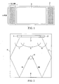
- FIG. 1 shows the exterior appearance of an array speaker system in accordance with a first embodiment of this invention.
- Reference numerals 1 and 2 designate array speakers, each of which has mxn speaker units arrayed in m rows and n columns (where m and n are integers of 2 or more); and reference numeral 3 designates a display having a screen or a large-size display screen.
- m is set to an integer of 6 or more
- n is set to an integer of 5 or more, whereby each of the array speakers 1 and 2 is preferably formed in a vertically elongated shape. That is, in the present embodiment, the first array speaker 1 and the second array speaker 2, each of which has a vertically elongated shape, are arranged at the left side and the right side of the display 3; thus, it is possible to realize a superior design.
- FIG. 2 diagrammatically shows a sound field realizing multi-channel reproduction using the array speaker system of the first embodiment shown in FIG. 1 . It performs 5.1 channel reproduction, for example.
- FIG. 2 is an illustration of a listening room in a plan view, wherein reference numeral 4 designates a listener; reference numeral 5 designates a left-side wall surface; reference numeral 6 designates a rear-side wall surface; and reference numeral 7 designates a right-side wall surface.
- reproduction for a main left channel (L), a center channel (C), and a surround left channel (SL) is allocated to the first array speaker 1 arranged at the left side of the display 3; and reproduction for a main right channel (R), a center channel (C), and a surround main right channel (R) is allocated to the second array speaker 2 arranged at the right side of the display 3.
- a Bessel array method in which the array speakers 1 and 2 are each driven with weights corresponding to weight coefficients based on a Bessel function is applied to the three channels lying in front of the listener 4, i.e., the aforementioned channels C, L, and R, whereby it is possible to realize spherical sound emission characteristics as shown in FIG. 2 .
- the sound beams emitted from the array speakers 1 and 2 respectively are reflected on prescribed walls and ceiling so as to make it possible for the listener 4 to hear sound virtually emitted from the rear side. That is, the sound beam of the SR channel emitted from the first array speaker 1 is firstly directed to the left-side wall surface 5; then, it is reflected on the wall surface 5; next, it is reflected on the ceiling (not shown); furthermore, it is reflected on the rear-side wall surface 6; thereafter, it reaches the rear-left portion of the head of the listener 4.
- the sound beam of the SR channel emitted from the second array speaker 2 is firstly directed to the right-side wall surface 7; then, it is reflected on the wall surface 7, ceiling, and wall surface 6 in turn; thereafter, it reaches the rear-right portion of the head of the listener 4.
- the present embodiment it is possible to realize spherical sound emission characteristics with respect to the three channels in front of the listener 4, i.e., the channels L, R, and C; hence, it is possible to realize natural audio reproduction without causing limitation to listening position.
- components of sound beams are effectively used with respect to the surround channels SL and SR regarding the rear side of the listener 4; hence, it is possible to realize audio reproduction at the rear side of the listener 4.
- reference numerals 1-11 to 1-mn designate speaker units of mxn array forming the first array speaker 1; and reference numeral 11 designates an A/D converter (ADC) for converting signals of the center channel (C) into digital data.
- Reference numerals 12-1 to 12-mn designate weighting means that are respectively arranged for the speaker units 1-11 to 1-mn so as to impart weights using weight coefficients CC 11 to CCmn based on a Bessel function to the center-channel signals.
- Reference numeral 13 designates an A/D converter (ADC) for converting signals of the main left channel (L) into digital data.
- Reference numerals 14-11 to 14-mn designate weighting means that are respectively arranged for the speaker units 1-11 to 1-mn so as to impart weights using weight coefficients CL11 to CLmn based on a Bessel function to the L-channel signals.
- Reference numeral 15 designates an A/D converter (ADC) for converting signals of the surround left channel (SL) into digital data.
- Reference numerals 16-11 to 16-mn designate delay means that are respectively arranged for the speaker units 1-11 to 1-mn so as to apply the corresponding delay values to the LS-channel signals, thus realizing beam-like concentration of sound in the surround left channel direction.
- Reference numerals 17-11 to 17-mn designate adders that are respectively arranged for the speaker units 1-11 to 1-mn so as to add output signals of the weighting means 12-11 to 12-mn, output signals of the weighting means 14-11 to 14-mn, and output signals of the delay means 16-11 to 16-mn together.
- Output signals of the adders 17-11 to 17-mn are converted into analog signals in D/A converters (DAC) 18-11 to 18-mn; furthermore, they are amplified in power amplifiers 19-11 to 19-mn; thereafter, they are supplied to the speaker units 1-11 to 1-mn respectively.
- DAC D/A converters
- addition signals that are produced by adding the C channel signals and L channel signals weighted based on the Bessel function to the SL channel signals applied with prescribed delay values are supplied to the speaker units 1-11 to 1-mn constituting the first array speaker 1 as its drive signals.
- the same circuit constitution as the circuit constitution of FIG. 3 arranged for the first array speaker 1 is arranged for the second array speaker 2. That is, the circuit constitution of FIG. 3 can be modified as shown in the reference symbols in parentheses so as to realize the circuit constitution for the second array speaker 2, wherein the L channel is replaced with the R channel, and the SL channel is replaced with the SR channel.
- signals of respective channels are converted into digital data in the A/D converters (ADC) 11, 13, and 15; then, the digital data are subjected to weighting and delay processing; thereafter, they are added together, but it is possible to perform signal processing in an analog manner without performing digitization. That is, analog signals can be directly subjected to weighting, delaying, and adding, whereby it is possible to omit the A/D converters (ADC) 11, 13, and 15 as well as the D/A converter (DAC) 18. Alternatively, it is possible to use digital amplifiers for the replacement of the amplifiers (AMP) 19 by omitting only the D/A converter (DAC) 18.
- FIG. 4 shows examples of weight coefficients based on a Bessel function, which are applied to the weighting means 12-11 to 12-mn and the weighing means 14-11 to 14-mn respectively.
- weight coefficients of J -7 (x1), J -6 (x1), J -4 (x1), J -3 (x1), J -2 (x1), J -2 (x1), J 0 (x1), J 1 (x1), J 1 (x1), J 3 (x1), J 4 (x1), J 5 (x1), J 6 (x1), and J 7 (x1) are used for fifteen speaker units vertically aligned; and weight coefficients J -2 (x2), J -1 (x2), J 0 (x2), J 1 (x2), and J 2 (x2) are used for five speaker units horizontally aligned.
- weight coefficients are similarly determined, with respect to the second array speaker 2.
- Delay values applied to the delay means 16-11 to 16-mn with respect to signals of the surround left channel (SL) will be described with reference to FIG. 5 .
- reference numerals 1-1 to 1-n designate n speaker units that are arrayed in a single line.
- a sound beam i.e., a concentrated flow of acoustic waves
- the focal point X serves as a virtual sound source.
- an angle of the sound beam reaching the focal point X is identical to an angle of the sound beam reaching the left-side wall surface 5 in FIG. 2 ; and the distance for the focal point X is identical to the distance for the setup position of the surround left channel (SL) speaker in FIG. 2 .
- the listener hears the sound as if the sound of the SL channel were emitted from the SL-channel speaker positioned at the focal point X.
- the second array speaker 2 arranged at the right side is controlled to emit a sound beam as described above.
- the number n of the speaker units in the columnar alignment is set to 5 or more.
- sound beams emitted from the array speakers are reflected on the wall surfaces and ceiling so as to realize the surround channel sound that is transmitted to the listener at the rear side. That is, it is possible to effectively use characteristics of the array speaker in which sound is transformed into a beam.
- the first embodiment describes the array speaker system constituted by the first array speaker arranged at the left side of the display 3 and the second array speaker 2 arranged at the right side of the display 3.
- This invention is not necessarily limited to an array speaker system having a divided arrangement of speakers.
- FIG. 6 shows the exterior appearance of an array speaker system in accordance with a second embodiment of this invention.
- the array speaker system of the second embodiment is constituted by a plurality of speaker units 21-11 to 21-jk, which are arrayed in j rows and k columns.
- j and k be set to integers of five or more.
- FIG. 7 is a circuit diagram showing the constitution of a drive circuit for driving the array speaker system of the second embodiment shown in FIG. 6 .
- reference numerals 22-11 to 22-jk designate multipliers that are respectively provided in connection with the speaker units 21-11 to 21-jk so as to apply prescribed gains to signals of the aforementioned center channel (C).
- Reference numerals 23-11 to 23-jk designate weighting means for applying weight coefficients based on a Bessel function to the C-channel signals.
- Reference numerals 24-11 to 24-jk designate multipliers that are provided in connection with the speaker units 21-11 to 21 jk respectively so as to apply prescribed gains to the L-channel signals.
- reference numerals 25-11 to 25-jk designate weighting means for applying weight coefficients based on a Bessel function to the L-channel signals.
- Reference numerals 26-11 to 26-jk designate multipliers that are provided in connection with the speaker units 21-11 to 21-jk respectively so as to apply prescribed gains to the R-channel signals.
- reference numerals 27-11 to 27-jk designate weighting means for applying weight coefficients based on a Bessel function to the R-channel signals.
- Reference numerals 28-11 to 28-jk designate multipliers that are provided in connection with the speaker units 21-11 to 21-jk respectively so as to apply prescribed gains to the SL-channel signals.
- reference numerals 29-11 to 29-jk designate delay means that apply prescribed delay values to the speaker units 21-11 to 21-jk in order to form a sound beam in response to the SL-channel signals.
- Reference numerals 30-11 to 30-jk designate multipliers that are provided in connection with the speaker units 21-11 to 21-jk respectively so as to apply prescribed gains to the SR-channel signals.
- reference numerals 31-11 to 31-jk designate delay means that apply prescribed delay values to the speaker units 21-11 to 21-jk in order to form a sound beam in response to the SR-channel signals.
- Reference numerals 32-11 to 32-jk designate adders that add together output signals of the weighing means 23-11 to 23-jk regarding the C-channel signals, output signals of the weighting means 25-11 to 25-jk regarding the L-channel signals, output signals of the weighting means 27-11 to 27-jk regarding the R-channel signals, output signals of the delay means 29-11 to 29-jk regarding the SL-channel signals, and output signals of the delay means 31-11 to 31-jk regarding the SR-channel signals.
- Reference numerals 33-11 to 33-jk designate amplifiers that respectively amplify output signals of the adders 32-11 to 32-jk so as to supply them to the speaker units 21-11 to 21-jk.
- three-channel signals in front of the listener i.e., C-channel signals, L-channel signals, and R-channel signals
- the speaker units 21-11 to 21-jk emit sounds in a Bessel-array-like manner.
- the speaker units 21-11 to 21-jk emit desired sound beams.
- the multipliers 22-11 to 22-jk, 24-11 to 24-jk, 26-11 to 26-jk, 28-11 to 28-jk, and 30-11 to 30-jk are provided to set up gains for the speaker units 21-11 to 21-jk with respect to signals of the C channel, L channel, R channel, SL channel, and SR channel.
- the multipliers 24-11 to 24-jk which are provided to apply gains to the speaker units 21-11 to 21-jk with respect to the L-channel signals, increase gains for the speaker units arrayed at the left-half side but decrease gains for the speaker units arrayed at the right-half side within the speaker units arrayed in a two-dimensional manner, for example.
- multipliers 26-11 to 26-jk which are provided to apply gains to the speaker units 21-11 to 21-jk with respect to the R-channel signals, increase gains for the speaker units arrayed at the right-half side but decrease gains for the speaker units arrayed at the left-half side within the speaker units arrayed in a two-dimensional manner, for example.
- Applied fields of this invention are not necessarily limited to multi-channel reproduction; hence, it is possible to perform audio reproduction using a Bessel array at the setup position of an array speaker and to perform audio reproduction using sound beams at another position.
- reference numeral 41 designates an array speaker that is constituted similarly to in the foregoing embodiments; and reference numeral 42 designates a ceiling to which the array speaker 41 is fixed.
- speaker units are driven by use of signals, which are weighted based on a Bessel function, at a position A entirely covering the whole space of a room in which the array speaker 41 is fixed to the ceiling 42.
- sound beams are emitted to focus on a certain position such as a corner B of the room other than the setup position of the array speaker 41 by use of delayed signals.
- the array speaker 41 it is possible to emit prescribed sound throughout the entirety of the room; and it is possible to emit sound beams towards a specific position such as the corner B of the room, for example. In this case, it is possible to emit reproduced sounds towards the positions A and B by use of the same signal; alternatively, it is possible to emit sounds reproduced by use of different signals.
- the array speaker system of this invention has a variety of effects and technical features as follows:
Landscapes
- Engineering & Computer Science (AREA)
- Physics & Mathematics (AREA)
- Acoustics & Sound (AREA)
- Signal Processing (AREA)
- Multimedia (AREA)
- Health & Medical Sciences (AREA)
- General Health & Medical Sciences (AREA)
- Otolaryngology (AREA)
- Obtaining Desirable Characteristics In Audible-Bandwidth Transducers (AREA)
- Stereophonic System (AREA)
- Circuit For Audible Band Transducer (AREA)
Claims (5)
- Array-Lautsprechersystem, das durch Anordnen einer Vielzahl von Lautsprechereinheiten (1-11 bis 1-mn) gebildet wird, wobei das Array-Lautsprechersystem Folgendes aufweist:Mittel (11, 13, 15) zum Eingeben von Signalen des Vorderseitenkanals (L, R, C) für die Anweisung der Reproduktion von Klängen auf einer Vorderseite eines Zuhörers (4) und Signalen des Rückseitenkanals (SL, SR) für die Anweisung der Reproduktion von Klängen auf einer Rückseite des Zuhörers (4); und Mittel (16-11 bis 16-mn; 17-11 bis 17-mn; 18-11 bis 18-mn; 19-11 bis 19-mn) zum Antreiben der Lautsprechereinheiten (1-11 bis 1-mn) in Bezug auf die Signale des Rückseitenkanals (SL, SR), die die Rückseitenkanalsignale einer vorbestimmten Verzögerungsverarbeitung aussetzen, um einen Klangstrahl zu bilden, der bei zumindest einer Klangreflektionsposition, wie beispielsweise einer Wandoberfläche oder einer Raumdecke, reflektiert wird, und dann die Rückseite des Zuhörers (4) erreicht;gekennzeichnet durch:Mittel (12-11 bis 12-mn; 14-11 bis 14-mn; 17-11 bis 17-mn; 18-11 bis 18-mn; 19-11 bis 19-mn) zum Antreiben der Lautsprechereinheiten (1-11 bis 1-mn) mit Gewichten unter Verwendung von Gewichtskoeffizienten, die auf einer Bessel-Funktion in Bezug auf die Signale des Vorderseitenkanals (L, R, C) basieren.
- Array-Lautsprechersystem gemäß Anspruch 1, welches durch eine Anzeige (3), einen ersten Array-Lautsprecher (1), der auf einer linken Seite der Anzeige (3) angeordnet ist, und einen zweiten Array-Lautsprecher (2), der auf einer rechten Seite der Anzeige (3) angeordnet ist, gebildet wird.
- Array-Lautsprechersystem gemäß Anspruch 2, wobei die Signale des Vorderseitenkanals (L, R, C) unter Verwendung eines Signals des linken Kanals (L), eines Signals des rechten Kanals (R) und eines Signals des mittleren Kanals (C) gebildet werden, und die Rückseitenkanalsignale (SL, SR) unter Verwendung eines Signals des linken Surround-Kanals (SL) und eines Signals des rechten Surround-Kanals (SR) gebildet werden,
und wobei in dem ersten Array-Lautsprecher (1), der auf der linken Seite der Anzeige (3) angeordnet ist, das Signal des linken Kanals (L) und das Signal des mittleren Kanals (C) einer Gewichtung ausgesetzt sind, und zwar unter Verwendung der Gewichtskoeffizienten, die auf der Bessel-Funktion basieren, und das Signal des linken Surround-Kanals (SL) einer Klangstrahlverarbeitung unterzogen wird,
und wobei in dem zweiten Array-Lautsprecher (2), der auf der rechten Seite der Anzeige (3) angeordnet ist, das Signal des rechten Kanals (R) und das Signal des mittleren Kanals (C) einer Gewichtung ausgesetzt sind, und zwar unter Verwendung der Gewichtskoeffizienten, die auf der Bessel-Funktion basieren, und das Signal des rechte Surround-Kanals (SR) einer Klangstrahlverarbeitung unterzogen wird. - Array-Lautsprechersystem gemäß Anspruch 1, wobei ein einzelner Array-Lautsprecher vor dem Zuhörer (4) angeordnet ist, und wobei in dem Array-Lautsprecher ein Signal des linken Kanals (L), ein Signal des rechten Kanals (R) und ein Signal des mittleren Kanals (C), die gemeinsam die Vorderseitenkanalsignale bilden, einer Gewichtung unter Verwendung der Gewichtskoeffizienten unterzogen werden, die auf der Bessel-Funktion basieren, und ein Signal des linken Surround-Kanals (SL) und ein Signal des rechten Surround-Kanals (SR), die beide die Rückseitenkanalsignale bilden, der Klangstrahlverarbeitung unterzogen werden.
- Array-Lautsprechersystem gemäß Anspruch 1, in dem die Vielzahl der Lautsprechereinheiten (21-11 bis 21-jk) in einer zweidimensionalen Weise ausgerichtet sind;
wobei das Mittel zum Antreiben der Lautsprechereinheiten in Bezug auf die Vorderseitenkanalsignale Folgendes aufweist:eine Vielzahl von ersten Multiplikatoren bzw. Verstärkern (22-11 bis 22-jk), die in Verbindung mit den Lautsprechereinheiten vorgesehen sind, um die Verstärkungen der Lautsprechereinheiten in Bezug auf ein Signal des mittleren Kanals (C) einzustellen, und zwar mit einer Vielzahl von ersten Gewichtungsmitteln (23-11 bis 23-jk), die angepasst sind, um Gewichte anzuwenden, die auf einer Bessel-Funktion basieren, und zwar auf die Ausgaben der ersten Verstärker;eine Vielzahl von zweiten Multiplikatoren bzw. Verstärkern (24-11 bis 24-jk), die in Verbindung mit den Lautsprechereinheiten vorgesehen sind, um die Verstärkungen für die Lautsprechereinheiten in Bezug auf ein Signal des linken Kanals (L) einzustellen, und zwar mit einer Vielzahl von zweiten Gewichtungsmitteln (25-11 bis 25-jk), die angepasst sind, um Gewichte anzuwenden, die auf der Basselfunktion basieren, und zwar auf die Ausgaben der zweiten Verstärker; undeine Vielzahl von dritten Multiplikatoren bzw. Verstärkern (26-11 bis 26-jk), die in Verbindung mit den Lautsprechereinheiten vorgesehen sind, um die Verstärkungen für die Lautsprechereinheiten in Bezug auf ein Signal des rechten Kanals (R) einzustellen, und zwar mit einer Vielzahl von dritten Gewichtungsmitteln (27-11 bis 27-jk), die angepasst sind, um Gewichte anzuwenden, die auf der Basselfunktion basieren, und zwar auf die Ausgaben der dritten Verstärker;wobei das Mittel zum Antreiben der Lautsprechereinheiten in Bezug auf die Rückseitenkanalsignale Folgendes aufweist:eine Vielzahl von vierten Multiplikatoren bzw. Verstärkern (28-11 bis 28-jk), die in Verbindung mit den Lautsprechereinheiten vorgesehen sind, um die Verstärkungen für die Lautsprechereinheiten in Bezug auf ein Signal des linken Surround-Kanals (SL) einzustellen, und zwar mit einer Vielzahl von ersten Verzögerungsmitteln (29-11 bis 29-jk), die angepasst ist, um die Verzögerungswerte einzustellen, die an die Lautsprechereinheiten für die Ausgaben der vierten Verstärker angepasst ist, um einen Strahl in Bezug auf das Signal des linken Surround-Kanals zu bilden; undeine Vielzahl von fünften Multiplikatoren bzw. Verstärkern (30-11 bis 30-jk), die in Verbindung mit den Lautsprechereinheiten vorgesehen sind, um die Verstärkungen für die Lautsprechereinheiten in Bezug auf das Signal des rechten Surround-Kanals (SR) einzustellen, und zwar mit einer Vielzahl von zweiten Verzögerungsmitteln (31-11 bis 31-jk), die angepasst sind, um die Verzögerungswerte einzustellen, die an die Lautsprechereinheiten angepasst sind, und zwar für die Ausgaben der fünften Verstärker, um einen Strahl in Bezug auf das Signal des rechten Surround-Kanals zu bilden;und wobei das Array-Lautsprechersystem ferner Folgendes aufweist:eine Vielzahl von Addiereinrichtungen (32-11 bis 32-jk), die in Verbindung mit den Lautsprechereinheiten vorgesehen sind, um die Ausgaben der ersten Gewichtungsmittel, der zweiten Gewichtungsmittel, der dritten Gewichtungsmittel, der ersten Verzögerungsmittel und der zweiten Verzögerungsmittel in Verbindung mit den Lautsprechereinheiten hinzuzufügen,eine Vielzahl von Leistungsverstärkern (33-11 bis 33-jk), die angepasst ist, um die Ausgaben der Addiereinrichtungen (32-11 bis 32-jk) zu verstärken, um die verstärkten Ausgaben der Addiereinrichtungen an die Lautsprechereinheiten zu liefern,wobei die zweiten Multiplikatoren bzw. Verstärker (24-11 bis 24-jk), die angepasst sind, um die Verstärkungen für die Lautsprechereinheiten in Bezug auf das Signal des linken Kanals (L) einzustellen, konfiguriert sind, um die Verstärkungen für die linke Hälfte der Lautsprechereinheiten zu erhöhen, während die Verstärkungen für die rechte Hälfte der Lautsprechereinheiten innerhalb der Lautsprechereinheiten, die in der zweidimensionalen Weise ausgerichtet sind, verringert werden, undwobei die Multiplikatoren bzw. Verstärker (26-11 bis 26-jk), die angepasst sind, um die Verstärkungen für die Lautsprechereinheiten in Bezug auf das Signal des rechten Kanals (R) einzustellen, konfiguriert sind, um die Verstärkungen für die linke Hälfte der Lautsprechereinheiten zu verringern, während die Verstärkungen für die rechte Hälfte der Lautsprechereinheiten innerhalb der Lautsprechereinheiten, die in der zweidimensionalen Weise ausgerichtet sind, erhöht werden.
Applications Claiming Priority (2)
| Application Number | Priority Date | Filing Date | Title |
|---|---|---|---|
| JP2003156766A JP4007254B2 (ja) | 2003-06-02 | 2003-06-02 | アレースピーカーシステム |
| PCT/JP2004/007911 WO2004107811A1 (ja) | 2003-06-02 | 2004-06-01 | アレースピーカーシステム |
Publications (3)
| Publication Number | Publication Date |
|---|---|
| EP1631118A1 EP1631118A1 (de) | 2006-03-01 |
| EP1631118A4 EP1631118A4 (de) | 2010-05-19 |
| EP1631118B1 true EP1631118B1 (de) | 2013-04-03 |
Family
ID=33487385
Family Applications (1)
| Application Number | Title | Priority Date | Filing Date |
|---|---|---|---|
| EP04745627A Expired - Lifetime EP1631118B1 (de) | 2003-06-02 | 2004-06-01 | Lautsprecherarray-System |
Country Status (5)
| Country | Link |
|---|---|
| US (1) | US20070019831A1 (de) |
| EP (1) | EP1631118B1 (de) |
| JP (1) | JP4007254B2 (de) |
| CN (1) | CN1833466B (de) |
| WO (1) | WO2004107811A1 (de) |
Families Citing this family (34)
| Publication number | Priority date | Publication date | Assignee | Title |
|---|---|---|---|---|
| JP4214834B2 (ja) * | 2003-05-09 | 2009-01-28 | ヤマハ株式会社 | アレースピーカーシステム |
| JP2005197896A (ja) | 2004-01-05 | 2005-07-21 | Yamaha Corp | スピーカアレイ用のオーディオ信号供給装置 |
| JP4251077B2 (ja) | 2004-01-07 | 2009-04-08 | ヤマハ株式会社 | スピーカ装置 |
| JP4501559B2 (ja) * | 2004-07-07 | 2010-07-14 | ヤマハ株式会社 | スピーカ装置の指向性制御方法およびオーディオ再生装置 |
| JP3915804B2 (ja) | 2004-08-26 | 2007-05-16 | ヤマハ株式会社 | オーディオ再生装置 |
| JP4779381B2 (ja) * | 2005-02-25 | 2011-09-28 | ヤマハ株式会社 | アレースピーカ装置 |
| GB2425029A (en) * | 2005-04-08 | 2006-10-11 | Giga Byte Tech Co Ltd | Surround sound system |
| US20080044050A1 (en) * | 2006-08-16 | 2008-02-21 | Gpx, Inc. | Multi-Channel Speaker System |
| USD597525S1 (en) | 2006-11-14 | 2009-08-04 | Sony Corporation | Modular entertainment system |
| JP2008258968A (ja) * | 2007-04-05 | 2008-10-23 | Mitsubishi Electric Engineering Co Ltd | アレイスピーカ |
| JP5034873B2 (ja) * | 2007-10-31 | 2012-09-26 | ヤマハ株式会社 | スピーカアレイシステム |
| JP5141390B2 (ja) * | 2008-06-19 | 2013-02-13 | ヤマハ株式会社 | スピーカ装置およびスピーカシステム |
| US8274611B2 (en) * | 2008-06-27 | 2012-09-25 | Mitsubishi Electric Visual Solutions America, Inc. | System and methods for television with integrated sound projection system |
| US8279357B2 (en) * | 2008-09-02 | 2012-10-02 | Mitsubishi Electric Visual Solutions America, Inc. | System and methods for television with integrated sound projection system |
| CN101527874B (zh) * | 2009-04-28 | 2011-03-23 | 张勤 | 一种动声声场系统 |
| CN102823273B (zh) | 2010-03-23 | 2015-12-16 | 杜比实验室特许公司 | 用于局域化感知音频的技术 |
| US10158958B2 (en) | 2010-03-23 | 2018-12-18 | Dolby Laboratories Licensing Corporation | Techniques for localized perceptual audio |
| US20120038827A1 (en) * | 2010-08-11 | 2012-02-16 | Charles Davis | System and methods for dual view viewing with targeted sound projection |
| EP2614658A1 (de) * | 2010-09-06 | 2013-07-17 | Cambridge Mechatronics Limited | Array-lautsprechersystem |
| WO2012122115A2 (en) * | 2011-03-04 | 2012-09-13 | Wan Jin Chung | Line speaker system and layout |
| US9324060B2 (en) * | 2011-05-10 | 2016-04-26 | International Business Machines Corporation | Displaying a plurality of calendar entries |
| JP5640911B2 (ja) | 2011-06-30 | 2014-12-17 | ヤマハ株式会社 | スピーカアレイ装置 |
| JP5728378B2 (ja) * | 2011-12-26 | 2015-06-03 | 株式会社竹中工務店 | 騒音低減装置 |
| US9721561B2 (en) * | 2013-12-05 | 2017-08-01 | Nuance Communications, Inc. | Method and apparatus for speech recognition using neural networks with speaker adaptation |
| CN105989845B (zh) | 2015-02-25 | 2020-12-08 | 杜比实验室特许公司 | 视频内容协助的音频对象提取 |
| JP6543957B2 (ja) | 2015-02-26 | 2019-07-17 | ヤマハ株式会社 | スピーカアレイ装置 |
| EP3128762A1 (de) * | 2015-08-03 | 2017-02-08 | Fraunhofer-Gesellschaft zur Förderung der angewandten Forschung e.V. | Soundbar |
| KR102631929B1 (ko) | 2016-02-24 | 2024-02-01 | 한국전자통신연구원 | 스크린 사이즈에 연동하는 전방 오디오 렌더링 장치 및 방법 |
| JP2017163432A (ja) * | 2016-03-10 | 2017-09-14 | ソニー株式会社 | 情報処理装置、情報処理方法、及び、プログラム |
| CN106792289A (zh) * | 2016-12-12 | 2017-05-31 | 深圳市艾特铭客科技有限公司 | 一种音响 |
| US10349199B2 (en) * | 2017-04-28 | 2019-07-09 | Bose Corporation | Acoustic array systems |
| CN112135227B (zh) * | 2020-09-30 | 2022-04-05 | 京东方科技集团股份有限公司 | 显示装置、发声控制方法及发声控制装置 |
| WO2022248043A1 (en) | 2021-05-27 | 2022-12-01 | Huawei Technologies Co., Ltd. | Audio device and method for producing a sound field |
| CN117098045B (zh) * | 2023-09-07 | 2024-04-12 | 广州市声拓电子有限公司 | 一种阵列扬声器实现方法 |
Family Cites Families (37)
| Publication number | Priority date | Publication date | Assignee | Title |
|---|---|---|---|---|
| NL221726A (de) | 1957-10-18 | |||
| US3308237A (en) * | 1963-05-31 | 1967-03-07 | Muter Company | Columnar loudspeaker system |
| US3873784A (en) * | 1973-03-29 | 1975-03-25 | Audio Arts Inc | Acoustic transducer |
| US4061876A (en) * | 1975-09-26 | 1977-12-06 | Jaffe Acoustics, Inc. | Electronic sound enhancing system |
| US4191852A (en) * | 1978-05-16 | 1980-03-04 | Shin-Shirasuna Electric Corporation | Stereophonic sense enhancing apparatus |
| US4218585A (en) * | 1979-04-05 | 1980-08-19 | Carver R W | Dimensional sound producing apparatus and method |
| JPS6425480A (en) | 1987-07-21 | 1989-01-27 | Matsushita Electric Industrial Co Ltd | Mos type semiconductor device |
| US5146507A (en) * | 1989-02-23 | 1992-09-08 | Yamaha Corporation | Audio reproduction characteristics control device |
| NL8900571A (nl) * | 1989-03-09 | 1990-10-01 | Prinssen En Bus Holding Bv | Electro-akoestisch systeem. |
| JPH04127700A (ja) * | 1990-09-18 | 1992-04-28 | Matsushita Electric Ind Co Ltd | 音像制御装置 |
| JPH0541897A (ja) * | 1991-08-07 | 1993-02-19 | Pioneer Electron Corp | スピーカ装置およびその指向性制御方法 |
| US5199075A (en) * | 1991-11-14 | 1993-03-30 | Fosgate James W | Surround sound loudspeakers and processor |
| DE69322805T2 (de) * | 1992-04-03 | 1999-08-26 | Yamaha Corp. | Verfahren zur Steuerung von Tonquellenposition |
| JP3205625B2 (ja) * | 1993-01-07 | 2001-09-04 | パイオニア株式会社 | スピーカ装置 |
| NL9401860A (nl) * | 1994-11-08 | 1996-06-03 | Duran Bv | Luidsprekersysteem met bestuurde richtinggevoeligheid. |
| US5809150A (en) * | 1995-06-28 | 1998-09-15 | Eberbach; Steven J. | Surround sound loudspeaker system |
| JP3826423B2 (ja) * | 1996-02-22 | 2006-09-27 | ソニー株式会社 | スピーカ装置 |
| JPH09322299A (ja) * | 1996-05-24 | 1997-12-12 | Victor Co Of Japan Ltd | 音像定位制御装置 |
| FI105522B (fi) * | 1996-08-06 | 2000-08-31 | Sample Rate Systems Oy | Järjestely kotiteatteri- tai muussa äänentoistolaitteistossa |
| US5789689A (en) * | 1997-01-17 | 1998-08-04 | Doidic; Michel | Tube modeling programmable digital guitar amplification system |
| JPH10304500A (ja) * | 1997-04-25 | 1998-11-13 | Victor Co Of Japan Ltd | 音場再生装置 |
| JP2000092578A (ja) * | 1998-09-09 | 2000-03-31 | Fujitsu Ltd | スピーカ装置 |
| US6546105B1 (en) * | 1998-10-30 | 2003-04-08 | Matsushita Electric Industrial Co., Ltd. | Sound image localization device and sound image localization method |
| JP2000267675A (ja) * | 1999-03-16 | 2000-09-29 | Sega Enterp Ltd | 音響信号処理装置 |
| JP4196509B2 (ja) * | 1999-12-27 | 2008-12-17 | ソニー株式会社 | 音場創出装置 |
| NZ502603A (en) * | 2000-02-02 | 2002-09-27 | Ind Res Ltd | Multitransducer microphone arrays with signal processing for high resolution sound field recording |
| US7003124B1 (en) * | 2000-05-30 | 2006-02-21 | Thiel Audio Products | System and method for adjusting frequency response characteristics of high-pass crossovers supplying signal to speakers used with subwoofers |
| JP2002010400A (ja) * | 2000-06-21 | 2002-01-11 | Sony Corp | 音響装置 |
| US7382888B2 (en) * | 2000-12-12 | 2008-06-03 | Bose Corporation | Phase shifting audio signal combining |
| CN100539737C (zh) | 2001-03-27 | 2009-09-09 | 1...有限公司 | 产生声场的方法和装置 |
| KR20030030451A (ko) * | 2001-10-11 | 2003-04-18 | 현대자동차주식회사 | 위상 조절 회로가 구비된 오디오 |
| US7116788B1 (en) * | 2002-01-17 | 2006-10-03 | Conexant Systems, Inc. | Efficient head related transfer function filter generation |
| JP4214834B2 (ja) * | 2003-05-09 | 2009-01-28 | ヤマハ株式会社 | アレースピーカーシステム |
| JP4007255B2 (ja) * | 2003-06-02 | 2007-11-14 | ヤマハ株式会社 | アレースピーカーシステム |
| US6937737B2 (en) * | 2003-10-27 | 2005-08-30 | Britannia Investment Corporation | Multi-channel audio surround sound from front located loudspeakers |
| JP2005197896A (ja) * | 2004-01-05 | 2005-07-21 | Yamaha Corp | スピーカアレイ用のオーディオ信号供給装置 |
| JP4501559B2 (ja) * | 2004-07-07 | 2010-07-14 | ヤマハ株式会社 | スピーカ装置の指向性制御方法およびオーディオ再生装置 |
-
2003
- 2003-06-02 JP JP2003156766A patent/JP4007254B2/ja not_active Expired - Fee Related
-
2004
- 2004-06-01 CN CN2004800150944A patent/CN1833466B/zh not_active Expired - Fee Related
- 2004-06-01 EP EP04745627A patent/EP1631118B1/de not_active Expired - Lifetime
- 2004-06-01 WO PCT/JP2004/007911 patent/WO2004107811A1/ja not_active Ceased
- 2004-06-01 US US10/558,542 patent/US20070019831A1/en not_active Abandoned
Also Published As
| Publication number | Publication date |
|---|---|
| EP1631118A4 (de) | 2010-05-19 |
| CN1833466B (zh) | 2011-12-28 |
| CN1833466A (zh) | 2006-09-13 |
| JP2004363695A (ja) | 2004-12-24 |
| EP1631118A1 (de) | 2006-03-01 |
| US20070019831A1 (en) | 2007-01-25 |
| WO2004107811A1 (ja) | 2004-12-09 |
| JP4007254B2 (ja) | 2007-11-14 |
Similar Documents
| Publication | Publication Date | Title |
|---|---|---|
| EP1631118B1 (de) | Lautsprecherarray-System | |
| EP1871143B1 (de) | Gruppenlautsprechervorrichtung | |
| CN101288338B (zh) | 使用线性阵列扬声器单元的音频回放方法和装置 | |
| US5764777A (en) | Four dimensional acoustical audio system | |
| US8194863B2 (en) | Speaker system | |
| EP0966179B1 (de) | Verfahren zur Synthese eines Audiosignals | |
| EP1631114B1 (de) | Lautsprechergruppierungssystem | |
| EP1694097A1 (de) | Array-lautsprechereinrichtung | |
| JP4920102B2 (ja) | 音響システム | |
| KR20040004566A (ko) | 사운드 필드를 생성하는 방법 및 장치 | |
| CN1761368B (zh) | 再现音频信号的方法和装置 | |
| JP2004179711A (ja) | スピーカ装置および音響再生方法 | |
| EP1890520B1 (de) | Array-lautsprechervorrichtung | |
| JPH021440B2 (de) | ||
| CN107333206B (zh) | 整体式音箱及其控制方法 | |
| Sayama et al. | Virtual sound source construction based on wave field synthesis using multiple parametric array loudspeakers | |
| KR20040031814A (ko) | 다중 채널을 위한 디지털 신호 처리 장치 및 그 방법 | |
| HK1013782A (en) | An acoustical audio system for producing three dimensional sound image |
Legal Events
| Date | Code | Title | Description |
|---|---|---|---|
| PUAI | Public reference made under article 153(3) epc to a published international application that has entered the european phase |
Free format text: ORIGINAL CODE: 0009012 |
|
| 17P | Request for examination filed |
Effective date: 20051201 |
|
| AK | Designated contracting states |
Kind code of ref document: A1 Designated state(s): DE FR GB |
|
| DAX | Request for extension of the european patent (deleted) | ||
| RBV | Designated contracting states (corrected) |
Designated state(s): DE FR GB |
|
| RAP1 | Party data changed (applicant data changed or rights of an application transferred) |
Owner name: YAMAHA CORPORATION |
|
| A4 | Supplementary search report drawn up and despatched |
Effective date: 20100419 |
|
| 17Q | First examination report despatched |
Effective date: 20110520 |
|
| GRAP | Despatch of communication of intention to grant a patent |
Free format text: ORIGINAL CODE: EPIDOSNIGR1 |
|
| GRAS | Grant fee paid |
Free format text: ORIGINAL CODE: EPIDOSNIGR3 |
|
| GRAA | (expected) grant |
Free format text: ORIGINAL CODE: 0009210 |
|
| AK | Designated contracting states |
Kind code of ref document: B1 Designated state(s): DE FR GB |
|
| REG | Reference to a national code |
Ref country code: GB Ref legal event code: FG4D |
|
| REG | Reference to a national code |
Ref country code: DE Ref legal event code: R096 Ref document number: 602004041583 Country of ref document: DE Effective date: 20130529 |
|
| PLBE | No opposition filed within time limit |
Free format text: ORIGINAL CODE: 0009261 |
|
| STAA | Information on the status of an ep patent application or granted ep patent |
Free format text: STATUS: NO OPPOSITION FILED WITHIN TIME LIMIT |
|
| 26N | No opposition filed |
Effective date: 20140106 |
|
| REG | Reference to a national code |
Ref country code: DE Ref legal event code: R097 Ref document number: 602004041583 Country of ref document: DE Effective date: 20140106 |
|
| REG | Reference to a national code |
Ref country code: FR Ref legal event code: PLFP Year of fee payment: 12 |
|
| PGFP | Annual fee paid to national office [announced via postgrant information from national office to epo] |
Ref country code: GB Payment date: 20150527 Year of fee payment: 12 Ref country code: DE Payment date: 20150527 Year of fee payment: 12 |
|
| PGFP | Annual fee paid to national office [announced via postgrant information from national office to epo] |
Ref country code: FR Payment date: 20150608 Year of fee payment: 12 |
|
| REG | Reference to a national code |
Ref country code: DE Ref legal event code: R119 Ref document number: 602004041583 Country of ref document: DE |
|
| GBPC | Gb: european patent ceased through non-payment of renewal fee |
Effective date: 20160601 |
|
| REG | Reference to a national code |
Ref country code: FR Ref legal event code: ST Effective date: 20170228 |
|
| PG25 | Lapsed in a contracting state [announced via postgrant information from national office to epo] |
Ref country code: DE Free format text: LAPSE BECAUSE OF NON-PAYMENT OF DUE FEES Effective date: 20170103 Ref country code: FR Free format text: LAPSE BECAUSE OF NON-PAYMENT OF DUE FEES Effective date: 20160630 |
|
| PG25 | Lapsed in a contracting state [announced via postgrant information from national office to epo] |
Ref country code: GB Free format text: LAPSE BECAUSE OF NON-PAYMENT OF DUE FEES Effective date: 20160601 |