EP1631013B1 - Hauptstation und Nebenstation in einem geschalteten Datennetzwerk sowie ein Verfahren zum Übertragen von Daten in einem solchen Netzwerk - Google Patents
Hauptstation und Nebenstation in einem geschalteten Datennetzwerk sowie ein Verfahren zum Übertragen von Daten in einem solchen Netzwerk Download PDFInfo
- Publication number
- EP1631013B1 EP1631013B1 EP05016053A EP05016053A EP1631013B1 EP 1631013 B1 EP1631013 B1 EP 1631013B1 EP 05016053 A EP05016053 A EP 05016053A EP 05016053 A EP05016053 A EP 05016053A EP 1631013 B1 EP1631013 B1 EP 1631013B1
- Authority
- EP
- European Patent Office
- Prior art keywords
- data
- output
- data packet
- network
- received
- Prior art date
- Legal status (The legal status is an assumption and is not a legal conclusion. Google has not performed a legal analysis and makes no representation as to the accuracy of the status listed.)
- Expired - Lifetime
Links
Images

Classifications
-
- H—ELECTRICITY
- H04—ELECTRIC COMMUNICATION TECHNIQUE
- H04L—TRANSMISSION OF DIGITAL INFORMATION, e.g. TELEGRAPHIC COMMUNICATION
- H04L12/00—Data switching networks
- H04L12/28—Data switching networks characterised by path configuration, e.g. LAN [Local Area Networks] or WAN [Wide Area Networks]
- H04L12/42—Loop networks
-
- H—ELECTRICITY
- H04—ELECTRIC COMMUNICATION TECHNIQUE
- H04L—TRANSMISSION OF DIGITAL INFORMATION, e.g. TELEGRAPHIC COMMUNICATION
- H04L12/00—Data switching networks
- H04L12/28—Data switching networks characterised by path configuration, e.g. LAN [Local Area Networks] or WAN [Wide Area Networks]
- H04L12/40—Bus networks
- H04L2012/40208—Bus networks characterized by the use of a particular bus standard
- H04L2012/40221—Profibus
-
- H—ELECTRICITY
- H04—ELECTRIC COMMUNICATION TECHNIQUE
- H04L—TRANSMISSION OF DIGITAL INFORMATION, e.g. TELEGRAPHIC COMMUNICATION
- H04L12/00—Data switching networks
- H04L12/64—Hybrid switching systems
- H04L12/6418—Hybrid transport
- H04L2012/6445—Admission control
- H04L2012/6448—Medium Access Control [MAC]
- H04L2012/6454—Random, e.g. Ethernet
-
- H—ELECTRICITY
- H04—ELECTRIC COMMUNICATION TECHNIQUE
- H04L—TRANSMISSION OF DIGITAL INFORMATION, e.g. TELEGRAPHIC COMMUNICATION
- H04L12/00—Data switching networks
- H04L12/64—Hybrid switching systems
- H04L12/6418—Hybrid transport
- H04L2012/6445—Admission control
- H04L2012/6459—Multiplexing, e.g. TDMA, CDMA
-
- H—ELECTRICITY
- H04—ELECTRIC COMMUNICATION TECHNIQUE
- H04L—TRANSMISSION OF DIGITAL INFORMATION, e.g. TELEGRAPHIC COMMUNICATION
- H04L12/00—Data switching networks
- H04L12/64—Hybrid switching systems
- H04L12/6418—Hybrid transport
- H04L2012/6464—Priority
Definitions
- the invention relates to a main station and a substation in a network z.
- a fieldbus network and, in particular, receiving external data and sending data provided internally to the device over the network.
- the invention further relates to a method for transmitting data in a network.
- Data networks typically include a main station and one or more substations interconnected by point-to-point links.
- the main station and the slave station can form a ring network, the main station via a unidirectional network connection to a data input of the first slave station, a data output of the first slave station with a data input of a second slave station, a data output of the second slave station with a data input of a third slave station, etc. are connected.
- the data output of the last substation is connected to a data input of the main station.
- a network topology may be provided which is linear, with the main station and the slave stations being connected to each other via network connections having two channels for the forward and reverse directions.
- the main characteristic of data networks is that the data received in the secondary stations are passed on via a repeater, wherein, as required, the time of handover to the reception can be delayed and the received data is provided in whole or in part for further processing and evaluation in the substation become.
- the transmission of the data can be done, for example, in data packets.
- the communication on a data network thus formed may be, for example, random, that is, the communication time when a station outputs a data packet to the data network through its data output is not fixed. In doing so, each station can send the data packet via its data output at any time. Since in such an IP network protocol (Internet Protocol), the network adapters at their data input output data packets usually directly through the repeater to the data output, it may come to the beginning of a transmission of a data packet to superimpositions of two data packets when of sending an external data packet is received. This can not be interpreted by a subsequent network participant.
- IP network protocol Internet Protocol
- a time range may be provided which is referred to as a real-time channel and are transmitted on the data packets in an orderly sequence, wherein a time-defined time window is assigned in at least one of the data packets of a respective slave station, so that the slave station the respective data assigned to it can be read from the data packet.
- a time window is reserved for the slave station, in which the slave station can insert data, while the slave station forwards the received data packet to its data output.
- the data network is constructed between at least two subscribers, wherein the data is transmitted in at least one transmission cycle with adjustable time duration and each transmission cycle is divided into at least a first range for transmitting real-time critical data and at least a second range for transmitting non real-time critical data.
- From the DE 34 13 144 A1 is a digital local communication system known.
- the stations in communication with each station are connected to a transmitting and parallel to a receiving line with the same direction or oppositely directed message flow.
- a network station for a data network for receiving external data and for transmitting data provided internally.
- the network station has a repeater to output an external data packet received at the data input at a data output.
- An initial data provision unit uses the data output to generate an internal data packet generated from the provided data.
- a control unit is connected to the switching device in order to block the output of the received external data packet via the data output in a first operating mode when the internal data packet is output by means of the data transmission unit.
- the output of the received external data packet by means of the repeater via the data output is permitted if no data packet is output via the first data supply unit.
- each of the network stations is ensured via the data network that when the network station transmits an internal data packet, the received external data packet is not forwarded.
- the internal data packet with the provided data there is no overlapping of external and internal data packets. which would lead to an illegibility of the data contained therein.
- the invention thus relates to a switched data network, in which context means that via a switching device according to the invention or according to the inventive method, the data path between the respective data input and data output - as described above - switchable, i. to open and interrupt or block is.
- switched data networks and repeater networks are known;
- the switched Ethernet technology is also referred to as a switched data network, but may differ from a data network connected in the sense of the invention.
- a real-time, based on the Ethernet standard data network can be created - especially for data networks with repeaters that just do not have a switching function in the sense of switched Ethernet (in this case, the invention offers the advantage that cheap and fast repeaters can be used and yet the overlay of packets can be reliably prevented).
- control unit may control the switching device such that in the first operating mode, the output of the received external data packet is blocked by means of the repeater via the data output until the received external data packet is terminated.
- the control unit operates cyclically during a first time period in the first operating mode and during a second time period in a second operating mode.
- a second data providing unit for sending provided data is provided.
- the control unit is connected to the switching means for alternately connecting the data output to the repeater and the second data providing unit in the second mode of operation such that a portion of a particular external data packet received at the data input is output from the repeater at the data output and provided data at a timed, the network station associated position of the particular data packet are inserted into the data packet.
- the network station can be used in a data network having two temporally defined communication channels.
- an IP communication channel is provided in the operating mode in which an incoming external data packet at a data input is not forwarded, if at this time an internal data packet is sent with data provided in the network device.
- a test data unit may be provided for receiving, at least in the second operating mode, the received external data packet from the input terminal and the data provided from the second data transmitting unit, and a check data to generate, wherein the control unit controls the switching device so that the test data is added to the received data packet at a further timely position of the received data packet.
- a method of receiving external data and sending data provided within the device to a data network comprises the steps of providing an internal data packet comprising the intra-device provided data, outputting the internal data packet via a data output, blocking the output of an external data packet received over the data network as long as the provided internal data packet is output to the data network becomes.
- the outputting of the received external data packet to the data network is blocked until the end of the output of the provided internal data packet until the received external data packet has ended. In this way it can be prevented that only a back part of a received external data packet is forwarded in the data network, which could possibly be interpreted incorrectly by a network station.
- the first operating mode forms an IP communication channel and the second operating mode forms a real-time communication channel
- the second operating mode comprising the following steps: sending a part of a specific received data packet via the data network; Insert the provided internal data at a timed position into the particular data packet.
- the provided data can be in a time window a predetermined data packet are inserted in the real-time communication channel, whereby the received data packet is filled with data, which are further transmitted over the data network.
- the steps may be performed: determining a check date from the particular received external data packet and the provided data and inserting the check date at a further timed position into the received external data packet.
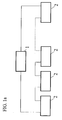
- FIGS. 1a and 1b show two possible network topologies for a data network, eg for a fieldbus network.
- a main station 1 communicates with substations 2 via point-to-point connections, the main station 1 having a data connection to a data input of a first substation, a data output of the first substation to a data input of a second substation, a data output of the second substation having a data input of a third substation, etc.
- the data output of a last slave station communicates with a data input of the master station 1, so that a ring network is formed.
- a data transmitted by the main station 1 is received by the first slave station 2 and forwarded via its data output to the next slave station until the data packet from the last slave station is returned to the main station 1 again.
- the handover of a data packet received at a data input of a slave station 2 is generally carried out via repeaters (not shown) in the respective slave station 2.
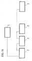
- FIG. 1b An alternative network construction is in Fig. 1b shown.
- the main station 1 and the secondary stations 2 are arranged in a line, wherein the secondary stations with respect to the main station 1 with the previous secondary station 2 and with the subsequent secondary station 2 can communicate in a bidirectional manner.
- a datum which for example receives a slave station 2 from its preceding slave station, is likewise forwarded there via a repeater to the following slave station and vice versa.
- a communication cycle comprises a first channel K1, a real-time communication channel, and a second channel K2, an IP communication channel.
- the real-time communication channel and the IP communication channel are successively occupied in temporal change as the second or first operating mode of main and auxiliary stations 1, 2 of the network formed therewith.
- the main station 1 transmits data packets in which respective time slots assigned to the respective secondary station 2 contain corresponding data assigned to the respective slave station 2.
- each of the secondary stations 2 is able to insert data on a time slot reserved and assigned to it, and thus to change the data packet as it is passed on.
- the master station 1 receives the modified data packet and then evaluates the received data packet modified by the slave stations 2 and, by assigning the data contained in the respective time slot to the respective slave station 2 receive the corresponding data from the slave station 2.
- the network stations can essentially communicate with each other at random.
- Each of the network stations can send a data packet with data to be sent if the respective network station does not receive a data packet at its data input.
- the secondary stations 2 are switched in the IP communication channel such that in principle an incoming external data packet at the data input is amplified via a repeater and output at the data output.
- data is inserted into the data packet transmitted via the repeater, but without buffering or otherwise delaying the received and forwarded external data packet. Such a setting may result in invalid data during the IP communication channel.
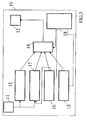
- the Fig. 3 shows by way of example a network station for constructing an annular network topology, as shown in FIG Fig. 1a is shown.
- the network station 10 has a data input interface 11 via which data can be received by the data network.
- a data output interface 12 is provided, via which data can be output to the data network in the next network station.
- Connected to the data input interface 11 is a repeater 13, which amplifies the received external data and forwards it to a first input of a multiplexer 14.
- a first data providing unit 15 and a second data providing unit 16 are provided.
- the first data providing unit 15 is designed so that it forms an internal data packet from the provided data during the IP communication channel, ie during the time window in which the network subscribers can arbitrarily send data packets.
- the second data providing unit 16 supplies the provided data in a form in which it can be inserted into a time slot in an external data packet received at the data input interface 11 during the real-time communication channel.
- An output of the second data providing unit 16 is connected both to a third input of the multiplexer 14 and to a first input of a test data generation unit 17.
- a second input of the test data generation unit 17 is connected to the data input interface 11.
- the check data generation unit 17 calculates a new check date from that at the data input interface 11 received external data packet and based on the provided data to be inserted and outputs the check data to a second input of the multiplexer 14.
- the multiplexer 14, the first data providing unit 15 and the second data providing unit 16 are connected to a control unit 18, which takes over the control of the communication cycle. If the network device 10 is in the first mode of operation, i. within the time range of the IP communication channel, the multiplexer 14 is switched so that data packets received at the data input interface 11 are forwarded via the repeater 13 to the data output interface 12. If there are internal data in the network station 10 that are to be sent over the data network, the provided data are passed to the first data providing unit 15, which forms an internal data packet from the provided data. As long as the network or the network device 10 is in the first operating mode, the control unit 18 first checks whether a data packet is currently being received at the data input interface 11.
- the control unit 18 controls the first data providing unit 15 to output the internal data packet formed from the provided data to the multiplexer 14. At substantially the same time, the multiplexer 14 is switched so that the first data providing unit 15 is connected to the data output interface 12. Meet during the transmission of the data packet through the first data supply unit 15 a data packet at the data input interface 11, the control unit 18 controls the repeater 13 so that it does not forward the received data packet but discards.
- the control unit After the end of the transmission of the internal data packet by the first data providing unit 15, the control unit switches the multiplexer 14 such that the repeater 13 is again in communication with the data output interface 12. Since it may happen that a back part of a data packet received via the data input interface 11 would be forwarded via the repeater 13 and the multiplexer 14 to the data output interface 12, the control unit 18 may first leave the multiplexer 14 designed such that the first data providing unit 15 remains in communication with the data output interface 12. This has the advantage that a back section of a data packet that would not be interpretable by another network participant would not be sent by the network station 10.
- the control unit 18 switches the multiplexer 14 such that the output of the repeater 13 is connected to the data output interface 12.
- subsequent received data packets can be forwarded from the data input interface 11 to the data output interface 12. If an internal data packet formed from the provided data was sent during the IP communication channel and then the control unit 18 determines that a remainder of an external data packet is received via the data input interface 11, the control unit 18 controls the first data providing unit 15 so-called Idle signals are sent.
- the control unit 18 switches between the first, second and third inputs of the multiplexer 14 during a data packet.
- one or more first data packets are first sent, with which the main station 1 transmits data to the secondary stations 2.
- These data packets contain multiple timeslots that represent the data for the time slot associated respective substation 2 included.
- the main station 1 sends only placeholder data at which the secondary stations 2 can insert data, each secondary station 2 being assigned a specific time slot, ie a predetermined position in the data packet.
- the multiplexer 14 is initially controlled so that the repeater 13 is connected to the data output interface 12.
- the repeater 13 While receiving one of the first data packets, the repeater 13 analyzes the received data and may provide the data extracted from the first data packet to the network station. Even when receiving the second data packets of the real-time communication channel, the repeater 13 remains initially connected to the data output interface 12 until the time at which the time window begins, which is associated with the respective network station 10. Then, the multiplexer 14 is switched so that the second data providing unit 16 is connected to the data output interface 12 and can insert the provided internal data into the external data packet during the time window. After outputting the internal data provided by the second data providing unit 16, the control unit switches the multiplexer 14 back again, so that the repeater 13 outputs the remaining data of the external second data packet to the data output interface 12.
- the second data providing unit 16 also makes the provided data available to the test data generation unit 17, which also receives the second data packet.
- the test data generation unit generates test data added to the second data packet. For this purpose, a corresponding time position of the data packet of the multiplexer 14 is switched by the control unit 18 so that the test data generation unit 17 via the multiplexer 14 to the data output interface 12 is created. Then, the check data is sent and the control unit then switches the multiplexer 14 so that the repeater 13 is again connected to the data output interface 12.
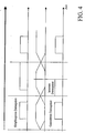
- Fig. 4 the timing of successive data packets during an IP communication channel is shown when an internal data packet is to be sent by the network station 10.
- the repeater amplifies the received data packet and outputs it via the data output interface 12.
- it is first checked that no external data packet is received via the data input interface 11. If this is the case, as in the second part of the diagram of the Fig. 4 shown, the internal data packet sent. If, after the end of the transmission of the internal data packet, it is detected that an external data packet is received via the data input interface, this is not output at the data output interface 12 until this external data packet has ended and only then, as in the third part of the diagram Fig. 4 shown, a next received external data packet via the data output interface 12 forwarded to the next network station.
Landscapes
- Engineering & Computer Science (AREA)
- Computer Networks & Wireless Communication (AREA)
- Signal Processing (AREA)
- Data Exchanges In Wide-Area Networks (AREA)
- Small-Scale Networks (AREA)
- Communication Control (AREA)
- Circuits Of Receivers In General (AREA)
- Mobile Radio Communication Systems (AREA)
Applications Claiming Priority (1)
| Application Number | Priority Date | Filing Date | Title |
|---|---|---|---|
| DE102004041093A DE102004041093A1 (de) | 2004-08-24 | 2004-08-24 | Hauptstation und Nebenstation in einem Netzwerk sowie ein Verfahren zum Übertragen von Daten in einem Netzwerk |
Publications (2)
| Publication Number | Publication Date |
|---|---|
| EP1631013A1 EP1631013A1 (de) | 2006-03-01 |
| EP1631013B1 true EP1631013B1 (de) | 2008-09-03 |
Family
ID=35407061
Family Applications (1)
| Application Number | Title | Priority Date | Filing Date |
|---|---|---|---|
| EP05016053A Expired - Lifetime EP1631013B1 (de) | 2004-08-24 | 2005-07-23 | Hauptstation und Nebenstation in einem geschalteten Datennetzwerk sowie ein Verfahren zum Übertragen von Daten in einem solchen Netzwerk |
Country Status (7)
| Country | Link |
|---|---|
| US (2) | US7680119B2 (enExample) |
| EP (1) | EP1631013B1 (enExample) |
| JP (1) | JP2006067590A (enExample) |
| AT (1) | ATE407499T1 (enExample) |
| DE (2) | DE102004041093A1 (enExample) |
| DK (1) | DK1631013T3 (enExample) |
| ES (1) | ES2313160T3 (enExample) |
Families Citing this family (10)
| Publication number | Priority date | Publication date | Assignee | Title |
|---|---|---|---|---|
| DE102006004339A1 (de) | 2006-01-30 | 2007-08-02 | Robert Bosch Gmbh | Redundantes Kommunikationsnetzwerk |
| US8682357B2 (en) | 2006-05-02 | 2014-03-25 | Intellectual Ventures Holding 81 Llc | Paging in a wireless network |
| CZ303038B6 (cs) * | 2010-04-06 | 2012-03-07 | Vysoké ucení technické v Brne | Zpusob distribuce dat smyckou a distribucní blok smycky k provádení tohoto zpusobu |
| DE102010031798B4 (de) * | 2010-07-20 | 2021-11-11 | Robert Bosch Gmbh | Automatisierungsverbund und Verfahren zu dessen Betrieb |
| DE102010035771A1 (de) * | 2010-08-19 | 2012-02-23 | Pilz Gmbh & Co. Kg | Verfahren zur Vergabe von Teilnehmeradressen an Busteilnehmer eines busbasierten Steuerungssystems |
| DE102012010851A1 (de) | 2012-05-31 | 2013-12-05 | Robert Bosch Gmbh | Feldbusnetzwerk aufweisend zwei Hauptteilnehmer und wenigstens einen Nebenteilnehmer |
| DE102012020763A1 (de) | 2012-10-23 | 2014-04-24 | Robert Bosch Gmbh | Kommunikationsnetzwerk aufweisend zwei Hauptteilnehmer und wenigstens einen Nebenteilnehmer mit zweikanaliger Übertragung |
| DE102014201373A1 (de) | 2014-01-27 | 2015-07-30 | Robert Bosch Gmbh | Verfahren zum Betreiben eines redundanten Kommunikationsnetzwerkes |
| EP3104558B1 (de) * | 2015-06-11 | 2018-12-12 | Airbus Defence and Space GmbH | Netzwerkinterface, netzwerk und verfahren zur datenübertragung innerhalb des netzwerkes |
| DE102015225046A1 (de) | 2015-12-14 | 2017-06-14 | Robert Bosch Gmbh | Verfahren zum Betreiben eines Kommunikationsnetzwerks |
Family Cites Families (14)
| Publication number | Priority date | Publication date | Assignee | Title |
|---|---|---|---|---|
| US3810100A (en) * | 1971-12-16 | 1974-05-07 | Collins Radio Co | Looped direct switching system |
| CH550521A (de) * | 1972-07-04 | 1974-06-14 | Hasler Ag | Verfahren zur nachrichtenuebertragung zwischen teilnehmerstellen. |
| DE3413144A1 (de) * | 1984-04-07 | 1985-10-17 | Licentia Patent-Verwaltungs-Gmbh, 6000 Frankfurt | Digitales lokales kommunikationssystem mit der logischen struktur einer schleife |
| JPS63267040A (ja) * | 1987-04-24 | 1988-11-04 | Mitsubishi Rayon Co Ltd | ル−プネツトワ−クにおけるデ−タ伝送方法及びこれに用いるインタ−フエイス |
| US5412756A (en) * | 1992-12-22 | 1995-05-02 | Mitsubishi Denki Kabushiki Kaisha | Artificial intelligence software shell for plant operation simulation |
| US5896384A (en) * | 1997-02-28 | 1999-04-20 | Intel Corporation | Method and apparatus for transferring deterministic latency packets in a ringlet |
| JP2000174810A (ja) * | 1998-12-02 | 2000-06-23 | Matsushita Electric Ind Co Ltd | 伝送システム、インターフェース装置および伝送方法 |
| CA2255418C (en) * | 1998-12-07 | 2003-01-21 | Pmc-Sierra Ltd. | Ring interface and ring network bus flow control system |
| US6266748B1 (en) * | 1999-03-30 | 2001-07-24 | Integrated Device Technology, Inc. | Priority encoding for FIFO memory devices that interface multiple ports to a data receiving device |
| US6530052B1 (en) * | 1999-12-29 | 2003-03-04 | Advanced Micro Devices, Inc. | Method and apparatus for looping back a current state to resume a memory built-in self-test |
| JP2002091933A (ja) * | 2000-09-20 | 2002-03-29 | Hitachi Ltd | プロセッサシステム |
| US6970939B2 (en) * | 2000-10-26 | 2005-11-29 | Intel Corporation | Method and apparatus for large payload distribution in a network |
| DE10058524A1 (de) * | 2000-11-24 | 2002-06-13 | Siemens Ag | System und Verfahren zur parallelen Übertragung von echtzeitkritischen und nicht echtzeitkritischen Daten über schaltbare Datennetze, insbesondere Ethernet |
| CN1701584A (zh) * | 2003-07-23 | 2005-11-23 | 三星电子株式会社 | 用于在网际协议系统中产生访问终端的网际协议地址并发送用于产生网际协议地址的消息的方法和系统 |
-
2004
- 2004-08-24 DE DE102004041093A patent/DE102004041093A1/de not_active Ceased
-
2005
- 2005-07-23 AT AT05016053T patent/ATE407499T1/de active
- 2005-07-23 DK DK05016053T patent/DK1631013T3/da active
- 2005-07-23 ES ES05016053T patent/ES2313160T3/es not_active Expired - Lifetime
- 2005-07-23 EP EP05016053A patent/EP1631013B1/de not_active Expired - Lifetime
- 2005-07-23 DE DE502005005243T patent/DE502005005243D1/de not_active Expired - Lifetime
- 2005-08-19 US US11/208,219 patent/US7680119B2/en not_active Expired - Fee Related
- 2005-08-24 US US11/210,930 patent/US20060045097A1/en not_active Abandoned
- 2005-08-24 JP JP2005243241A patent/JP2006067590A/ja active Pending
Also Published As
| Publication number | Publication date |
|---|---|
| DE102004041093A1 (de) | 2006-03-09 |
| ATE407499T1 (de) | 2008-09-15 |
| JP2006067590A (ja) | 2006-03-09 |
| US20060045097A1 (en) | 2006-03-02 |
| US7680119B2 (en) | 2010-03-16 |
| DK1631013T3 (da) | 2009-01-26 |
| DE502005005243D1 (de) | 2008-10-16 |
| ES2313160T3 (es) | 2009-03-01 |
| US20060045119A1 (en) | 2006-03-02 |
| EP1631013A1 (de) | 2006-03-01 |
Similar Documents
| Publication | Publication Date | Title |
|---|---|---|
| EP1453251B1 (de) | Echtzeit- und Nicht-Echtzeitverkehr in einem lokalen Netz | |
| AT507125B1 (de) | Multirouter für zeitgesteuerte kommunikationssysteme | |
| DE69117106T2 (de) | Verfahren zum Kontrollieren der Einfügung von Stationen in einem Netzwerk mit optischen Fasern (FDDI-Netzwerk) | |
| DE69829428T2 (de) | Zuweisung und dynamische Anpassung von zweiten, nicht eindeutigen Kennzeichnungen für isochrone Kommunikationen an eine Vielzahl von Stationen mittels asynchronischer Kommunikation | |
| EP1631013B1 (de) | Hauptstation und Nebenstation in einem geschalteten Datennetzwerk sowie ein Verfahren zum Übertragen von Daten in einem solchen Netzwerk | |
| EP3622692A1 (de) | Verfahren zur performanten datenübertragung in einem datennetz mit teilweise echtzeit-anforderungen und vorrichtung zur durchführung des verfahrens | |
| EP2961106A1 (de) | Netzwerk, kopf-teilnehmer und datenübertragungsverfahren | |
| EP3625627A1 (de) | Summenstreams für istzustände und steuersignale eines verteilten steuerungssystems | |
| EP0609177B1 (de) | Verfahren und Einrichtung zur bidirektionalen Informationsübertragung (Full-Duplex). | |
| DE19906867C1 (de) | Verfahren und Vorrichtung zur seriellen Datenübertragung | |
| EP0682422A2 (de) | Verfahren und Schaltungsanordnung zum Synchronisieren von redundant übertragenen Nachrichtenzellenströmen | |
| DE102004050416A1 (de) | Verfahren zur Synchronisation in einem redundanten Kommunikationssystem | |
| DE10004425A1 (de) | Netzwerk sowie Netzwerkteilnehmer, insbesondere Feldgerät, für ein derartiges Netzwerk | |
| EP1181790B1 (de) | Netzwerk sowie koppelgerät zur verbindung zweier segmente in einem derartigen netzwerk und netzwerkteilnehmer | |
| WO2009087090A1 (de) | Vorrichtung und verfahren zur wahlweisen umschaltung zweier master für zugeordnete slaves in einer logischen ringschaltung | |
| EP3744047B1 (de) | Teilnehmerstation für ein bussystem und verfahren zum senden einer nachricht mit unterschiedlichen bitraten in einem bussystem | |
| EP1540905A1 (de) | Verfahren zur übertragung von datentelegrammen in einem geschalteten, zyklischen kommunikationssystem | |
| EP1965549B1 (de) | Bussystem und Verfahren zum Betreiben des Bussystems | |
| EP2965560B1 (de) | Verfahren und netzwerkinfrastruktur zum redundanten übertragen von nachrichten in einem verteilten echtzeitsystem | |
| DE2849348C2 (enExample) | ||
| EP3664510A1 (de) | Wechsel des datenübertragungsweges ohne verlust von datenpaketen | |
| EP1353427B1 (de) | Redundante Übertragung von Schutzbefehlen zwischen Fernauslösegeräten | |
| DE4243441C1 (de) | Zeitmultiplex-Übertragungssystem | |
| DE4243442C1 (de) | Betriebsverfahren für ein Zeitmultiplex-Übertragungssystem | |
| DE4227736B4 (de) | Netzwerk mit einer Abzweig- und Kanalverteilungsvorrichtung |
Legal Events
| Date | Code | Title | Description |
|---|---|---|---|
| PUAI | Public reference made under article 153(3) epc to a published international application that has entered the european phase |
Free format text: ORIGINAL CODE: 0009012 |
|
| AK | Designated contracting states |
Kind code of ref document: A1 Designated state(s): AT BE BG CH CY CZ DE DK EE ES FI FR GB GR HU IE IS IT LI LT LU LV MC NL PL PT RO SE SI SK TR |
|
| AX | Request for extension of the european patent |
Extension state: AL BA HR MK YU |
|
| 17P | Request for examination filed |
Effective date: 20060901 |
|
| 17Q | First examination report despatched |
Effective date: 20061009 |
|
| AKX | Designation fees paid |
Designated state(s): AT BE BG CH CY CZ DE DK EE ES FI FR GB GR HU IE IS IT LI LT LU LV MC NL PL PT RO SE SI SK TR |
|
| GRAP | Despatch of communication of intention to grant a patent |
Free format text: ORIGINAL CODE: EPIDOSNIGR1 |
|
| RTI1 | Title (correction) |
Free format text: MAIN STATION AND AUXILIARY STATION IN A SWITCHED DATA NETWORK AND METHOD FOR TRANSMITTING DATA IN SUCH A NETWORK |
|
| GRAS | Grant fee paid |
Free format text: ORIGINAL CODE: EPIDOSNIGR3 |
|
| GRAA | (expected) grant |
Free format text: ORIGINAL CODE: 0009210 |
|
| AK | Designated contracting states |
Kind code of ref document: B1 Designated state(s): AT BE BG CH CY CZ DE DK EE ES FI FR GB GR HU IE IS IT LI LT LU LV MC NL PL PT RO SE SI SK TR |
|
| REG | Reference to a national code |
Ref country code: GB Ref legal event code: FG4D Free format text: NOT ENGLISH |
|
| REG | Reference to a national code |
Ref country code: CH Ref legal event code: EP |
|
| REG | Reference to a national code |
Ref country code: IE Ref legal event code: FG4D Free format text: LANGUAGE OF EP DOCUMENT: GERMAN |
|
| REF | Corresponds to: |
Ref document number: 502005005243 Country of ref document: DE Date of ref document: 20081016 Kind code of ref document: P |
|
| REG | Reference to a national code |
Ref country code: SE Ref legal event code: TRGR |
|
| REG | Reference to a national code |
Ref country code: DK Ref legal event code: T3 |
|
| PG25 | Lapsed in a contracting state [announced via postgrant information from national office to epo] |
Ref country code: LT Free format text: LAPSE BECAUSE OF FAILURE TO SUBMIT A TRANSLATION OF THE DESCRIPTION OR TO PAY THE FEE WITHIN THE PRESCRIBED TIME-LIMIT Effective date: 20080903 |
|
| PG25 | Lapsed in a contracting state [announced via postgrant information from national office to epo] |
Ref country code: FI Free format text: LAPSE BECAUSE OF FAILURE TO SUBMIT A TRANSLATION OF THE DESCRIPTION OR TO PAY THE FEE WITHIN THE PRESCRIBED TIME-LIMIT Effective date: 20080903 Ref country code: LV Free format text: LAPSE BECAUSE OF FAILURE TO SUBMIT A TRANSLATION OF THE DESCRIPTION OR TO PAY THE FEE WITHIN THE PRESCRIBED TIME-LIMIT Effective date: 20080903 Ref country code: SI Free format text: LAPSE BECAUSE OF FAILURE TO SUBMIT A TRANSLATION OF THE DESCRIPTION OR TO PAY THE FEE WITHIN THE PRESCRIBED TIME-LIMIT Effective date: 20080903 |
|
| REG | Reference to a national code |
Ref country code: ES Ref legal event code: FG2A Ref document number: 2313160 Country of ref document: ES Kind code of ref document: T3 |
|
| REG | Reference to a national code |
Ref country code: IE Ref legal event code: FD4D |
|
| PG25 | Lapsed in a contracting state [announced via postgrant information from national office to epo] |
Ref country code: BG Free format text: LAPSE BECAUSE OF FAILURE TO SUBMIT A TRANSLATION OF THE DESCRIPTION OR TO PAY THE FEE WITHIN THE PRESCRIBED TIME-LIMIT Effective date: 20081203 Ref country code: IE Free format text: LAPSE BECAUSE OF FAILURE TO SUBMIT A TRANSLATION OF THE DESCRIPTION OR TO PAY THE FEE WITHIN THE PRESCRIBED TIME-LIMIT Effective date: 20080903 |
|
| PG25 | Lapsed in a contracting state [announced via postgrant information from national office to epo] |
Ref country code: SK Free format text: LAPSE BECAUSE OF FAILURE TO SUBMIT A TRANSLATION OF THE DESCRIPTION OR TO PAY THE FEE WITHIN THE PRESCRIBED TIME-LIMIT Effective date: 20080903 Ref country code: PT Free format text: LAPSE BECAUSE OF FAILURE TO SUBMIT A TRANSLATION OF THE DESCRIPTION OR TO PAY THE FEE WITHIN THE PRESCRIBED TIME-LIMIT Effective date: 20090203 Ref country code: CZ Free format text: LAPSE BECAUSE OF FAILURE TO SUBMIT A TRANSLATION OF THE DESCRIPTION OR TO PAY THE FEE WITHIN THE PRESCRIBED TIME-LIMIT Effective date: 20080903 Ref country code: RO Free format text: LAPSE BECAUSE OF FAILURE TO SUBMIT A TRANSLATION OF THE DESCRIPTION OR TO PAY THE FEE WITHIN THE PRESCRIBED TIME-LIMIT Effective date: 20080903 Ref country code: IS Free format text: LAPSE BECAUSE OF FAILURE TO SUBMIT A TRANSLATION OF THE DESCRIPTION OR TO PAY THE FEE WITHIN THE PRESCRIBED TIME-LIMIT Effective date: 20090103 |
|
| PLBE | No opposition filed within time limit |
Free format text: ORIGINAL CODE: 0009261 |
|
| STAA | Information on the status of an ep patent application or granted ep patent |
Free format text: STATUS: NO OPPOSITION FILED WITHIN TIME LIMIT |
|
| PG25 | Lapsed in a contracting state [announced via postgrant information from national office to epo] |
Ref country code: EE Free format text: LAPSE BECAUSE OF FAILURE TO SUBMIT A TRANSLATION OF THE DESCRIPTION OR TO PAY THE FEE WITHIN THE PRESCRIBED TIME-LIMIT Effective date: 20080903 |
|
| 26N | No opposition filed |
Effective date: 20090604 |
|
| BERE | Be: lapsed |
Owner name: BOSCH REXROTH A.G. Effective date: 20090731 |
|
| PG25 | Lapsed in a contracting state [announced via postgrant information from national office to epo] |
Ref country code: MC Free format text: LAPSE BECAUSE OF NON-PAYMENT OF DUE FEES Effective date: 20090731 |
|
| REG | Reference to a national code |
Ref country code: CH Ref legal event code: PL |
|
| GBPC | Gb: european patent ceased through non-payment of renewal fee |
Effective date: 20090723 |
|
| PG25 | Lapsed in a contracting state [announced via postgrant information from national office to epo] |
Ref country code: CH Free format text: LAPSE BECAUSE OF NON-PAYMENT OF DUE FEES Effective date: 20090731 Ref country code: LI Free format text: LAPSE BECAUSE OF NON-PAYMENT OF DUE FEES Effective date: 20090731 |
|
| PG25 | Lapsed in a contracting state [announced via postgrant information from national office to epo] |
Ref country code: GB Free format text: LAPSE BECAUSE OF NON-PAYMENT OF DUE FEES Effective date: 20090723 Ref country code: PL Free format text: LAPSE BECAUSE OF FAILURE TO SUBMIT A TRANSLATION OF THE DESCRIPTION OR TO PAY THE FEE WITHIN THE PRESCRIBED TIME-LIMIT Effective date: 20080903 |
|
| PG25 | Lapsed in a contracting state [announced via postgrant information from national office to epo] |
Ref country code: BE Free format text: LAPSE BECAUSE OF NON-PAYMENT OF DUE FEES Effective date: 20090731 |
|
| PG25 | Lapsed in a contracting state [announced via postgrant information from national office to epo] |
Ref country code: GR Free format text: LAPSE BECAUSE OF FAILURE TO SUBMIT A TRANSLATION OF THE DESCRIPTION OR TO PAY THE FEE WITHIN THE PRESCRIBED TIME-LIMIT Effective date: 20081204 |
|
| PG25 | Lapsed in a contracting state [announced via postgrant information from national office to epo] |
Ref country code: LU Free format text: LAPSE BECAUSE OF NON-PAYMENT OF DUE FEES Effective date: 20090723 |
|
| PG25 | Lapsed in a contracting state [announced via postgrant information from national office to epo] |
Ref country code: HU Free format text: LAPSE BECAUSE OF FAILURE TO SUBMIT A TRANSLATION OF THE DESCRIPTION OR TO PAY THE FEE WITHIN THE PRESCRIBED TIME-LIMIT Effective date: 20090304 |
|
| PG25 | Lapsed in a contracting state [announced via postgrant information from national office to epo] |
Ref country code: TR Free format text: LAPSE BECAUSE OF FAILURE TO SUBMIT A TRANSLATION OF THE DESCRIPTION OR TO PAY THE FEE WITHIN THE PRESCRIBED TIME-LIMIT Effective date: 20080903 |
|
| PG25 | Lapsed in a contracting state [announced via postgrant information from national office to epo] |
Ref country code: CY Free format text: LAPSE BECAUSE OF FAILURE TO SUBMIT A TRANSLATION OF THE DESCRIPTION OR TO PAY THE FEE WITHIN THE PRESCRIBED TIME-LIMIT Effective date: 20080903 |
|
| PGFP | Annual fee paid to national office [announced via postgrant information from national office to epo] |
Ref country code: FR Payment date: 20110729 Year of fee payment: 7 Ref country code: DK Payment date: 20110725 Year of fee payment: 7 |
|
| PGFP | Annual fee paid to national office [announced via postgrant information from national office to epo] |
Ref country code: SE Payment date: 20110721 Year of fee payment: 7 Ref country code: ES Payment date: 20110728 Year of fee payment: 7 |
|
| PGFP | Annual fee paid to national office [announced via postgrant information from national office to epo] |
Ref country code: IT Payment date: 20110728 Year of fee payment: 7 Ref country code: NL Payment date: 20110725 Year of fee payment: 7 |
|
| REG | Reference to a national code |
Ref country code: NL Ref legal event code: V1 Effective date: 20130201 |
|
| REG | Reference to a national code |
Ref country code: SE Ref legal event code: EUG |
|
| REG | Reference to a national code |
Ref country code: DK Ref legal event code: EBP |
|
| REG | Reference to a national code |
Ref country code: FR Ref legal event code: ST Effective date: 20130329 |
|
| PG25 | Lapsed in a contracting state [announced via postgrant information from national office to epo] |
Ref country code: FR Free format text: LAPSE BECAUSE OF NON-PAYMENT OF DUE FEES Effective date: 20120731 Ref country code: NL Free format text: LAPSE BECAUSE OF NON-PAYMENT OF DUE FEES Effective date: 20130201 Ref country code: SE Free format text: LAPSE BECAUSE OF NON-PAYMENT OF DUE FEES Effective date: 20120724 |
|
| PG25 | Lapsed in a contracting state [announced via postgrant information from national office to epo] |
Ref country code: IT Free format text: LAPSE BECAUSE OF NON-PAYMENT OF DUE FEES Effective date: 20120723 |
|
| PG25 | Lapsed in a contracting state [announced via postgrant information from national office to epo] |
Ref country code: DK Free format text: LAPSE BECAUSE OF NON-PAYMENT OF DUE FEES Effective date: 20120731 |
|
| REG | Reference to a national code |
Ref country code: ES Ref legal event code: FD2A Effective date: 20131021 |
|
| PG25 | Lapsed in a contracting state [announced via postgrant information from national office to epo] |
Ref country code: ES Free format text: LAPSE BECAUSE OF NON-PAYMENT OF DUE FEES Effective date: 20120724 |
|
| PGFP | Annual fee paid to national office [announced via postgrant information from national office to epo] |
Ref country code: AT Payment date: 20140620 Year of fee payment: 10 |
|
| REG | Reference to a national code |
Ref country code: AT Ref legal event code: MM01 Ref document number: 407499 Country of ref document: AT Kind code of ref document: T Effective date: 20150723 |
|
| PG25 | Lapsed in a contracting state [announced via postgrant information from national office to epo] |
Ref country code: AT Free format text: LAPSE BECAUSE OF NON-PAYMENT OF DUE FEES Effective date: 20150723 |
|
| PGFP | Annual fee paid to national office [announced via postgrant information from national office to epo] |
Ref country code: DE Payment date: 20180928 Year of fee payment: 14 |
|
| REG | Reference to a national code |
Ref country code: DE Ref legal event code: R119 Ref document number: 502005005243 Country of ref document: DE |
|
| PG25 | Lapsed in a contracting state [announced via postgrant information from national office to epo] |
Ref country code: DE Free format text: LAPSE BECAUSE OF NON-PAYMENT OF DUE FEES Effective date: 20200201 |