EP1631009A1 - Vorrichtung und Verfahren zur Anwendung eines Verbrauchszählers - Google Patents
Vorrichtung und Verfahren zur Anwendung eines Verbrauchszählers Download PDFInfo
- Publication number
- EP1631009A1 EP1631009A1 EP05076820A EP05076820A EP1631009A1 EP 1631009 A1 EP1631009 A1 EP 1631009A1 EP 05076820 A EP05076820 A EP 05076820A EP 05076820 A EP05076820 A EP 05076820A EP 1631009 A1 EP1631009 A1 EP 1631009A1
- Authority
- EP
- European Patent Office
- Prior art keywords
- meter
- gateway
- home
- building
- utility
- Prior art date
- Legal status (The legal status is an assumption and is not a legal conclusion. Google has not performed a legal analysis and makes no representation as to the accuracy of the status listed.)
- Withdrawn
Links
- 238000000034 method Methods 0.000 title claims abstract description 32
- 238000004891 communication Methods 0.000 claims abstract description 23
- 238000012544 monitoring process Methods 0.000 claims abstract description 20
- 230000004044 response Effects 0.000 claims abstract description 7
- XLYOFNOQVPJJNP-UHFFFAOYSA-N water Substances O XLYOFNOQVPJJNP-UHFFFAOYSA-N 0.000 claims description 19
- 241001465754 Metazoa Species 0.000 claims description 6
- 230000007613 environmental effect Effects 0.000 claims description 3
- 230000005540 biological transmission Effects 0.000 claims description 2
- 230000003862 health status Effects 0.000 claims 1
- 230000008901 benefit Effects 0.000 abstract description 9
- 238000010586 diagram Methods 0.000 description 16
- 238000001514 detection method Methods 0.000 description 9
- 230000008569 process Effects 0.000 description 6
- 238000012806 monitoring device Methods 0.000 description 5
- 238000005516 engineering process Methods 0.000 description 4
- 230000003993 interaction Effects 0.000 description 4
- 238000012790 confirmation Methods 0.000 description 3
- 239000000463 material Substances 0.000 description 3
- XEEYBQQBJWHFJM-UHFFFAOYSA-N Iron Chemical compound [Fe] XEEYBQQBJWHFJM-UHFFFAOYSA-N 0.000 description 2
- 230000001413 cellular effect Effects 0.000 description 2
- 230000006378 damage Effects 0.000 description 2
- 230000006870 function Effects 0.000 description 2
- 239000007789 gas Substances 0.000 description 2
- NOESYZHRGYRDHS-UHFFFAOYSA-N insulin Chemical compound N1C(=O)C(NC(=O)C(CCC(N)=O)NC(=O)C(CCC(O)=O)NC(=O)C(C(C)C)NC(=O)C(NC(=O)CN)C(C)CC)CSSCC(C(NC(CO)C(=O)NC(CC(C)C)C(=O)NC(CC=2C=CC(O)=CC=2)C(=O)NC(CCC(N)=O)C(=O)NC(CC(C)C)C(=O)NC(CCC(O)=O)C(=O)NC(CC(N)=O)C(=O)NC(CC=2C=CC(O)=CC=2)C(=O)NC(CSSCC(NC(=O)C(C(C)C)NC(=O)C(CC(C)C)NC(=O)C(CC=2C=CC(O)=CC=2)NC(=O)C(CC(C)C)NC(=O)C(C)NC(=O)C(CCC(O)=O)NC(=O)C(C(C)C)NC(=O)C(CC(C)C)NC(=O)C(CC=2NC=NC=2)NC(=O)C(CO)NC(=O)CNC2=O)C(=O)NCC(=O)NC(CCC(O)=O)C(=O)NC(CCCNC(N)=N)C(=O)NCC(=O)NC(CC=3C=CC=CC=3)C(=O)NC(CC=3C=CC=CC=3)C(=O)NC(CC=3C=CC(O)=CC=3)C(=O)NC(C(C)O)C(=O)N3C(CCC3)C(=O)NC(CCCCN)C(=O)NC(C)C(O)=O)C(=O)NC(CC(N)=O)C(O)=O)=O)NC(=O)C(C(C)CC)NC(=O)C(CO)NC(=O)C(C(C)O)NC(=O)C1CSSCC2NC(=O)C(CC(C)C)NC(=O)C(NC(=O)C(CCC(N)=O)NC(=O)C(CC(N)=O)NC(=O)C(NC(=O)C(N)CC=1C=CC=CC=1)C(C)C)CC1=CN=CN1 NOESYZHRGYRDHS-UHFFFAOYSA-N 0.000 description 2
- 230000007246 mechanism Effects 0.000 description 2
- 230000008520 organization Effects 0.000 description 2
- 238000012545 processing Methods 0.000 description 2
- 241000894006 Bacteria Species 0.000 description 1
- RWSOTUBLDIXVET-UHFFFAOYSA-N Dihydrogen sulfide Chemical compound S RWSOTUBLDIXVET-UHFFFAOYSA-N 0.000 description 1
- 102000004877 Insulin Human genes 0.000 description 1
- 108090001061 Insulin Proteins 0.000 description 1
- 208000027418 Wounds and injury Diseases 0.000 description 1
- 238000004378 air conditioning Methods 0.000 description 1
- 238000003491 array Methods 0.000 description 1
- 239000008280 blood Substances 0.000 description 1
- 210000004369 blood Anatomy 0.000 description 1
- 230000036772 blood pressure Effects 0.000 description 1
- 238000009530 blood pressure measurement Methods 0.000 description 1
- 230000008859 change Effects 0.000 description 1
- 230000001143 conditioned effect Effects 0.000 description 1
- 206010012601 diabetes mellitus Diseases 0.000 description 1
- 239000003651 drinking water Substances 0.000 description 1
- 235000020188 drinking water Nutrition 0.000 description 1
- 230000000694 effects Effects 0.000 description 1
- 230000005611 electricity Effects 0.000 description 1
- 238000011010 flushing procedure Methods 0.000 description 1
- 239000004519 grease Substances 0.000 description 1
- 230000036541 health Effects 0.000 description 1
- 230000005802 health problem Effects 0.000 description 1
- 229910000037 hydrogen sulfide Inorganic materials 0.000 description 1
- 208000014674 injury Diseases 0.000 description 1
- 238000009434 installation Methods 0.000 description 1
- 229940125396 insulin Drugs 0.000 description 1
- 230000002452 interceptive effect Effects 0.000 description 1
- 229910052742 iron Inorganic materials 0.000 description 1
- 230000008450 motivation Effects 0.000 description 1
- 230000006855 networking Effects 0.000 description 1
- 229920001690 polydopamine Polymers 0.000 description 1
- 230000000630 rising effect Effects 0.000 description 1
- 239000002904 solvent Substances 0.000 description 1
- 239000002352 surface water Substances 0.000 description 1
- 208000024891 symptom Diseases 0.000 description 1
- 238000012546 transfer Methods 0.000 description 1
- 230000000007 visual effect Effects 0.000 description 1
- 238000009528 vital sign measurement Methods 0.000 description 1
Images
Classifications
-
- H—ELECTRICITY
- H04—ELECTRIC COMMUNICATION TECHNIQUE
- H04L—TRANSMISSION OF DIGITAL INFORMATION, e.g. TELEGRAPHIC COMMUNICATION
- H04L12/00—Data switching networks
- H04L12/28—Data switching networks characterised by path configuration, e.g. LAN [Local Area Networks] or WAN [Wide Area Networks]
- H04L12/2803—Home automation networks
- H04L12/2823—Reporting information sensed by appliance or service execution status of appliance services in a home automation network
-
- H—ELECTRICITY
- H04—ELECTRIC COMMUNICATION TECHNIQUE
- H04L—TRANSMISSION OF DIGITAL INFORMATION, e.g. TELEGRAPHIC COMMUNICATION
- H04L12/00—Data switching networks
- H04L12/28—Data switching networks characterised by path configuration, e.g. LAN [Local Area Networks] or WAN [Wide Area Networks]
- H04L12/2803—Home automation networks
-
- H—ELECTRICITY
- H04—ELECTRIC COMMUNICATION TECHNIQUE
- H04L—TRANSMISSION OF DIGITAL INFORMATION, e.g. TELEGRAPHIC COMMUNICATION
- H04L12/00—Data switching networks
- H04L12/28—Data switching networks characterised by path configuration, e.g. LAN [Local Area Networks] or WAN [Wide Area Networks]
- H04L12/2854—Wide area networks, e.g. public data networks
- H04L12/2856—Access arrangements, e.g. Internet access
- H04L12/2869—Operational details of access network equipments
- H04L12/2898—Subscriber equipments
Definitions
- the invention relates generally to systems and methods (collectively the "system") for using a utility meter. More specifically, the system uses an electronically addressable utility meter as a gateway for the exchange of information between the building and the outside world.
- the invention relates generally to systems and methods (collectively the "system") for using a utility meter. More specifically, the system uses an electronically addressable utility meter as a gateway for the exchange of information between the building and the outside world.
- Ancillary services can include but are not limited to, one or more of the following:
- the invention relates generally to systems and methods (collectively the "system") for using a utility meter. More specifically, the system uses an electronically addressable utility meter as a gateway for the exchange of information between the building and the outside world.
- the gateway can benefit the utility company, the occupants of the building, and third party service providers in a variety of different ways, including but not limited to:
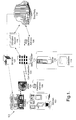
- Figure 1 is a block diagram illustrating some examples of elements that can be included in a system or method that uses a meter 104 with an electronic address 106 as a gateway (collectively the "system" 100).
- a building 102 is potentially any structure having a utility meter 104 with a fixed electronic address 106.
- Some buildings 102 are residential, such as detached single family homes, townhouses, condominiums, apartments, mobile homes, lofts, etc.
- Examples of non-residential buildings 102 include offices, warehouses, factories, stores, public areas, parks, remote water pumps, etc.
- the building 102 can house a variety of mobile and non-mobile devices (collectively "devices” 103) that can benefit from using the meter 104 as a gateway for communication between the building 102 and the outside world.
- devices can include general purpose computers such as tablet computers, laptop computers, desktop computers, and PDAs.
- Any "intelligent" appliance with an embedded computer capable of communicating with the meter 103 can be a device 104.
- the system 100 can flexibly accommodate future intelligent appliances, as well as a wide variety of different networking technologies and methodologies.
- more than one of the devices 103 will be connected to a network in the building 102. In other embodiments, there is no network of devices 103, but the devices 103 are capable of interacting with the meter 104.
- a meter 104 is a component connected to the building 102 that is operated and managed by a utility company. Examples of meters 104 can include electrical power meters, gas meters, and water meters. In the future, cable and satellite components may also server as meters 104. For a meter 104 to serve as a gateway for the flow of information in the system 100, the meter 104 should be addressable, (i.e. it should have an electronic address 106 such as an IP address).
- the meter 104 can be integrated into a nearby transformer to lower installation costs and improve the visual appeal of buildings 102.
- An electronic address 106 associated with the meter 104 allows the meter 104 to serve as an information gateway for the system 100. Potentially any unique identifier can serve as an electronic address 106, as long as it can be uniquely associated with the specific location where the meter is installed.
- a communication 108 is information exchanged between the meter 104 and a utility provider 110.
- the communication 108 can be transmitted over the same physical connection used by the utility provider 110 to provide the utility, such as an electrical power line used to provide electricity.
- the communication 108 can also be transmitted using satellites, earth relay stations, cellular telephone network, and network control centers. Any technology or combination of technologies that can be used to transmit information can be used by the system 100 to transfer information.
- a utility provider 110 is the company that provides the meter 104 to the building. In many embodiments of the system 100, the utility provider 110 operates the gateway functionality of the system 100. In other embodiments, an outside entity such as an application service provider (ASP) can be responsible for the aspects of the system 100 that do not directly relate to the providing of utility services to the building 102.
- ASP application service provider
- a server 112 is any device that is capable of storing information used to support the functionality of the system 100.
- One or more servers 112 will typically host one or more databases 114.
- the server 112 can be operated and managed by the utility provider 110, or those tasks can be performed by another entity such as an ASP.
- a database 114 is potentially any information technology methodology used to store information so that it can be accessed in the future.
- Databases 114 are typically relational databases, although object-oriented and hierarchical databases can also be used. Flat files, arrays, and other data structures can also be used to achieve the functionality of the database 114.
- Databases 114 are used by the system 100 to store information such as electronic addresses 106 associated with meters 104, as well as occupant and building information that is associated with the particular building 102 associated with the particular meter 104.
- Information relating to occupants of a building as well as to the building itself can be stored in one or more databases 114 as one or more occupant records 116.
- the variety of information that can be stored as occupant records 116 can vary as widely as the different ancillary services 120 (as identified above and below) that can be performed by the system 100.
- the occupant record 116 can include information relating to the structure, status, and functionality of those devices 103.
- Occupant information along with the corresponding electronic address 106 of the applicable meter 104 can be sent to a third party 118 for the purpose of providing services 120 that benefit either the building 102, the utility provider 104, and/or the third party 118.
- a third party 118 is any individual, organization, company, government entity, or non-profit organization 118 that is provided access to occupant information in order to perform the functionality of the system 100.
- the third party 118 could be the police department, the fire department, an ambulance, etc.
- An ancillary service 120 is any function, process, or advantage generated by the third party 118 that is influenced by the occupant information transmitted to the third party 118 by the system 100.
- Ancillary services 120 can also be referred to as services 120. Services 120 do not directly relate to providing of the utility to the building 102 by the utility provider 110.
- utility providers 110 are often best situated to possess up to date information relating to the occupants of a building 102. However, utility providers 110 typically have little motivation for storing and accessing up-to-date occupant records 116 using "addressable" meters 104 as gateways because utility providers 110 are not in the business of providing the ancillary services 120.
- the system 100 allows third parties 118 to benefit from the information library of the utility provider 110.
- third parties 118 typically provide the services 120 that are made possible by the system 100.
- the utility provider 110 could engage in the business and operations of what would otherwise be a third party 118.
- the system 100 anticipates that buildings 102, utility providers 110, and third parties 118 can each potentially benefit from the exchange of information made possible by the system 100.
- some embodiments of the system 100 may involve an application service provider ("ASP") 140 to maintain and operate the aspects of the system 100 that make information available to third parties 118.
- Utility providers 110 may not want to take on responsibilities that are not within the core competency of some utility providers 110.
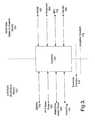
- FIG. 3 is a network diagram illustrating an example of a gateway 150 (e.g. the addressable 106 portion of the meter 104) between a LAN 152 and a WAN 154.
- a gateway 150 e.g. the addressable 106 portion of the meter 104
- LAN 152 e.g. the addressable 106 portion of the meter 104
- WAN 154 e.g. the Internet WAN 154
- a wide variety of different network connections can interact with the gateway 150.
- ZigBee 156 or some other form of wireless connectivity
- a KYZ meter pulse 158 or some other form of high quality shielded or unshielded signal wires
- a meter pulse 160 for water and/or gas flow information
- a home plug 162 or some other form of interactive network connectivity for various devices 103.
- PSTN public Switched Telephone Network
- Orbcomm Orbcomm line 164 or some other form of orbital network
- BPL Broadband over Powerline
- different services 120 can utilize a wide variety of different network connections. As indicated by the arrows at the bottom of the Figure, a downlink direction 170 is towards the building 102 and an uplink direction 172 points away from the building towards the outside world, i.e. where third parties 118 perform services 120 using the information made accessible by the system 100.
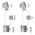
- Figure 4 is a block diagram illustrating an example of a subsystem-level view of the system 100.
- a provider subsystem 200 includes the infrastructural components controlled and operated by the utility provider 110, including the servers 112 and databases 114 used to store and access occupant records 116 that are associated with electronic addresses 106 which are in turn associated with meters 104 and buildings 102.
- the provider subsystem 200 also includes the mechanisms for communications 108 between the meter 104 and the utility provider 110.
- a service subsystem 202 includes the interactions of one or more third parties 118 as recipients of occupant information from the provider subsystem 200.
- the service subsystem 202 makes services 120 accessible to the system.
- An occupant subsystem 204 is the means by which occupants, their devices 103, and the buildings 102 inhabited by the occupants and devices 103 are made manifest to provider subsystem 200 or ancillary service subsystem 202. In addition to providing information to the system 100, the occupant subsystem 204 interacts with the services 120 made accessible by the services subsystem 202.
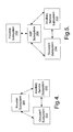
- Figure 5 is a block diagram illustrating an example of a subsystem-level view of the system 100 that includes an ASP subsystem 206.
- the ASP subsystem 206 serves as an intermediary between the provider subsystem 200 and the other subsystems.
- the embodiment illustrated in Figure 5 discloses an example of a utility provider 110 that wants to benefit from the system 100 and to make the functionality of the system 100 available to third parties 118 and to occupants without wanting to run the system 100 themselves.
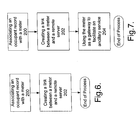
- Figure 6 is a flow chart diagram illustrating an example of a method for using a meter 104 as a gateway 150.
- an occupant record 116 is associated with the meter 104.
- a link is created between the meter 104 and a remote server 112 run by either the utility provider 110 or the ASP 140 acting on behalf of the utility provider 110.
- the information gateway 150 is ready for use, and the setup process ends.
- Figure 7 is a flow chart diagram illustrating an example of a method for using a meter 104 as a gateway 150 for ancillary services 120 provided by third parties 118.
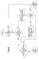
- Figure 8 is a flow chart diagram illustrating an example of a user authentication process.
- the authentication heuristic illustrated in Figure 8 is the sole method for determining whether or not an occupant is allowed to access a particular service 120 and the outcome of the heuristic is dispositive with respect to whether or not the occupant can access the service 120.
- occupant authentication can be performed as a "backup" to other forms of authentication, such as in the case of an online transaction. Failure to properly authenticate may merely result in a warning to the other party, or such failure may influence the transaction in other ways without necessarily prohibiting the transaction.
- the system 100 determines whether or not the residential supervisory and control gateway (RSCG) ID is available. If it is not, service is disallowed at 302.
- RSCG residential supervisory and control gateway
- the system 100 determines at 304 whether or not the access value for the service 120 is programmed into the device 103. If it is not, the service ID and the RSGC ID are sent to the third party 118 or the ASP 140 with an inquiry at 308 whether it is ok to program the device 104 for access. If at 308 it is not ok to provide for such access, service is disallowed at 302.
- the access information is programmed remotely by the ASP 140 or the third party 118 at 310. If the RSGC ID matches the programmed value at 312, service is allowed at 314. Otherwise, it is disallowed at 302.
- Services 120 are made accessible by the system 100 in a manner that is generally consistent with the process flow in Figure 1.
- a variety of services 120 by the system 100 could assist emergency response personnel in an emergency.
- Information relating to the occupants could be transmitted to the ambulance from the database 114 residing on the server 112.
- the lights at the building 102 could also be made to automatically flicker or flash, assisting the ambulance in finding the building 102.
- the occupants of the building 102 can be notified even when outside the building 102 if the temperature range within the building 102 exceeds certain ranges or if the heater and/or air conditioner ceases to function properly.
- a furnace or air conditioning failure can persist for hours without being detected if the occupants are not within the building 102 at the time of failure. By the time failure is detected, the building 102 can be extremely cold or warm, and the condition will only get worse before it is ultimately corrected. After the failure is corrected, the building 102 is returned to the desirable temperature, which often requires significant amounts of energy. By detecting failure early through remote means, power is saved and inconvenience minimized.
- the occupant of the building can be notified when the temperature exceeds the predefined range, which can be influenced by the time of day, day of the week, and season of the year. In some embodiments, the occupants can adjust the predefined temperature remotely over the Internet or some similar network.
- Monitoring can be performed remotely to determine whether a vacant property has become occupied. If an allegedly vacant building 102 is associated with a non-vacant electrical consumption profile, a message can be sent to the power company as well as to the owner of the building 102.
- Smart appliances and other devices 103 with data display and/or sound capability can communicate with the meter 104 using short range wireless or home plug communications.
- the electric meter 104 can relay the messages and replies to and/or from the sender.
- the provider 110 and/or ASP 140 can relay messages received from the Internet to occupants in the building 102.
- a diabetic may want to have blood sugar levels regularly transmitted to his or her doctor for the purpose of establishing a more natural insulin regimen.
- a heart patient may have regular blood pressure measurements sent to his or her cardiologist in order to look for patterns that can be used to help avoid any worsening of condition.
- the monitoring device 103 can be either hardwired to its sensors (such as a blood pressure cuff) or can utilize a wireless connection (such as a pulse rate watch). At predefined intervals, the monitoring device 103 can collect and store data from the sensors. The transmission time of the data can be influenced by whether or not a condition appears critical.
- An infrared detector can be used to indicate activity within a building for the purpose of elder care.
- the system 100 can provide a mechanism for care givers to have an indication that the person in question is going about their business normally. If something is wrong, the system 100 can transmit an early indication or warning about the particular symptom or condition.
- the system 100 can include a small module that can be plugged into a convenient outlet where the person being monitored would be expected to travel regularly.
- the module can include a low-cost PIR sensor that can detect the presence of the human body and a wired or wireless connection to the gateway 150. If the detector does not detect the presence of the person being monitored within a predetermined interval, such as 4 hours during the daytime and 9 hours at night, an alert could be sent to a caregiver or other appropriate agency. It is also possible to query the detector in order to determine that it is operating properly.
- the system 100 can be configured to detect the flushing of a toilet and reporting that information to a care provider or monitoring service.
- the system 100 can alert occupants when they are not at home that the sump pump is not working, and that the water level in a portion of the house is rising.
- a battery-operated water level detector device 103 can be installed with the sump.
- the device 103 can include a wireless connector to the gateway 150.
- a message can be sent to the home owner or a third party 118 monitoring service via the gateway 150.
- the water-level detector device 103 can be integrated into the sump pump itself and utilize the power of the line to communicate with the gateway 150.
- the sump pump includes a self diagnostic module that can detect failure or improper operation and communicate the status to the gateway 150 over power lines.
- Level detector devices 103 in communication with the gateway 150 can monitor food and water levels, notifying the occupants or temporary care givers in the case of unavailable occupants.
- Water sensor devices 103 in communication with the gateway 150 can monitor the environmental quality of drinking water.
- the monitor device 103 can look for levels of iron, hydrogen sulfide, e-coli bacteria, etc.
- Such sensors can be located at a well head for a group of buildings 102, and/or within individual buildings 102.
- a monitoring device 103 can be installed at a sewer lift station for a building 102. If a problem is detected, the gateway 150 can inform the occupant or the appropriate third party 118.
- the gateway 150 can be used as the primary network for security applications, or as a backup network in an instance where the primary network is not functional. Notification can be sent to third parties 118 such as the police as well as private security providers.
- the system 100 can confirm with third party 118 cable and satellite providers that the occupants in a building are authorized (e.g. they have paid for) the cable and/or satellite content being viewed.
- the system 100 can be configured to automatically prohibit fraudulent access, generate a warning, and/or report the fraud to the third party provider 118.
- the identity and location of occupants can be confirmed in online transactions by allowing the other party to request confirmation from the gateway 150.
- Access to cable and satellite content can be conditioned upon confirmation that access is warranted. Such confirmation can be provided through the gateway 150.
Landscapes
- Engineering & Computer Science (AREA)
- Computer Networks & Wireless Communication (AREA)
- Signal Processing (AREA)
- Automation & Control Theory (AREA)
- Telephonic Communication Services (AREA)
- Alarm Systems (AREA)
Applications Claiming Priority (2)
| Application Number | Priority Date | Filing Date | Title |
|---|---|---|---|
| US60431804P | 2004-08-25 | 2004-08-25 | |
| US11/183,602 US20060045105A1 (en) | 2004-08-25 | 2005-07-18 | System and method for using a utility meter |
Publications (1)
| Publication Number | Publication Date |
|---|---|
| EP1631009A1 true EP1631009A1 (de) | 2006-03-01 |
Family
ID=34979173
Family Applications (1)
| Application Number | Title | Priority Date | Filing Date |
|---|---|---|---|
| EP05076820A Withdrawn EP1631009A1 (de) | 2004-08-25 | 2005-08-05 | Vorrichtung und Verfahren zur Anwendung eines Verbrauchszählers |
Country Status (2)
| Country | Link |
|---|---|
| US (1) | US20060045105A1 (de) |
| EP (1) | EP1631009A1 (de) |
Cited By (2)
| Publication number | Priority date | Publication date | Assignee | Title |
|---|---|---|---|---|
| WO2007090225A1 (en) * | 2006-02-06 | 2007-08-16 | Uhs Systems Pty Ltd | Versatile utility gateway |
| WO2008097453A1 (en) * | 2007-02-02 | 2008-08-14 | Silver Spring Networks, Inc. | Method and system of providing ip-based packet communications with in-premise devices in a utility network |
Families Citing this family (59)
| Publication number | Priority date | Publication date | Assignee | Title |
|---|---|---|---|---|
| US7248158B2 (en) * | 2000-04-14 | 2007-07-24 | Current Technologies, Llc | Automated meter reading power line communication system and method |
| US6998962B2 (en) * | 2000-04-14 | 2006-02-14 | Current Technologies, Llc | Power line communication apparatus and method of using the same |
| EP1371219A4 (de) * | 2001-02-14 | 2006-06-21 | Current Tech Llc | Datenkommunikation über eine stromversorgungsleitung |
| US7224272B2 (en) * | 2002-12-10 | 2007-05-29 | Current Technologies, Llc | Power line repeater system and method |
| US7436321B2 (en) * | 2002-12-10 | 2008-10-14 | Current Technologies, Llc | Power line communication system with automated meter reading |
| US7321291B2 (en) * | 2004-10-26 | 2008-01-22 | Current Technologies, Llc | Power line communications system and method of operating the same |
| US7856032B2 (en) * | 2005-04-04 | 2010-12-21 | Current Technologies, Llc | Multi-function modem device |
| US7265664B2 (en) | 2005-04-04 | 2007-09-04 | Current Technologies, Llc | Power line communications system and method |
| US7627453B2 (en) | 2005-04-26 | 2009-12-01 | Current Communications Services, Llc | Power distribution network performance data presentation system and method |
| US7358808B2 (en) * | 2005-06-21 | 2008-04-15 | Current Technologies, Llc | Method and device for amplification of data signals over power lines |
| US7259657B2 (en) * | 2005-06-21 | 2007-08-21 | Current Technologies, Llc | Multi-subnet power line communications system and method |
| US7769149B2 (en) * | 2006-01-09 | 2010-08-03 | Current Communications Services, Llc | Automated utility data services system and method |
| US20080012724A1 (en) * | 2006-01-30 | 2008-01-17 | Corcoran Kevin F | Power line communications module and method |
| US7852207B2 (en) * | 2006-02-14 | 2010-12-14 | Current Technologies, Llc | Method for establishing power line communication link |
| US7764943B2 (en) * | 2006-03-27 | 2010-07-27 | Current Technologies, Llc | Overhead and underground power line communication system and method using a bypass |
| US7796025B2 (en) | 2006-03-27 | 2010-09-14 | Current Technologies, Llc | Power line communication device and method |
| US7467092B2 (en) * | 2006-04-14 | 2008-12-16 | Blu Trend, Llc | Systems and methods for the prevention of extended utility theft |
| US8073705B2 (en) * | 2006-04-14 | 2011-12-06 | Blu Trend, Llc | Systems and methods for the prevention of extended utility theft |
| WO2007146121A2 (en) * | 2006-06-08 | 2007-12-21 | Fairfax County Water Authority | Systems and methods for remote utility metering and meter monitoring |
| US8279080B2 (en) | 2006-06-08 | 2012-10-02 | Fairfax County Water Authority | Systems and methods for remote utility metering and meter monitoring |
| US9105181B2 (en) | 2006-06-08 | 2015-08-11 | Mueller International, Llc | Systems and methods for generating power through the flow of water |
| US20070297425A1 (en) * | 2006-06-23 | 2007-12-27 | George Chirco | Systems and methods for establishing a network over a substation dc/ac circuit |
| US20080103798A1 (en) * | 2006-10-25 | 2008-05-01 | Domenikos Steven D | Identity Protection |
| US8359278B2 (en) * | 2006-10-25 | 2013-01-22 | IndentityTruth, Inc. | Identity protection |
| US7859646B2 (en) * | 2007-01-24 | 2010-12-28 | Adelphi University | Interferometric method for improving the resolution of a lithographic system |
| US7908116B2 (en) | 2007-08-03 | 2011-03-15 | Ecofactor, Inc. | System and method for using a network of thermostats as tool to verify peak demand reduction |
| US7848900B2 (en) | 2008-09-16 | 2010-12-07 | Ecofactor, Inc. | System and method for calculating the thermal mass of a building |
| US8019567B2 (en) | 2007-09-17 | 2011-09-13 | Ecofactor, Inc. | System and method for evaluating changes in the efficiency of an HVAC system |
| US20090125351A1 (en) * | 2007-11-08 | 2009-05-14 | Davis Jr Robert G | System and Method for Establishing Communications with an Electronic Meter |
| US20090234803A1 (en) * | 2008-03-11 | 2009-09-17 | Continental Electrical Construction Company, Llc | Keyword search of business information system |
| US8010237B2 (en) | 2008-07-07 | 2011-08-30 | Ecofactor, Inc. | System and method for using ramped setpoint temperature variation with networked thermostats to improve efficiency |
| US8180492B2 (en) * | 2008-07-14 | 2012-05-15 | Ecofactor, Inc. | System and method for using a networked electronic device as an occupancy sensor for an energy management system |
| US20100262395A1 (en) * | 2009-04-08 | 2010-10-14 | Manu Sharma | System and Method for Determining a Phase Conductor Supplying Power to a Device |
| US20100262393A1 (en) * | 2009-04-08 | 2010-10-14 | Manu Sharma | System and Method for Determining a Phase Conductor Supplying Power to a Device |
| US8498753B2 (en) * | 2009-05-08 | 2013-07-30 | Ecofactor, Inc. | System, method and apparatus for just-in-time conditioning using a thermostat |
| US8740100B2 (en) | 2009-05-11 | 2014-06-03 | Ecofactor, Inc. | System, method and apparatus for dynamically variable compressor delay in thermostat to reduce energy consumption |
| US8596550B2 (en) | 2009-05-12 | 2013-12-03 | Ecofactor, Inc. | System, method and apparatus for identifying manual inputs to and adaptive programming of a thermostat |
| US20110202194A1 (en) * | 2010-02-15 | 2011-08-18 | General Electric Company | Sub-metering hardware for measuring energy data of an energy consuming device |
| US9652802B1 (en) | 2010-03-24 | 2017-05-16 | Consumerinfo.Com, Inc. | Indirect monitoring and reporting of a user's credit data |
| US8556188B2 (en) | 2010-05-26 | 2013-10-15 | Ecofactor, Inc. | System and method for using a mobile electronic device to optimize an energy management system |
| US10584890B2 (en) | 2010-05-26 | 2020-03-10 | Ecofactor, Inc. | System and method for using a mobile electronic device to optimize an energy management system |
| US8090477B1 (en) | 2010-08-20 | 2012-01-03 | Ecofactor, Inc. | System and method for optimizing use of plug-in air conditioners and portable heaters |
| EP3462317A1 (de) | 2011-02-18 | 2019-04-03 | CSidentity Corporation | System und verfahren zur identifikation kompromittierender persönlicher informationen im internet |
| US9631833B2 (en) * | 2011-06-17 | 2017-04-25 | Emerson Electric Co. | Climate control systems, and methods relating thereto |
| US8819793B2 (en) | 2011-09-20 | 2014-08-26 | Csidentity Corporation | Systems and methods for secure and efficient enrollment into a federation which utilizes a biometric repository |
| US11030562B1 (en) | 2011-10-31 | 2021-06-08 | Consumerinfo.Com, Inc. | Pre-data breach monitoring |
| US9870597B2 (en) * | 2011-11-18 | 2018-01-16 | Conservice, Llc | Systems and methods allowing multi-family property owners to consolidate retail electric provider charges with landlord provided utilities and services |
| US10048706B2 (en) | 2012-06-14 | 2018-08-14 | Ecofactor, Inc. | System and method for optimizing use of individual HVAC units in multi-unit chiller-based systems |
| US9157434B2 (en) * | 2013-01-22 | 2015-10-13 | PumpSpy Technology, LLC | Sump pump system with automated system monitoring and data collection |
| US8812387B1 (en) | 2013-03-14 | 2014-08-19 | Csidentity Corporation | System and method for identifying related credit inquiries |
| US9794355B2 (en) | 2014-04-08 | 2017-10-17 | Samsung Electronics Co., Ltd. | Systems and methods for adaptive notification networks |
| US9696360B2 (en) | 2014-06-04 | 2017-07-04 | Rf Group Llc | Sump/ejector pump monitor and sump/ejector pump failure warning system |
| US10339527B1 (en) | 2014-10-31 | 2019-07-02 | Experian Information Solutions, Inc. | System and architecture for electronic fraud detection |
| US11151468B1 (en) | 2015-07-02 | 2021-10-19 | Experian Information Solutions, Inc. | Behavior analysis using distributed representations of event data |
| US11187223B2 (en) | 2017-04-10 | 2021-11-30 | Logical Concepts, Inc. | Home flood prevention appliance system |
| US11022124B2 (en) * | 2017-04-10 | 2021-06-01 | Logical Concepts, Inc. | Whole home water appliance system |
| US10699028B1 (en) | 2017-09-28 | 2020-06-30 | Csidentity Corporation | Identity security architecture systems and methods |
| US10896472B1 (en) | 2017-11-14 | 2021-01-19 | Csidentity Corporation | Security and identity verification system and architecture |
| US12430646B2 (en) | 2021-04-12 | 2025-09-30 | Csidentity Corporation | Systems and methods of generating risk scores and predictive fraud modeling |
Citations (3)
| Publication number | Priority date | Publication date | Assignee | Title |
|---|---|---|---|---|
| US5699276A (en) * | 1995-12-15 | 1997-12-16 | Roos; Charles E. | Utility meter providing an interface between a digital network and home electronics |
| US20040059585A1 (en) * | 2002-09-24 | 2004-03-25 | Poweronedata Corporation | Utility power meter, metering system and method |
| US20040113810A1 (en) * | 2002-06-28 | 2004-06-17 | Mason Robert T. | Data collector for an automated meter reading system |
Family Cites Families (4)
| Publication number | Priority date | Publication date | Assignee | Title |
|---|---|---|---|---|
| US5010568A (en) * | 1989-04-04 | 1991-04-23 | Sparton Corporation | Remote meter reading method and apparatus |
| US6062166A (en) * | 1999-02-01 | 2000-05-16 | Macrina; John L. | Pet feeding system |
| JP3996428B2 (ja) * | 2001-12-25 | 2007-10-24 | 松下電器産業株式会社 | 異常検知装置及び異常検知システム |
| US7117051B2 (en) * | 2004-03-15 | 2006-10-03 | Tmio, Llc | Appliance communication system and method |
-
2005
- 2005-07-18 US US11/183,602 patent/US20060045105A1/en not_active Abandoned
- 2005-08-05 EP EP05076820A patent/EP1631009A1/de not_active Withdrawn
Patent Citations (3)
| Publication number | Priority date | Publication date | Assignee | Title |
|---|---|---|---|---|
| US5699276A (en) * | 1995-12-15 | 1997-12-16 | Roos; Charles E. | Utility meter providing an interface between a digital network and home electronics |
| US20040113810A1 (en) * | 2002-06-28 | 2004-06-17 | Mason Robert T. | Data collector for an automated meter reading system |
| US20040059585A1 (en) * | 2002-09-24 | 2004-03-25 | Poweronedata Corporation | Utility power meter, metering system and method |
Cited By (8)
| Publication number | Priority date | Publication date | Assignee | Title |
|---|---|---|---|---|
| WO2007090225A1 (en) * | 2006-02-06 | 2007-08-16 | Uhs Systems Pty Ltd | Versatile utility gateway |
| WO2008097453A1 (en) * | 2007-02-02 | 2008-08-14 | Silver Spring Networks, Inc. | Method and system of providing ip-based packet communications with in-premise devices in a utility network |
| US8364846B2 (en) | 2007-02-02 | 2013-01-29 | Silver Spring Networks, Inc. | Method and system of providing IP-based packet communications with in-premisis devices in a utility network |
| US8429295B2 (en) | 2007-02-02 | 2013-04-23 | Silver Spring Networks, Inc. | Method and system of providing IP-based packet communications in a utility network |
| US8489716B2 (en) | 2007-02-02 | 2013-07-16 | Silver Spring Networks, Inc. | Method and system of providing network addresses to in-premise devices in a utility network |
| US8892774B2 (en) | 2007-02-02 | 2014-11-18 | Silver Spring Networks, Inc. | Method and system of providing IP-based packet communications in a utility network |
| US9094458B2 (en) | 2007-02-02 | 2015-07-28 | Silver Spring Networks, Inc. | Method and system of providing network addresses to in-premise devices in a utility network |
| US9178716B2 (en) | 2007-02-02 | 2015-11-03 | Silver Spring Networks, Inc. | Method and system of providing IP-based packet communications in a utility network |
Also Published As
| Publication number | Publication date |
|---|---|
| US20060045105A1 (en) | 2006-03-02 |
Similar Documents
| Publication | Publication Date | Title |
|---|---|---|
| EP1631009A1 (de) | Vorrichtung und Verfahren zur Anwendung eines Verbrauchszählers | |
| US11363107B2 (en) | Location monitoring via a gateway | |
| US11526949B1 (en) | Determining risks related to activities on insured properties using informatic sensor data | |
| US10539713B2 (en) | Location monitoring via a gateway | |
| US10297138B2 (en) | Alternative billing modes for security and automation applications | |
| US20060244589A1 (en) | Method and system for an insurance auditor to audit a premise alarm system | |
| US10878220B2 (en) | Methods and systems for assigning locations to devices | |
| CN102024312B (zh) | 通过公用事业仪表读数基础设施进行报警报告 | |
| TWI237466B (en) | A method for supervising and supporting customer service rendered by service providers using a communication network, and the communication network system for realizing the same | |
| JP6183893B2 (ja) | 居住者安否確認システム | |
| KR101609999B1 (ko) | 검침장치를 이용한 독거 노인 모니터링 시스템 | |
| US20080243391A1 (en) | Information Managing/Providing System and Method | |
| JP2003006337A (ja) | 老人・要介護者遠隔支援システム | |
| JP5909832B1 (ja) | 安否監視機能を有する水道量集中検針装置 | |
| KR20070084019A (ko) | 중앙 게이트웨이 디바이스와 통신하는 복수의 센서디바이스를 포함하는 디바이스의 시스템 | |
| JP2017021496A (ja) | 高齢者向け集合住宅熱中症警報システム | |
| JP4466469B2 (ja) | 情報端末、地震情報の取得方法、およびそのプログラム | |
| KR102407150B1 (ko) | 지능형 응급상황 알람 서비스 시스템 및 방법 | |
| KR101329257B1 (ko) | 공동주택 거주자의 안전관리장치 및 안전관리방법 | |
| JP2002109667A (ja) | 生活見守り用管理装置 | |
| JP4386849B2 (ja) | 不在宅巡視システムと検針端末 | |
| JP7465461B2 (ja) | 見守りプログラム | |
| JP2002133573A (ja) | 水道使用量の検針値を利用した監視システム及び設備点検システムの操作方法 | |
| JP2019197590A (ja) | 通信システム | |
| JP2003281665A (ja) | 通信システムおよび通信端末 |
Legal Events
| Date | Code | Title | Description |
|---|---|---|---|
| PUAI | Public reference made under article 153(3) epc to a published international application that has entered the european phase |
Free format text: ORIGINAL CODE: 0009012 |
|
| AK | Designated contracting states |
Kind code of ref document: A1 Designated state(s): AT BE BG CH CY CZ DE DK EE ES FI FR GB GR HU IE IS IT LI LT LU LV MC NL PL PT RO SE SI SK TR |
|
| AX | Request for extension of the european patent |
Extension state: AL BA HR MK YU |
|
| 17P | Request for examination filed |
Effective date: 20060901 |
|
| 17Q | First examination report despatched |
Effective date: 20061009 |
|
| AKX | Designation fees paid |
Designated state(s): AT BE BG CH CY CZ DE DK EE ES FI FR GB GR HU IE IS IT LI LT LU LV MC NL PL PT RO SE SI SK TR |
|
| STAA | Information on the status of an ep patent application or granted ep patent |
Free format text: STATUS: THE APPLICATION IS DEEMED TO BE WITHDRAWN |
|
| 18D | Application deemed to be withdrawn |
Effective date: 20080923 |