EP1630673B1 - Vidage de mémoire avec un redémarrage rapide - Google Patents
Vidage de mémoire avec un redémarrage rapide Download PDFInfo
- Publication number
- EP1630673B1 EP1630673B1 EP05107626.3A EP05107626A EP1630673B1 EP 1630673 B1 EP1630673 B1 EP 1630673B1 EP 05107626 A EP05107626 A EP 05107626A EP 1630673 B1 EP1630673 B1 EP 1630673B1
- Authority
- EP
- European Patent Office
- Prior art keywords
- memory
- main memory
- physical main
- subset
- physical
- Prior art date
- Legal status (The legal status is an assumption and is not a legal conclusion. Google has not performed a legal analysis and makes no representation as to the accuracy of the status listed.)
- Not-in-force
Links
Images


Classifications
-
- G—PHYSICS
- G06—COMPUTING; CALCULATING OR COUNTING
- G06F—ELECTRIC DIGITAL DATA PROCESSING
- G06F11/00—Error detection; Error correction; Monitoring
- G06F11/07—Responding to the occurrence of a fault, e.g. fault tolerance
- G06F11/14—Error detection or correction of the data by redundancy in operation
- G06F11/1402—Saving, restoring, recovering or retrying
- G06F11/1415—Saving, restoring, recovering or retrying at system level
- G06F11/1441—Resetting or repowering
-
- G—PHYSICS
- G06—COMPUTING; CALCULATING OR COUNTING
- G06F—ELECTRIC DIGITAL DATA PROCESSING
- G06F9/00—Arrangements for program control, e.g. control units
- G06F9/06—Arrangements for program control, e.g. control units using stored programs, i.e. using an internal store of processing equipment to receive or retain programs
- G06F9/22—Microcontrol or microprogram arrangements
- G06F9/24—Loading of the microprogram
-
- G—PHYSICS
- G06—COMPUTING; CALCULATING OR COUNTING
- G06F—ELECTRIC DIGITAL DATA PROCESSING
- G06F11/00—Error detection; Error correction; Monitoring
- G06F11/07—Responding to the occurrence of a fault, e.g. fault tolerance
- G06F11/0703—Error or fault processing not based on redundancy, i.e. by taking additional measures to deal with the error or fault not making use of redundancy in operation, in hardware, or in data representation
- G06F11/0706—Error or fault processing not based on redundancy, i.e. by taking additional measures to deal with the error or fault not making use of redundancy in operation, in hardware, or in data representation the processing taking place on a specific hardware platform or in a specific software environment
- G06F11/073—Error or fault processing not based on redundancy, i.e. by taking additional measures to deal with the error or fault not making use of redundancy in operation, in hardware, or in data representation the processing taking place on a specific hardware platform or in a specific software environment in a memory management context, e.g. virtual memory or cache management
-
- G—PHYSICS
- G06—COMPUTING; CALCULATING OR COUNTING
- G06F—ELECTRIC DIGITAL DATA PROCESSING
- G06F11/00—Error detection; Error correction; Monitoring
- G06F11/07—Responding to the occurrence of a fault, e.g. fault tolerance
- G06F11/0703—Error or fault processing not based on redundancy, i.e. by taking additional measures to deal with the error or fault not making use of redundancy in operation, in hardware, or in data representation
- G06F11/0766—Error or fault reporting or storing
- G06F11/0778—Dumping, i.e. gathering error/state information after a fault for later diagnosis
-
- G—PHYSICS
- G06—COMPUTING; CALCULATING OR COUNTING
- G06F—ELECTRIC DIGITAL DATA PROCESSING
- G06F12/00—Accessing, addressing or allocating within memory systems or architectures
Definitions
- the present invention relates generally to computer systems, and more particularly to a method and system for writing a main memory data image to secondary storage while minimizing the delay in performing a required reboot.
- Operating systems typically are configured to perform memory dumps upon the occurrence of system crashes and serious failures involving hung user processes and services.
- a memory dump comprises copying the contents of main memory to secondary storage, for example in the form of a file stored on a hard disk or other secondary storage medium.
- a memory dump typically must be followed by a reboot of the system.
- Full memory dumps are indispensable resources for the analysis and correction of problems related to crashes and for the development of reliable systems.
- FIG. 1 of the drawings accompanying this specification provides a simplified illustration of the process by which a full memory dump is performed following a system crash, in accordance with the prior art. This illustration is instructive in clarifying the detailed description of the invention provided below.
- FIG. 1 events in time are represented, with time increasing from left to right. Initially, the system runs with its full amount of memory 101, here n gigabytes. A system crash event 103 occurs. A full memory dump of the n gigabytes of memory 101 is performed (signified by the arrow 105), following which the computer system undergoes a reboot 107.
- a memory dump of a portion of main memory such as the operating system kernel space or the space allocated to a specific process
- main memory such as the operating system kernel space or the space allocated to a specific process
- a "freeze" of the system it is not possible to generate a process-specific memory dump.
- US 2003/0145157 A1 discloses a computer system including a processor and a memory, wherein a fast memory dump is conducted upon receiving an indication that the processor requires reloading.
- the fast memory dump is conducted by initially dumping a portion of the memory, then reloading the processor, and then conducting a post-reload dump of the remainder of the memory after reloading the processor has commenced. As the post-reload dump continues, the remainder of the memory is gradually released for processor use. This permits the processor to return as a resource more quickly than would be the case if a full memory dump was conducted before reloading the processor.
- US20030140069 discloses a method to speed up the capture of critical data in a system having a primary or service partition and a plurality of secondary partitions.
- a secondary partition requests the critical data capture which is then executed by the service partition on its behalf.
- the service partition copies the data to a reserved memory space and afterwards restarts execution of the requesting partition.
- the present invention is directed towards providing a method and system for writing a data image in the main memory of a computer to a secondary storage device in such a way that the delay in performing a required reboot is minimized.
- a copy of a portion of the physical memory Prior to the reboot, a copy of a portion of the physical memory is made.
- the computer is rebooted, and the operating system is initially limited in its memory usage to the portion of memory that was copied prior to the reboot.
- the remaining physical memory is incrementally written to the storage device and dynamically added as memory for use by the operating system.
- a reserved memory space is maintained.
- the copying of the portion of the physical memory prior to reboot comprises copying the portion to the reserved space.
- the reserved memory space is written to the storage device.
- no reserved memory space is used; the copying of the portion of the physical memory prior to reboot comprises writing the portion to the secondary storage device.
- the physical memory copied prior to reboot includes one portion of memory that is copied to a reserved memory space, and another portion that is written to the secondary storage device.
- the invention is also directed towards a method for investigating a problem requiring a reboot, such as a system crash event. After the reboot, the memory image is scanned and a memory dump is incrementally generated. However, if during the scanning it is determined that the problem is a known issue or otherwise does not require completion of a full memory copy, the completion of the memory dump may be cancelled.
- FIGURE 1 is a diagram illustrating the generation of a full memory dump following a system crash and followed by a reboot, in accordance with the prior art.
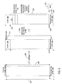
- FIG. 2 is a diagram illustrating the generation of a memory dump following a system crash, in which a reserved memory area is employed to permit a memory dump to be performed after reboot, in accordance with an embodiment of the invention.
- FIG. 3 is a diagram illustrating the generation of a memory dump following a system crash, in which a partial memory dump is performed prior to reboot and a reserved memory area is not used, in accordance with an embodiment .
- FIG. 4 is a diagram illustrating the generation of a memory dump following a system crash, in which features of the embodiments illustrated in FIGS. 2 and 3 are combined, in accordance with an embodiment .
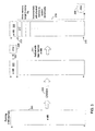
- FIG. 5 is a flow diagram illustrating steps of a process corresponding to the embodiment illustrated in FIG. 2 , in accordance with an embodiment of the invention.
- FIG. 6 is a flow diagram illustrating steps of a process corresponding to the embodiment illustrated in FIG. 3 , in accordance with an embodiment .
- FIG. 7 is a flowt diagram illustrating steps of a process corresponding to the embodiment illustrated in FIG. 4 , in accordance with an embodiment.
- FIG. 8 is a flow diagram illustrating steps of a method for investigating a problem requiring a reboot, in accordance with an embodiment of the invention.
- the present invention provides a technique that reduces the down time associated with the performance of a large memory copy to secondary storage in circumstances requiring a reboot.
- the completion of the memory dump is deferred until after the system reboot has occurred, thus enabling the system to reboot relatively quickly following an event such as a crash.
- An initial memory area is copied, thus freeing a limited memory space for use by the operating system following the reboot.
- the operating system After the reboot, the operating system initially operates with this limited amount of physical memory.
- the memory space existing outside of operating system control is scanned and written to a memory dump file or the like. After each discrete subrange of scanning and writing, the operating system adds a corresponding amount of physical memory to the system.
- FIGS. 2 , 3 , and 4 illustrate embodiments of the present invention.
- FIG. 1 these drawings depict events in time, with time increasing from left to right.
- FIG. 1 the description and depiction of sections of memory as being situated in particular regions of physical memory, such as at the beginning or end of the full range of physical memory, is purely for purposes of illustrative simplicity.
- a computer system is represented as being equipped with n megabytes of physical memory 201, but prior to a crash event it runs with (n-m) megabytes 203 of memory.
- An m-megabyte area of memory is "reserved" space 205.
- the size of the reserved area 205 can be configured to be up to half of the total onboard memory size.
- an initial m megabytes 209 of the memory 203 is copied (signified by the arrow 211) to the reserved area 205.
- This copying can be completed relatively quickly since it involves transferring data from and to main memory.
- a reboot 213 occurs, with the system configured to use m megabytes 209 of memory.
- the system employs a mechanism, such as, on certain architectures, setting up a private page directory entry (PDE) or the like, in order to access physical memory ranges that are not recognized by the operating system.
- PDE page directory entry
- a paging size of at least four megabytes is used.
- the memory image prior to the crash remains in the system memory. As noted below, in some embodiments this requires an alteration in the BIOS.
- the system writes the memory data in the reserved area 205 to a memory dump file 215; the writing is signified by the arrow 225.
- the system incrementally scans and writes the memory data in the range from m MB 217 to (n-m) MB 219 to the memory dump file 215.
- the scanning, writing and adding of memory is signified by the dashed arrow 223.
- a unit of memory 221 for example, every 256 MB or 512 MB in the range
- the operating system dynamically adds this now-available physical memory to the system.
- Certain embodiments implemented on architectures in which Physical Address Extensions (PAE) or similar memory-addressing mechanisms are available and supported by the operating system, use a virtual reserved space and map the virtual reserved space to the physical reserved space 205.
- Embodiments implemented on partitioned NUMA multiprocessor systems have a reserved area 205 for each node, in accordance with the physical memory layout of the system.
- the relevant topological information may be determined at boot time, such as by way of a Static Resource Affinity Table (SRAT) constructed by firmware.
- SRAT Static Resource Affinity Table
- no reserved memory area is used.
- the system is running with its full n megabytes of physical memory 301.
- an initial m megabytes 305 of the memory 301 is copied (signified by the arrow 307) to a memory dump file 309.
- a reboot 311 then occurs, with the system configured to use up to m megabytes 305 of memory.
- the pre-crash memory image remains in the system memory, apart from the data stored in the m megabytes 305 that were written 307 to the dump file 309 prior to the reboot 311.
- the system incrementally scans and writes the memory data in the range from m MB 313 to n MB 315 to the memory dump file 309.
- the operating system dynamically adds this now-available physical memory to the system.
- the scanning, writing and adding of memory is signified by the dashed arrow 319.
- FIG. 3 will require more time to complete the memory dump process than the previous embodiment described with reference to FIG. 2 .
- a partial memory space is written to disk after the crash occurs.
- this approach requires much less time than the prior art approach illustrated in FIG. 1 , in which the entire memory space is written to disk before reboot.
- the embodiment illustrated in FIG. 3 makes more economical usage of memory than the generally faster embodiment illustrated in FIG. 2 , since a reserved area is not used.
- FIG. 4 there is shown an illustration of a third embodiment that includes features of the embodiments illustrated in FIGS. 2 and 3 .
- the depicted system is equipped with n megabytes of memory 401, but initially it runs with (n-ml) megabytes 403 of memory, and it keeps an ml-megabyte reserved memory area 405. Following the occurrence of a crash event 407, an initial ml megabytes 409 of the memory 403 is copied (signified by the arrow 413) to the reserved area 405, and an additional m2 megabyte area 411 of the memory 403 is written to a memory dump file 417, signified by the arrow 415.
- a reboot 419 then occurs, with the system configured to use up to (m1+m2) megabytes 409, 411 of memory.
- the data in the reserved area 405 is written to the memory dump file 417; the writing is signified by the arrow 429.
- the system incrementally scans and writes the memory data in the range from (m1+m2) MB 421 to (n-m1) MB 423 to the memory dump file 417.
- the scanning, writing and adding of memory is signified by the dashed arrow 427.
- FIGS. 5 , 6 , and 7 illustrate the previously-described embodiments more explicitly as processes implemented by way of a computer.
- FIG. 5 illustrates the method associated with the embodiment illustrated in FIG. 2 .
- the computer boots with an m-megabyte reserved memory area.
- m megabytes of memory in this example, the first m megabytes of memory
- the computer reboots with up to m megabytes of memory.
- the data contained in the reserved area is written to a memory dump file.
- the operating system scans and writes the data image in the remaining physical memory to the dump file (not including the reserved area or the m-megabyte area that was copied to the reserved area).
- the system adds physical memory (for example, every 256 or 512 megabytes of scanned and written memory).
- FIG. 6 illustrates the method associated with the embodiment illustrated in FIG. 3 , in which a reserved area is not used.
- FIG. 7 illustrates the hybrid method associated with the embodiment illustrated in FIG. 4 .
- the computer is booted with an ml megabyte reserved area.
- a crash occurs (step 703)
- a first ml megabytes of memory are copied to the reserved area.
- an additional m2 megabytes of memory are written to a memory dump file.
- the computer reboots with up to (m1+m2) megabytes of memory.
- the ml megabytes of data contained in the reserved area are written to the dump file.
- the system scans and writes the data image in the remaining physical memory to the dump file (excluding the (m1+m2) megabyte area with which the system booted and the ml-megabyte reserved memory area). Incrementally, the system adds physical memory.
- embodiments of the invention provide a method for investigating a problem that requires a reboot, such as a system crash.
- a full diagnostic memory dump following the reboot may be avoided.
- a crash event occurs.
- m megabytes of memory are copied to a reserved memory space, to a memory dump file, or an ml-megabyte subset is copied to a reserved memory space and an m2-megabyte subset is written to a dump file.
- the system is rebooted with the operating system using up to m megabytes of memory.
- a reserved memory space is used, the reserved space is written to a dump file (step 807).
- a scan of the memory image begins. If, during the scanning, it is determined that the problem that necessitated the reboot is a known issue or easily-solvable issue (decision block 811), completion of a full memory dump may be cancelled (for example, by a system administrator) (step 815). Otherwise a full memory dump is incrementally generated as explained above (step 813).
- investigation of the problem need not wait until generation of a full memory dump but can begin immediately after the reboot. For those cases in which the problem is a known issue, the period of time after reboot during which the system runs with limited memory and slow performance is accordingly minimized.
- a new and useful invention is provided, permitting quicker reboots in situations in which a crash or similar event has occurred and it is desirable to perform a full memory dump of a system having a large physical memory size.
- the system runs relatively slowly because it is operating with reduced memory and because it is generating the memory dump.
- the invention provides system administrators with the ability to set a desired balance of down time and initial system performance after reboot, a choice that is not available in the prior art. For example, if the system is configured to use half of the onboard memory, then after a crash and reboot, the system operates with the expected memory size while immediately generating a memory dump. If a reserved area is used, the size of the reserved area can be set to accommodate the services required after reboot.
- Embodiments of the invention are implemented on computer systems in which Basic Input/Output System (BIOS) firmware or the like, typically embedded on onboard ROM or flash memory, is executed at boot time.
- BIOS Basic Input/Output System
- the BIOS includes as its first phase a Power-On Self-Test (POST) that tests and initializes the computer hardware prior to the loading of the operating system.
- POST generally includes a read/write test of system RAM.
- Embodiments of the invention therefore include embodiments in which the BIOS is configured in such a way that a memory test is not conducted during the reboot after a crash or other event in which a memory dump is desired, so that the contents of memory are preserved through the boot, thus permitting the postponement of the completion of the memory dump until after reboot.
- Other aspects of the invention may be achieved by way of changes to conventional BIOS definitions.
- the invention may be performed by way of, or may include or be situated within, general-purpose or special-purpose computing systems of various kinds, including but not limited to servers, workstations, or personal computers, and including both uniprocessor and multiprocessor machines.
- multiprocessor systems NUMA as well as UMA architectures are suitable, as indicated above.
- the general details of such computing systems and their varying configurations are rudimentary to those having skill in the art.
- the invention is particularly suitable for computer systems having a relatively large amount of main memory along with one or more secondary storage devices, either internal to the system or external (as for example external storage connected by way of a high-speed fiber channel).
- the invention has been described above as being practiced in settings in which a crash event occurs and a full memory dump is desired for diagnostic purposes. However, the invention is more broadly applicable to other situations in which it is desirable to write a large amount of memory to a secondary storage device and in which a reboot is necessary but delaying the reboot until completion of the memory write would be undesirable.
- a database may be mapped from hard disk to main memory in order to gain better performance for the database management system.
- the database memory image must be saved onto disk.
- the present invention provides a method and mechanism for enabling the data to be written to disk without an undesirable postponement of the reboot.
Claims (10)
- Procédé mis en oeuvre dans un système informatique comprenant une mémoire principale physique et un système d'exploitation, consistant à écrire des données contenues dans la mémoire principale physique sur un dispositif de stockage, le procédé comprenant :la copie (505) d'un premier sous-ensemble (209) de la mémoire principale physique (201) après un évènement de plantage (207) ;une commande du redémarrage (507) du système informatique, le redémarrage comprenant l'exécution d'un système élémentaire d'entrée/sortie BIOS, soit Basic Input/Output System, qui n'écrase pas les données contenues dans la mémoire principale physique, et la limitation, par le système d'exploitation fonctionnant sur le système informatique, de l'utilisation de la mémoire (507) suite au redémarrage au premier sous-ensemble de la mémoire principale physique ; etconcernant une ou plusieurs unités (221) de la mémoire principale physique autres que celles du premier sous-ensemble, pour chaque unité, l'écriture (511) de données de l'unité sur le dispositif de stockage et l'ajout dynamique de l'unité pour une utilisation par le système d'exploitation,dans lequel l'écriture de données sur le dispositif de stockage comprend l'écriture des données dans un fichier de vidage de mémoire ;caractérisé en ce que :le premier sous-ensemble de la mémoire principale physique est copié dans un espace- de mémoire réservé (205) de la mémoire principale physique, dans lequel le système informatique fonctionne avec la mémoire principale physique moins l'espace de mémoire réservé ;après le redémarrage du système informatique, l'écriture (509) de données de l'espace de mémoire réservé sur le dispositif de stockage ;le procédé étant mis en oeuvre par le système d'exploitation du système informatique.
- Procédé selon la revendication 1, dans lequel la copie du premier sous-ensemble de la mémoire principale physique dans l'espace de mémoire réservé comprend en outre la copie du premier sous-ensemble de la mémoire principale physique dans un espace de mémoire réservé dont la taille peut atteindre la moitié de la mémoire principale physique.
- Procédé selon la revendication 1, dans lequel la copie du premier sous-ensemble de la mémoire principale physique dans l'espace de mémoire réservé comprend en outre la copie du premier sous-ensemble de la mémoire principale physique dans un espace réservé virtuel qui est mappé vers un espace réservé physique.
- Procédé selon la revendication 1, dans lequel la copie du premier sous-ensemble de la mémoire principale physique dans l'espace de mémoire réservé comprend en outre la copie d'un premier sous-ensemble de la mémoire principale physique associé à une partition dans un système d'accès mémoire non uniforme NUMA, soit Non-Uniform Memory Access, dans un espace de mémoire réservé associé à la partition.
- Procédé selon la revendication 1, comprenant en outre, après le redémarrage du système informatique, l'établissement d'une entrée de répertoire de pages PDE, soit Page Directory Entry, privée pour accéder à un deuxième sous-ensemble de la mémoire principale physique qui n'est pas reconnu par le système d'exploitation.
- Procédé selon la revendication 1, comprenant en outre :par rapport auxdites une ou plusieurs unités de la mémoire, pour chaque unité :le balayage (809) de l'unité pour déterminer une cause du problème ; etsi le problème est connu, l'annulation de la mise en oeuvre d'un vidage de mémoire sur un dispositif de stockage, et autrement la génération du vidage de mémoire par rapport à l'unité.
- Procédé selon la revendication 6, dans lequel l'annulation de la mise en oeuvre du vidage de mémoire comprend en outre la mise à disposition de mémoire principale physique additionnelle pour une utilisation par le système d'exploitation.
- Système d'un système informatique pour écrire des données dans un dispositif de stockage, le système comprenant :une mémoire principale physique (201) contenant les données,un premier sous-ensemble (209) de la mémoire principale physique (201) ;un système BIOS qui ne commande pas l'écrasement des données contenues dans la mémoire principale physique ;un moyen pour copier le premier sous-ensemble (209) de la mémoire principale physique (201) après un évènement de plantage (207) ;un moyen pour commander un redémarrage, le redémarrage comprenant l'exécution d'un système BIOS qui n'écrase pas les données contenues dans la mémoire principale physique ;un moyen pour limiter l'utilisation de la mémoire au premier sous-ensemble de la mémoire principale physique, suite au redémarrage ; etun moyen pour, après le redémarrage et par rapport à une ou plusieurs unités (221) de la mémoire principale physique autres que celles du premier sous-ensemble, écrire pour chaque unité des données de l'unité sur le dispositif de stockage et ajouter dynamiquement l'unité pour une utilisation par le système d'exploitation, dans lequel l'écriture de données sur le dispositif de stockage comprend l'écriture des données dans un fichier de vidage de mémoire ;caractérisé en ce que :la mémoire principale physique comporte un espace de mémoire réservé (205) dans lequel le système informatique fonctionne avec la mémoire principale physique moins l'espace de mémoire réservé ;le moyen pour copier copie le premier sous-ensemble de la mémoire physique dans l'espace de mémoire réservé (205) de la mémoire principale physique ;le moyen pour écrire (509) écrit des données de l'espace de mémoire réservé sur le dispositif de stockage après le redémarrage ; etles moyens respectifs sont réalisés par un système d'exploitation configuré pour mettre en oeuvre les actions.
- Système selon la revendication 8, comprenant en outre une base de données en mémoire.
- Support lisible par un ordinateur et comportant des instructions exécutables par un ordinateur pour écrire des données contenues dans une mémoire principale physique sur un dispositif de stockage, les instructions
mettant en oeuvre le procédé selon l'une des revendications 1 à 7 lorsqu'elles sont exécutées.
Applications Claiming Priority (1)
| Application Number | Priority Date | Filing Date | Title |
|---|---|---|---|
| US10/924,712 US7509521B2 (en) | 2004-08-23 | 2004-08-23 | Memory dump generation with quick reboot |
Publications (3)
| Publication Number | Publication Date |
|---|---|
| EP1630673A2 EP1630673A2 (fr) | 2006-03-01 |
| EP1630673A3 EP1630673A3 (fr) | 2011-04-27 |
| EP1630673B1 true EP1630673B1 (fr) | 2014-12-03 |
Family
ID=35464214
Family Applications (1)
| Application Number | Title | Priority Date | Filing Date |
|---|---|---|---|
| EP05107626.3A Not-in-force EP1630673B1 (fr) | 2004-08-23 | 2005-08-19 | Vidage de mémoire avec un redémarrage rapide |
Country Status (5)
| Country | Link |
|---|---|
| US (1) | US7509521B2 (fr) |
| EP (1) | EP1630673B1 (fr) |
| JP (1) | JP5021190B2 (fr) |
| KR (1) | KR101201186B1 (fr) |
| CN (1) | CN100483347C (fr) |
Families Citing this family (30)
| Publication number | Priority date | Publication date | Assignee | Title |
|---|---|---|---|---|
| GB0405711D0 (en) * | 2004-03-13 | 2004-04-21 | Hewlett Packard Development Co | Method and apparatus for dumping memory |
| US7383471B2 (en) * | 2004-12-28 | 2008-06-03 | Hewlett-Packard Development Company, L.P. | Diagnostic memory dumping |
| JP2007087263A (ja) * | 2005-09-26 | 2007-04-05 | Nec Corp | ミラーメモリ構成のコンピュータシステムにおけるダンプ方法、ダンプ制御機構、およびダンププログラム |
| US7788537B1 (en) * | 2006-01-31 | 2010-08-31 | Emc Corporation | Techniques for collecting critical information from a memory dump |
| US7770056B2 (en) * | 2006-10-18 | 2010-08-03 | Hewlett-Packard Development Company, L.P. | System and method for dynamic page classification for memory dumping |
| US8127099B2 (en) * | 2006-12-26 | 2012-02-28 | International Business Machines Corporation | Resource recovery using borrowed blocks of memory |
| US7783932B1 (en) * | 2007-04-13 | 2010-08-24 | Network Appliance, Inc. | Method and apparatus for generating dynamic microcores |
| CN101295268B (zh) * | 2007-04-27 | 2011-03-02 | 国际商业机器公司 | 面向软件系统的分区存储器转储方法和装置 |
| JP5255348B2 (ja) * | 2007-07-16 | 2013-08-07 | ヒューレット−パッカード デベロップメント カンパニー エル.ピー. | クラッシュダンプ用のメモリアロケーション |
| US7818616B2 (en) * | 2007-07-25 | 2010-10-19 | Cisco Technology, Inc. | Warm reboot enabled kernel dumper |
| JP4838226B2 (ja) * | 2007-11-20 | 2011-12-14 | 富士通株式会社 | ネットワークロギング処理プログラム,情報処理システムおよびネットワークロギング情報自動退避方法 |
| US7818622B2 (en) * | 2008-04-29 | 2010-10-19 | International Business Machines Corporation | Method for recovering data processing system failures |
| JP5119047B2 (ja) * | 2008-05-29 | 2013-01-16 | 京セラドキュメントソリューションズ株式会社 | 操作表示装置及び画像形成装置 |
| JP5286942B2 (ja) * | 2008-05-30 | 2013-09-11 | 富士通株式会社 | 制御方法、制御プログラム及び情報処理装置 |
| US8578144B2 (en) * | 2010-08-04 | 2013-11-05 | International Business Machines Corporation | Partial hibernation restore for boot time reduction |
| CN102184145B (zh) | 2011-05-13 | 2013-04-17 | 杭州华三通信技术有限公司 | 重启数据不丢失方法及装置 |
| GB2508344A (en) | 2012-11-28 | 2014-06-04 | Ibm | Creating an operating system dump |
| KR102014083B1 (ko) * | 2012-12-31 | 2019-08-27 | 삼성전자주식회사 | 단말기의 메모리 관리방법 및 장치 |
| GB2520712A (en) | 2013-11-28 | 2015-06-03 | Ibm | Data dump method for a memory in a data processing system |
| JP2015114750A (ja) * | 2013-12-10 | 2015-06-22 | 富士通株式会社 | 調査用プログラム,情報処理装置及び情報処理方法 |
| WO2015116057A1 (fr) | 2014-01-29 | 2015-08-06 | Hewlett-Packard Development Company, L.P. | Vidage de ressources |
| JP6327026B2 (ja) | 2014-07-10 | 2018-05-23 | 富士通株式会社 | 情報処理装置、情報処理方法およびプログラム |
| US9442791B2 (en) | 2014-11-07 | 2016-09-13 | International Business Machines Corporation | Building an intelligent, scalable system dump facility |
| JP2016170463A (ja) * | 2015-03-11 | 2016-09-23 | 富士通株式会社 | 情報処理装置、カーネルダンプ方法、カーネルダンププログラム |
| US9710321B2 (en) * | 2015-06-23 | 2017-07-18 | Microsoft Technology Licensing, Llc | Atypical reboot data collection and analysis |
| US10025650B2 (en) | 2015-09-17 | 2018-07-17 | International Business Machines Corporation | Determining a trace of a system dump |
| US11385926B2 (en) * | 2017-02-17 | 2022-07-12 | Intel Corporation | Application and system fast launch by virtual address area container |
| US10585736B2 (en) | 2017-08-01 | 2020-03-10 | International Business Machines Corporation | Incremental dump with fast reboot |
| CN110309008B (zh) * | 2018-03-20 | 2023-06-20 | 浙江宇视科技有限公司 | 系统异常时内存数据的保存方法及系统 |
| US11644999B2 (en) * | 2021-09-10 | 2023-05-09 | Qualcomm Incorporated | Protecting memory regions based on occurrence of an event |
Citations (1)
| Publication number | Priority date | Publication date | Assignee | Title |
|---|---|---|---|---|
| US20030140069A1 (en) * | 2002-01-23 | 2003-07-24 | International Business Machines Corporation | System and method for using ancillary processors and storage to speed time critical data capture |
Family Cites Families (22)
| Publication number | Priority date | Publication date | Assignee | Title |
|---|---|---|---|---|
| JPH02199557A (ja) * | 1989-01-30 | 1990-08-07 | Hitachi Ltd | メモリダンプ取得方法 |
| JPH02292640A (ja) * | 1989-05-02 | 1990-12-04 | Nec Corp | メモリダンプ採取方式 |
| US5293612A (en) * | 1989-05-11 | 1994-03-08 | Tandem Computers Incorporated | Selective dump method and apparatus |
| JPH0512049A (ja) * | 1991-06-25 | 1993-01-22 | Nec Ibaraki Ltd | 障害情報採取方式 |
| JP3175684B2 (ja) * | 1998-03-25 | 2001-06-11 | 日本電気株式会社 | ダンプ出力制御方式 |
| US6226761B1 (en) * | 1998-09-24 | 2001-05-01 | International Business Machines Corporation | Post dump garbage collection |
| US6604123B1 (en) * | 1999-02-23 | 2003-08-05 | Lucent Technologies Inc. | Operating system transfer of control and parameter manipulation using portals |
| US6543010B1 (en) * | 1999-02-24 | 2003-04-01 | Hewlett-Packard Development Company, L.P. | Method and apparatus for accelerating a memory dump |
| JP2000267872A (ja) * | 1999-03-17 | 2000-09-29 | Fujitsu Ltd | 2重化システムにおける再開処理方式 |
| JP2001034508A (ja) * | 1999-07-22 | 2001-02-09 | Hitachi Ltd | メモリダンプ採取方法及びその実施装置並びにその処理プログラムを記録した記録媒体 |
| JP2001109648A (ja) * | 1999-10-04 | 2001-04-20 | Fujitsu Ltd | 情報取得方法、情報取得装置、及び記録媒体 |
| JP3903678B2 (ja) * | 2000-02-15 | 2007-04-11 | 株式会社日立製作所 | 計算機システムのダンプ処理方法 |
| JP2001290677A (ja) | 2000-04-07 | 2001-10-19 | Hitachi Ltd | 高速ダンプ採取方法 |
| JP2001290678A (ja) | 2000-04-07 | 2001-10-19 | Hitachi Ltd | 非同期メモリダンプ実行方式 |
| US6681348B1 (en) * | 2000-12-15 | 2004-01-20 | Microsoft Corporation | Creation of mini dump files from full dump files |
| US6671786B2 (en) * | 2001-06-07 | 2003-12-30 | Microsoft Corporation | System and method for mirroring memory with restricted access to main physical mirrored memory |
| US6658538B2 (en) * | 2001-06-21 | 2003-12-02 | International Business Machines Corporation | Non-uniform memory access (NUMA) data processing system having a page table including node-specific data storage and coherency control |
| US6687799B2 (en) * | 2002-01-31 | 2004-02-03 | Hewlett-Packard Development Company, L.P. | Expedited memory dumping and reloading of computer processors |
| US20030158842A1 (en) * | 2002-02-21 | 2003-08-21 | Eliezer Levy | Adaptive acceleration of retrieval queries |
| JP2003271694A (ja) * | 2002-03-18 | 2003-09-26 | Fujitsu Ltd | プロセッサを含む論理回路の検証用シミュレーション方法及び装置並びに論理回路検証用エラー検出プログラム |
| US7290175B1 (en) * | 2002-08-26 | 2007-10-30 | Unisys Corporation | Forcing a memory dump for computer system diagnosis |
| JP2004102395A (ja) | 2002-09-05 | 2004-04-02 | Hitachi Ltd | メモリダンプデータの取得方法および情報処理装置、ならびにそのプログラム |
-
2004
- 2004-08-23 US US10/924,712 patent/US7509521B2/en active Active
-
2005
- 2005-08-19 EP EP05107626.3A patent/EP1630673B1/fr not_active Not-in-force
- 2005-08-23 JP JP2005241646A patent/JP5021190B2/ja not_active Expired - Fee Related
- 2005-08-23 CN CNB2005100959387A patent/CN100483347C/zh not_active Expired - Fee Related
- 2005-08-23 KR KR1020050077136A patent/KR101201186B1/ko not_active IP Right Cessation
Patent Citations (1)
| Publication number | Priority date | Publication date | Assignee | Title |
|---|---|---|---|---|
| US20030140069A1 (en) * | 2002-01-23 | 2003-07-24 | International Business Machines Corporation | System and method for using ancillary processors and storage to speed time critical data capture |
Also Published As
| Publication number | Publication date |
|---|---|
| CN1760834A (zh) | 2006-04-19 |
| US7509521B2 (en) | 2009-03-24 |
| CN100483347C (zh) | 2009-04-29 |
| KR101201186B1 (ko) | 2012-11-13 |
| JP2006072997A (ja) | 2006-03-16 |
| US20060041739A1 (en) | 2006-02-23 |
| EP1630673A3 (fr) | 2011-04-27 |
| JP5021190B2 (ja) | 2012-09-05 |
| EP1630673A2 (fr) | 2006-03-01 |
| KR20060050560A (ko) | 2006-05-19 |
Similar Documents
| Publication | Publication Date | Title |
|---|---|---|
| EP1630673B1 (fr) | Vidage de mémoire avec un redémarrage rapide | |
| US7437524B2 (en) | Method and apparatus for dumping memory | |
| US7484127B2 (en) | Method and system for preserving crash dump in a diskless system | |
| KR100306456B1 (ko) | 오퍼레이팅시스템의재기동방법 | |
| US7433898B1 (en) | Methods and apparatus for shared storage journaling | |
| US7831857B2 (en) | Method and system for recovering from operating system crash or failure | |
| US8621144B2 (en) | Accelerated resume from hibernation in a cached disk system | |
| US20110213954A1 (en) | Method and apparatus for generating minimum boot image | |
| US20060242398A1 (en) | Booting from non-volatile memory | |
| US9298472B2 (en) | High-speed restart method, information processing device, and program | |
| US8032740B2 (en) | Update in-use flash memory without external interfaces | |
| US6802022B1 (en) | Maintenance of consistent, redundant mass storage images | |
| US20110107044A1 (en) | Memory migration | |
| KR20140023944A (ko) | 가상 디스크 스토리지 기술 | |
| JPH03278126A (ja) | 計算機システム立上げ方式 | |
| US6842823B1 (en) | Methods and apparatus for persistent volatile computer memory | |
| US20080195836A1 (en) | Method or Apparatus for Storing Data in a Computer System | |
| JP4322240B2 (ja) | 再起動方法、システム及びプログラム | |
| US20110138118A1 (en) | Memory disc composition method and apparatus using main memory | |
| CN113127263B (zh) | 一种内核崩溃恢复方法、装置、设备及存储介质 | |
| US10346234B2 (en) | Information processing system including physical memory, flag storage unit, recording device and saving device, information processing apparatus, information processing method, and computer-readable non-transitory storage medium | |
| WO2006019656A2 (fr) | Systeme et procede de gestion de memoire | |
| CN111858116A (zh) | 一种信息记录方法、装置、设备及可读存储介质 | |
| JP2006172100A (ja) | オペレーティングシステムの高速切替え方式及びその方法 | |
| US7210033B1 (en) | Method, system, and computer-readable medium for enabling multi-segmented recovery of basic input output system program code in a computer system |
Legal Events
| Date | Code | Title | Description |
|---|---|---|---|
| PUAI | Public reference made under article 153(3) epc to a published international application that has entered the european phase |
Free format text: ORIGINAL CODE: 0009012 |
|
| AK | Designated contracting states |
Kind code of ref document: A2 Designated state(s): AT BE BG CH CY CZ DE DK EE ES FI FR GB GR HU IE IS IT LI LT LU LV MC NL PL PT RO SE SI SK TR |
|
| AX | Request for extension of the european patent |
Extension state: AL BA HR MK YU |
|
| PUAL | Search report despatched |
Free format text: ORIGINAL CODE: 0009013 |
|
| AK | Designated contracting states |
Kind code of ref document: A3 Designated state(s): AT BE BG CH CY CZ DE DK EE ES FI FR GB GR HU IE IS IT LI LT LU LV MC NL PL PT RO SE SI SK TR |
|
| AX | Request for extension of the european patent |
Extension state: AL BA HR MK YU |
|
| 17P | Request for examination filed |
Effective date: 20111021 |
|
| AKX | Designation fees paid |
Designated state(s): AT BE BG CH CY CZ DE DK EE ES FI FR GB GR HU IE IS IT LI LT LU LV MC NL PL PT RO SE SI SK TR |
|
| 17Q | First examination report despatched |
Effective date: 20120309 |
|
| RIC1 | Information provided on ipc code assigned before grant |
Ipc: G06F 11/07 20060101ALI20131120BHEP Ipc: G06F 11/14 20060101AFI20131120BHEP |
|
| GRAP | Despatch of communication of intention to grant a patent |
Free format text: ORIGINAL CODE: EPIDOSNIGR1 |
|
| INTG | Intention to grant announced |
Effective date: 20140110 |
|
| GRAP | Despatch of communication of intention to grant a patent |
Free format text: ORIGINAL CODE: EPIDOSNIGR1 |
|
| INTG | Intention to grant announced |
Effective date: 20140613 |
|
| GRAS | Grant fee paid |
Free format text: ORIGINAL CODE: EPIDOSNIGR3 |
|
| GRAA | (expected) grant |
Free format text: ORIGINAL CODE: 0009210 |
|
| AK | Designated contracting states |
Kind code of ref document: B1 Designated state(s): AT BE BG CH CY CZ DE DK EE ES FI FR GB GR HU IE IS IT LI LT LU LV MC NL PL PT RO SE SI SK TR |
|
| REG | Reference to a national code |
Ref country code: GB Ref legal event code: FG4D |
|
| REG | Reference to a national code |
Ref country code: CH Ref legal event code: EP Ref country code: AT Ref legal event code: REF Ref document number: 699723 Country of ref document: AT Kind code of ref document: T Effective date: 20141215 |
|
| REG | Reference to a national code |
Ref country code: IE Ref legal event code: FG4D |
|
| REG | Reference to a national code |
Ref country code: DE Ref legal event code: R096 Ref document number: 602005045332 Country of ref document: DE Effective date: 20150115 |
|
| REG | Reference to a national code |
Ref country code: CH Ref legal event code: PUE Owner name: MICROSOFT TECHNOLOGY LICENSING, LLC, US Free format text: FORMER OWNER: MICROSOFT CORPORATION, US |
|
| REG | Reference to a national code |
Ref country code: NL Ref legal event code: VDEP Effective date: 20141203 |
|
| REG | Reference to a national code |
Ref country code: AT Ref legal event code: MK05 Ref document number: 699723 Country of ref document: AT Kind code of ref document: T Effective date: 20141203 Ref country code: GB Ref legal event code: 732E Free format text: REGISTERED BETWEEN 20150319 AND 20150325 |
|
| RAP2 | Party data changed (patent owner data changed or rights of a patent transferred) |
Owner name: MICROSOFT TECHNOLOGY LICENSING, LLC |
|
| PG25 | Lapsed in a contracting state [announced via postgrant information from national office to epo] |
Ref country code: NL Free format text: LAPSE BECAUSE OF FAILURE TO SUBMIT A TRANSLATION OF THE DESCRIPTION OR TO PAY THE FEE WITHIN THE PRESCRIBED TIME-LIMIT Effective date: 20141203 Ref country code: ES Free format text: LAPSE BECAUSE OF FAILURE TO SUBMIT A TRANSLATION OF THE DESCRIPTION OR TO PAY THE FEE WITHIN THE PRESCRIBED TIME-LIMIT Effective date: 20141203 Ref country code: LT Free format text: LAPSE BECAUSE OF FAILURE TO SUBMIT A TRANSLATION OF THE DESCRIPTION OR TO PAY THE FEE WITHIN THE PRESCRIBED TIME-LIMIT Effective date: 20141203 Ref country code: FI Free format text: LAPSE BECAUSE OF FAILURE TO SUBMIT A TRANSLATION OF THE DESCRIPTION OR TO PAY THE FEE WITHIN THE PRESCRIBED TIME-LIMIT Effective date: 20141203 |
|
| REG | Reference to a national code |
Ref country code: LT Ref legal event code: MG4D |
|
| PG25 | Lapsed in a contracting state [announced via postgrant information from national office to epo] |
Ref country code: CY Free format text: LAPSE BECAUSE OF FAILURE TO SUBMIT A TRANSLATION OF THE DESCRIPTION OR TO PAY THE FEE WITHIN THE PRESCRIBED TIME-LIMIT Effective date: 20141203 Ref country code: GR Free format text: LAPSE BECAUSE OF FAILURE TO SUBMIT A TRANSLATION OF THE DESCRIPTION OR TO PAY THE FEE WITHIN THE PRESCRIBED TIME-LIMIT Effective date: 20150304 Ref country code: LV Free format text: LAPSE BECAUSE OF FAILURE TO SUBMIT A TRANSLATION OF THE DESCRIPTION OR TO PAY THE FEE WITHIN THE PRESCRIBED TIME-LIMIT Effective date: 20141203 Ref country code: SE Free format text: LAPSE BECAUSE OF FAILURE TO SUBMIT A TRANSLATION OF THE DESCRIPTION OR TO PAY THE FEE WITHIN THE PRESCRIBED TIME-LIMIT Effective date: 20141203 Ref country code: AT Free format text: LAPSE BECAUSE OF FAILURE TO SUBMIT A TRANSLATION OF THE DESCRIPTION OR TO PAY THE FEE WITHIN THE PRESCRIBED TIME-LIMIT Effective date: 20141203 |
|
| REG | Reference to a national code |
Ref country code: FR Ref legal event code: TP Owner name: MICROSOFT TECHNOLOGY LICENSING, LLC, US Effective date: 20150429 |
|
| PG25 | Lapsed in a contracting state [announced via postgrant information from national office to epo] |
Ref country code: PT Free format text: LAPSE BECAUSE OF FAILURE TO SUBMIT A TRANSLATION OF THE DESCRIPTION OR TO PAY THE FEE WITHIN THE PRESCRIBED TIME-LIMIT Effective date: 20150403 Ref country code: EE Free format text: LAPSE BECAUSE OF FAILURE TO SUBMIT A TRANSLATION OF THE DESCRIPTION OR TO PAY THE FEE WITHIN THE PRESCRIBED TIME-LIMIT Effective date: 20141203 Ref country code: SK Free format text: LAPSE BECAUSE OF FAILURE TO SUBMIT A TRANSLATION OF THE DESCRIPTION OR TO PAY THE FEE WITHIN THE PRESCRIBED TIME-LIMIT Effective date: 20141203 Ref country code: RO Free format text: LAPSE BECAUSE OF FAILURE TO SUBMIT A TRANSLATION OF THE DESCRIPTION OR TO PAY THE FEE WITHIN THE PRESCRIBED TIME-LIMIT Effective date: 20141203 Ref country code: CZ Free format text: LAPSE BECAUSE OF FAILURE TO SUBMIT A TRANSLATION OF THE DESCRIPTION OR TO PAY THE FEE WITHIN THE PRESCRIBED TIME-LIMIT Effective date: 20141203 |
|
| PG25 | Lapsed in a contracting state [announced via postgrant information from national office to epo] |
Ref country code: IS Free format text: LAPSE BECAUSE OF FAILURE TO SUBMIT A TRANSLATION OF THE DESCRIPTION OR TO PAY THE FEE WITHIN THE PRESCRIBED TIME-LIMIT Effective date: 20150403 Ref country code: PL Free format text: LAPSE BECAUSE OF FAILURE TO SUBMIT A TRANSLATION OF THE DESCRIPTION OR TO PAY THE FEE WITHIN THE PRESCRIBED TIME-LIMIT Effective date: 20141203 |
|
| REG | Reference to a national code |
Ref country code: DE Ref legal event code: R097 Ref document number: 602005045332 Country of ref document: DE |
|
| PLBE | No opposition filed within time limit |
Free format text: ORIGINAL CODE: 0009261 |
|
| STAA | Information on the status of an ep patent application or granted ep patent |
Free format text: STATUS: NO OPPOSITION FILED WITHIN TIME LIMIT |
|
| PG25 | Lapsed in a contracting state [announced via postgrant information from national office to epo] |
Ref country code: DK Free format text: LAPSE BECAUSE OF FAILURE TO SUBMIT A TRANSLATION OF THE DESCRIPTION OR TO PAY THE FEE WITHIN THE PRESCRIBED TIME-LIMIT Effective date: 20141203 |
|
| 26N | No opposition filed |
Effective date: 20150904 |
|
| PG25 | Lapsed in a contracting state [announced via postgrant information from national office to epo] |
Ref country code: IT Free format text: LAPSE BECAUSE OF FAILURE TO SUBMIT A TRANSLATION OF THE DESCRIPTION OR TO PAY THE FEE WITHIN THE PRESCRIBED TIME-LIMIT Effective date: 20141203 |
|
| PG25 | Lapsed in a contracting state [announced via postgrant information from national office to epo] |
Ref country code: SI Free format text: LAPSE BECAUSE OF FAILURE TO SUBMIT A TRANSLATION OF THE DESCRIPTION OR TO PAY THE FEE WITHIN THE PRESCRIBED TIME-LIMIT Effective date: 20141203 |
|
| PG25 | Lapsed in a contracting state [announced via postgrant information from national office to epo] |
Ref country code: MC Free format text: LAPSE BECAUSE OF FAILURE TO SUBMIT A TRANSLATION OF THE DESCRIPTION OR TO PAY THE FEE WITHIN THE PRESCRIBED TIME-LIMIT Effective date: 20141203 Ref country code: LU Free format text: LAPSE BECAUSE OF FAILURE TO SUBMIT A TRANSLATION OF THE DESCRIPTION OR TO PAY THE FEE WITHIN THE PRESCRIBED TIME-LIMIT Effective date: 20150819 |
|
| REG | Reference to a national code |
Ref country code: CH Ref legal event code: PL |
|
| PG25 | Lapsed in a contracting state [announced via postgrant information from national office to epo] |
Ref country code: LI Free format text: LAPSE BECAUSE OF NON-PAYMENT OF DUE FEES Effective date: 20150831 Ref country code: CH Free format text: LAPSE BECAUSE OF NON-PAYMENT OF DUE FEES Effective date: 20150831 |
|
| PG25 | Lapsed in a contracting state [announced via postgrant information from national office to epo] |
Ref country code: BE Free format text: LAPSE BECAUSE OF FAILURE TO SUBMIT A TRANSLATION OF THE DESCRIPTION OR TO PAY THE FEE WITHIN THE PRESCRIBED TIME-LIMIT Effective date: 20141203 |
|
| REG | Reference to a national code |
Ref country code: IE Ref legal event code: MM4A |
|
| REG | Reference to a national code |
Ref country code: FR Ref legal event code: PLFP Year of fee payment: 12 |
|
| PG25 | Lapsed in a contracting state [announced via postgrant information from national office to epo] |
Ref country code: IE Free format text: LAPSE BECAUSE OF NON-PAYMENT OF DUE FEES Effective date: 20150819 |
|
| PG25 | Lapsed in a contracting state [announced via postgrant information from national office to epo] |
Ref country code: BG Free format text: LAPSE BECAUSE OF FAILURE TO SUBMIT A TRANSLATION OF THE DESCRIPTION OR TO PAY THE FEE WITHIN THE PRESCRIBED TIME-LIMIT Effective date: 20141203 Ref country code: HU Free format text: LAPSE BECAUSE OF FAILURE TO SUBMIT A TRANSLATION OF THE DESCRIPTION OR TO PAY THE FEE WITHIN THE PRESCRIBED TIME-LIMIT; INVALID AB INITIO Effective date: 20050819 |
|
| REG | Reference to a national code |
Ref country code: FR Ref legal event code: PLFP Year of fee payment: 13 |
|
| PG25 | Lapsed in a contracting state [announced via postgrant information from national office to epo] |
Ref country code: TR Free format text: LAPSE BECAUSE OF FAILURE TO SUBMIT A TRANSLATION OF THE DESCRIPTION OR TO PAY THE FEE WITHIN THE PRESCRIBED TIME-LIMIT Effective date: 20141203 |
|
| REG | Reference to a national code |
Ref country code: DE Ref legal event code: R082 Ref document number: 602005045332 Country of ref document: DE Representative=s name: GRUENECKER PATENT- UND RECHTSANWAELTE PARTG MB, DE Ref country code: DE Ref legal event code: R081 Ref document number: 602005045332 Country of ref document: DE Owner name: MICROSOFT TECHNOLOGY LICENSING, LLC, REDMOND, US Free format text: FORMER OWNER: MICROSOFT CORP., REDMOND, WASH., US |
|
| REG | Reference to a national code |
Ref country code: FR Ref legal event code: PLFP Year of fee payment: 14 |
|
| PGFP | Annual fee paid to national office [announced via postgrant information from national office to epo] |
Ref country code: FR Payment date: 20190711 Year of fee payment: 15 Ref country code: DE Payment date: 20190806 Year of fee payment: 15 |
|
| PGFP | Annual fee paid to national office [announced via postgrant information from national office to epo] |
Ref country code: GB Payment date: 20190815 Year of fee payment: 15 |
|
| REG | Reference to a national code |
Ref country code: DE Ref legal event code: R119 Ref document number: 602005045332 Country of ref document: DE |
|
| GBPC | Gb: european patent ceased through non-payment of renewal fee |
Effective date: 20200819 |
|
| PG25 | Lapsed in a contracting state [announced via postgrant information from national office to epo] |
Ref country code: DE Free format text: LAPSE BECAUSE OF NON-PAYMENT OF DUE FEES Effective date: 20210302 Ref country code: FR Free format text: LAPSE BECAUSE OF NON-PAYMENT OF DUE FEES Effective date: 20200831 |
|
| PG25 | Lapsed in a contracting state [announced via postgrant information from national office to epo] |
Ref country code: GB Free format text: LAPSE BECAUSE OF NON-PAYMENT OF DUE FEES Effective date: 20200819 |