EP1630448A1 - Shock absorbing element for a vehicle and corresponding chassis - Google Patents
Shock absorbing element for a vehicle and corresponding chassis Download PDFInfo
- Publication number
- EP1630448A1 EP1630448A1 EP05291763A EP05291763A EP1630448A1 EP 1630448 A1 EP1630448 A1 EP 1630448A1 EP 05291763 A EP05291763 A EP 05291763A EP 05291763 A EP05291763 A EP 05291763A EP 1630448 A1 EP1630448 A1 EP 1630448A1
- Authority
- EP
- European Patent Office
- Prior art keywords
- bar
- element according
- section
- openings
- vehicle
- Prior art date
- Legal status (The legal status is an assumption and is not a legal conclusion. Google has not performed a legal analysis and makes no representation as to the accuracy of the status listed.)
- Granted
Links
Images
Classifications
-
- F—MECHANICAL ENGINEERING; LIGHTING; HEATING; WEAPONS; BLASTING
- F16—ENGINEERING ELEMENTS AND UNITS; GENERAL MEASURES FOR PRODUCING AND MAINTAINING EFFECTIVE FUNCTIONING OF MACHINES OR INSTALLATIONS; THERMAL INSULATION IN GENERAL
- F16F—SPRINGS; SHOCK-ABSORBERS; MEANS FOR DAMPING VIBRATION
- F16F7/00—Vibration-dampers; Shock-absorbers
- F16F7/12—Vibration-dampers; Shock-absorbers using plastic deformation of members
- F16F7/125—Units with a telescopic-like action as one member moves into, or out of a second member
Definitions
- the present invention relates to a shock absorbing element for a vehicle, of the type comprising a first bar.
- Structural elements mounted on motor vehicle frames are known. Such elements are for example extension elements mounted between frame rails and a bumper bar. These elements must exhibit defined deformation behavior during an impact, as well as a high energy absorption capacity for a given deformation.
- the object of the present invention is to provide a structural element which has such properties.
- the invention relates to an element of the aforementioned type, characterized in that it comprises a second bar overlapping the first bar in an overlapping zone, and in that the two bars are fixed one to the other. other exclusively at an attachment location in the overlap area.
- the invention further relates to a vehicle chassis, comprising two parts connected by at least one structural element, characterized in that the element is a shock absorbing element as defined above.
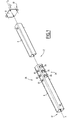
- Figure 1 a shock absorbing element of a motor vehicle, designated by the general reference 2.
- the element 2 comprises an inner bar 4, an outer bar 6 and a connecting flange 8.
- the inner bar 4 has a proximal end 10 of the element, on which the connecting flange 8 is fixed. mounted state, a bumper bar not shown is fixed to the flange 8.
- the outer bar 6 has a distal end 12 fixed for example to a not shown spar of a chassis of a vehicle.
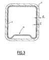
- the two bars 4, 6 are extruded profiles of axis XX, whose cross section is hollow and identical over the entire axial length respectively. As is apparent from Figure 3, the cross sections are substantially quadrilateral in shape, in this case square.
- the outer contour of the inner bar 4 is substantially conjugate with the inner contour of the outer bar 6.
- a central portion 14 of one face of the cross section of the inner bar 4 is set back from the surface of the outer bar 6
- the material thickness e1 of the inner bar 4 is smaller than the material thickness e2 of the outer bar 6.
- the two bars 4, 6 are made of metal, preferably steel.
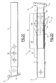
- the two bars 4, 6 are nested one inside the other over part of their axial length forming an overlap zone 18 (see Figure 2D).
- the two bars 4, 6 are attached locally to each other by a weld seam 20 located at the proximal end of the outer bar 6 and in the running portion of the inner bar 4.
- the overlap zone 18 located the distal side of the weld bead 20 is devoid of means for fixing the two bars to one another.
- at least the portion of the outer bar 6 adjacent to the overlap zone 18 comprises a free section identical to the cross section of the inner bar 4. It forms a displacement zone 22 of the inner bar 4 with respect to the outer bar 6.
- the two bars 4, 6 are axially slidably movable relative to each other.
- the bar 4, at least in the overlap zone 18, is devoid of weakening zones, such as openings.
- the outer bar 6 comprises a guiding section 23A adjacent to the displacement zone 22 and a weakened section 23B situated between the guiding section 23A and the weld bead 20.
- the weakened section 23B has a lower rigidity to the guide portion 23A.
- the axial compression force of the section 23B is smaller than that of the section 23A.
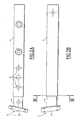
- the weakened section 23B comprises a main row 24 of weakening openings 26 and two secondary rows 28 of weakening openings 30. These rows 24, 28 extend axially exclusively inside the overlap area 18.
- Each row 24, 28 is disposed on one face of the bar 6, the secondary rows 28 being disposed on the two faces adjacent to the face of the main row 24, vis-à-vis one another.
- the fourth side of the bar is full and devoid of openings, so that during a shock, the inner bar 4 is deflected in an opposite direction of this face.
- the bar therefore has a predefined direction of deformation.
- all the openings 26, 30 are circular through openings, but they may have other shapes.
- the openings 26 and 30 may have an oval, square or rectangular shape.
- the main row 24 has openings 26 whose size increases progressively from the proximal side to the distal side.
- the openings 30 of the secondary rows 28 have identical sizes, in this case identical diameters, and the openings 30 of the two rows 28 are axially aligned.
- the openings 30 are axially offset openings 26, in this case an axial half-distance of two adjacent openings 26.
- the behavior of the structural element 2 according to the invention during an impact is as follows.
- the deformation of the element 2 is substantially axial and not directed laterally which leads to a high energy absorption capacity. Moreover, thanks to the presence of the openings 26, 30, it is the part having openings which is deformed, and not another part of the structural element.
- the inner bar 4 comprises the weakened section 23B and the guide portion 23A, while the outer bar 6 is rigid over its entire length.
- the weld 20 is located at the distal end of the inner bar 4 and the weakened section 23B is located between the weld 20 and the guide portion 23A.
- the element 2 Due to the fact that the thickness e1 of the bar 4 is less than the thickness e2 of the bar 6, after complete deformation of the weakened section 23B, it is the portion of the bar 4 extending outside the bar 6 which is distorted. Thus, the element 2 has a predetermined deformation behavior.
Landscapes
- Engineering & Computer Science (AREA)
- General Engineering & Computer Science (AREA)
- Mechanical Engineering (AREA)
- Vibration Dampers (AREA)
- Body Structure For Vehicles (AREA)
Abstract
Description
La présente invention concerne un élément d'amortissement de choc pour véhicule, du type comportant une première barre.The present invention relates to a shock absorbing element for a vehicle, of the type comprising a first bar.
On connaît des éléments de structure montés sur des châssis de véhicules automobiles. De tels éléments sont par exemple des éléments de rallonge montés entre des longerons de châssis et une barre de pare-chocs. Ces éléments doivent présenter un comportement de déformation défini lors d'un choc, ainsi qu'une haute capacité d'absorption d'énergie pour une déformation donnée.Structural elements mounted on motor vehicle frames are known. Such elements are for example extension elements mounted between frame rails and a bumper bar. These elements must exhibit defined deformation behavior during an impact, as well as a high energy absorption capacity for a given deformation.
La présente invention a pour but de fournir un élément de structure qui présente de tels propriétés.The object of the present invention is to provide a structural element which has such properties.
A cet effet l'invention a pour objet un élément du type précité, caractérisé en ce qu'il comprend une seconde barre chevauchant la première barre dans une zone de chevauchement, et en ce que les deux barres sont fixées l'une à l'autre exclusivement à un emplacement de fixation situé dans la zone de chevauchement.For this purpose the invention relates to an element of the aforementioned type, characterized in that it comprises a second bar overlapping the first bar in an overlapping zone, and in that the two bars are fixed one to the other. other exclusively at an attachment location in the overlap area.
Selon des modes particuliers de réalisation, l'invention comporte l'une ou plusieurs des caractéristiques suivantes :
- la première barre forme un tronçon affaibli comprimable axialement et un tronçon de guidage situés dans la zone de chevauchement ;
- le tronçon affaibli est situé entre l'emplacement de fixation et le tronçon de guidage ;
- le tronçon affaibli comporte au moins un évidement d'affaiblissement dans la zone de chevauchement ;
- au moins un évidement d'affaiblissement comporte au moins une rangée d'ouvertures, la rangée s'étendant dans le sens axial des barres ;
- l'élément comporte au moins deux rangées d'ouvertures s'étendant dans le sens axial des barres, et les ouvertures d'une rangée sont décalées axialement des ouvertures de l'autre rangée ;
- la seconde barre comprend au moins deux évidements d'affaiblissement de tailles différentes ;
- les évidements d'affaiblissement ont des tailles croissantes dans le sens dirigé vers l'emplacement de fixation ;
- la première barre est une barre intérieure formant une extrémité proximale de l'élément et adaptée pour être fixée à une première partie du véhicule, la seconde barre est une barre extérieure formant une extrémité distale de l'élément destinée à être fixée à une seconde partie du véhicule, l'emplacement de fixation est espacé de l'extrémité distale de la zone de chevauchement, et la barre extérieure délimite une zone de déplacement de la barre intérieure dans la barre extérieure, la zone de déplacement se raccordant à l'extrémité distale de la zone de chevauchement ;
- la seconde barre est un profilé creux à section fermé ; et
- la première barre est un profilé creux à section fermée.
- the first bar forms an axially compressible weakened section and a guide section located in the overlap area;
- the weakened section is located between the attachment location and the guide section;
- the weakened section has at least one weakening recess in the overlap area;
- at least one weakening recess has at least one row of openings, the row extending in the axial direction of the bars;
- the element comprises at least two rows of openings extending in the axial direction of the bars, and the openings in one row are axially offset from the openings in the other row;
- the second bar comprises at least two weakening recesses of different sizes;
- the weakening recesses have increasing sizes in the direction directed to the attachment location;
- the first bar is an inner bar forming a proximal end of the member and adapted to be attached to a first portion of the vehicle, the second bar is an outer bar forming a distal end of the member to be attached to a second portion of the vehicle, the attachment location is spaced from the distal end of the overlap area, and the outer bar delimits an area of movement of the inner bar in the outer bar, the displacement area connecting to the distal end the area of overlap;
- the second bar is a hollow section with closed section; and
- the first bar is a hollow section with closed section.
L'invention a en outre pour objet un châssis de véhicule, comportant deux parties, reliés par au moins un élément de structure, caractérisé en ce que l'élément est un élément d'amortissement de choc tel que défini ci-dessus.The invention further relates to a vehicle chassis, comprising two parts connected by at least one structural element, characterized in that the element is a shock absorbing element as defined above.
L'invention sera mieux comprise à la lecture de la description qui va suivre, donnée uniquement à titre d'exemple et faite en se référant aux dessins annexés, sur lesquels :
- la Figure 1 est une vue éclatée en perspective d'un élément d'amortissement selon l'invention;
- les Figures 2A à 2D sont des vues de quatre différents côtés de l'élément selon l'invention, la Figure 2D étant une vue en coupe longitudinale partiellement arrachée; et
- la Figure 3 est une vue en coupe suivant la ligne III-III de la Figure 2B.
- Figure 1 is an exploded perspective view of a damping element according to the invention;
- FIGS. 2A to 2D are views of four different sides of the element according to the invention, FIG. 2D being a partially cutaway longitudinal sectional view; and
- Figure 3 is a sectional view along the line III-III of Figure 2B.
Sur la Figure 1 est représenté un élément d'amortissement de choc d'un véhicule automobile, désigné par la référence générale 2.In Figure 1 is shown a shock absorbing element of a motor vehicle, designated by the
L'élément 2 comprend une barre intérieure 4, une barre extérieure 6 ainsi qu'une bride de liaison 8. La barre intérieure 4 comporte une extrémité proximale 10 de l'élément, sur laquelle est fixée la bride de liaison 8. A l'état monté, une barre de pare-chocs non représentée est fixée à la bride 8. La barre extérieure 6 comporte une extrémité distale 12 fixée par exemple à un longeron non représenté d'un châssis d'un véhicule.The
Les deux barres 4, 6 sont des profilés extrudés d'axe X-X, dont la section transversale est creuse et identique sur toute la longueur axiale respective. Comme il ressort de la Figure 3, les sections transversales sont sensiblement en forme de quadrilatère, en l'espèce de forme carrée. Le contour extérieur de la barre intérieure 4 est sensiblement conjugué du contour intérieur de la barre extérieure 6. Une partie centrale 14 d'une face de la section transversale de la barre intérieure 4 est en retrait par rapport à la surface de la barre extérieure 6. L'épaisseur de matière e1 de la barre intérieure 4 est inférieure à l'épaisseur de matière e2 de la barre extérieure 6.The two
Les deux barres 4, 6 sont en métal, de préférence en acier.The two
Les deux barres 4, 6 sont emboîtées l'une dans l'autre sur une partie de leur longueur axiale en formant une zone de chevauchement 18 (voir Figure 2D).The two
Les deux barres 4, 6 sont fixées localement l'une à l'autre par un cordon de soudure 20 situé à l'extrémité proximale de la barre extérieure 6 et dans la partie courante de la barre intérieure 4. La zone de chevauchement 18 située du côté distal du cordon de soudure 20 est dépourvue de moyens de fixation des deux barres l'une à l'autre. De plus, au moins la partie de la barre extérieure 6 adjacente à la zone de chevauchement 18 comprend une section libre identique à la section transversale de la barre intérieure 4. Elle forme une zone de déplacement 22 de la barre intérieure 4 par rapport à la barre extérieure 6.The two
En d'autres termes, en l'absence du cordon de soudure 20, les deux barres 4, 6 sont axialement mobiles en coulissement l'une par rapport à l'autre.In other words, in the absence of the
La barre 4, au moins dans la zone de chevauchement 18, est dépourvue de zones d'affaiblissement, telle que des ouvertures.The
La barre extérieure 6 comporte un tronçon de guidage 23A adjacent à la zone de déplacement 22 et un tronçon affaibli 23B, situé entre le tronçon de guidage 23A et le cordon de soudure 20.The
Le tronçon affaibli 23B a une rigidité inférieure au tronçon de guidage 23A. En d'autres termes, la force de compression axiale du tronçon 23B est inférieure à celle du tronçon 23A. A cet effet, le tronçon affaibli 23B comprend une rangée principale 24 d'ouvertures d'affaiblissement 26 ainsi que deux rangées 28 secondaires d'ouvertures d'affaiblissement 30. Ces rangées 24, 28 s'étendent axialement exclusivement à l'intérieur de la zone de chevauchement 18.The weakened
Chaque rangée 24, 28 est disposée sur une face de la barre 6, les rangées secondaires 28 étant disposées sur les deux faces adjacentes à la face de la rangée principale 24, en vis-à-vis l'une de l'autre. La quatrième face de la barre est pleine et dépourvue d'ouvertures, de telle sorte que lors d'un choc, la barre intérieure 4 est déviée selon une direction opposée de cette face. La barre comporte donc une direction de déformation prédéfinie.Each
En l'occurrence, toutes les ouvertures 26, 30 sont des ouvertures traversantes circulaires, mais elles peuvent avoir d'autres formes.In this case, all the
Les ouvertures 26 et 30 peuvent avoir une forme ovale, carrée ou rectangulaire.The
La rangée principale 24 comporte des ouvertures 26 dont la taille augmente progressivement du côté proximal vers le côté distal.The
Les ouvertures 30 des rangées secondaires 28 ont des tailles identiques, en l'occurrence de diamètres identiques et les ouvertures 30 des deux rangées 28 sont alignées axialement.The
Par ailleurs, les ouvertures 30 sont décalées axialement des ouvertures 26, en l'occurrence d'une demi-distance axiale de deux ouvertures 26 adjacentes.Furthermore, the
Le comportement de l'élément de structure 2 selon l'invention lors d'un choc est comme suit.The behavior of the
Lorsqu'une force axiale F, dirigée vers le côté distale, est exercée sur la bride 8, la barre intérieure 4 se déplace par rapport à la barre extérieure 6, pendant que la partie munie d'ouvertures de la barre 6 se déforme successivement à la façon d'un accordéon. Pendant cette déformation, l'extrémité distale de la barre intérieure 4 est guidée axialement dans la barre 6.When an axial force F, directed towards the distal side, is exerted on the
Grâce à la zone de chevauchement 18 et à la position de la soudure 20, la déformation de l'élément 2 est sensiblement axiale et non pas dirigée latéralement ce qui conduit à une haute capacité d'absorption d'énergie. Par ailleurs, grâce à la présence des ouvertures 26, 30, c'est la partie comportant des ouvertures qui est déformée, et non pas une autre partie de l'élément de structure.Due to the
En variante, la barre intérieure 4 comporte le tronçon affaibli 23B et le tronçon de guidage 23A, tandis que la barre extérieure 6 est rigide sur toute sa longueur. Dans ce cas, la soudure 20 est située à l'extrémité distale de la barre intérieure 4 et le tronçon affaibli 23B est situé entre la soudure 20 et le tronçon de guidage 23A.Alternatively, the
Grâce au fait que l'épaisseur e1 de la barre 4 soit inférieure à l'épaisseur e2 de la barre 6, après déformation complète du tronçon affaibli 23B, c'est la partie de la barre 4 s'étendant en dehors de la barre 6 qui est déformée. Ainsi, l'élément 2 a un comportement de déformation prédéterminé.Due to the fact that the thickness e1 of the
Claims (12)
Applications Claiming Priority (1)
| Application Number | Priority Date | Filing Date | Title |
|---|---|---|---|
| FR0409196A FR2874558B1 (en) | 2004-08-30 | 2004-08-30 | IMPACT DAMPING ELEMENT FOR VEHICLE AND CORRESPONDING CHASSIS |
Publications (2)
| Publication Number | Publication Date |
|---|---|
| EP1630448A1 true EP1630448A1 (en) | 2006-03-01 |
| EP1630448B1 EP1630448B1 (en) | 2008-10-15 |
Family
ID=34948978
Family Applications (1)
| Application Number | Title | Priority Date | Filing Date |
|---|---|---|---|
| EP20050291763 Not-in-force EP1630448B1 (en) | 2004-08-30 | 2005-08-22 | Shock absorbing element for a vehicle and corresponding chassis |
Country Status (3)
| Country | Link |
|---|---|
| EP (1) | EP1630448B1 (en) |
| DE (1) | DE602005010347D1 (en) |
| FR (1) | FR2874558B1 (en) |
Cited By (2)
| Publication number | Priority date | Publication date | Assignee | Title |
|---|---|---|---|---|
| DE102006015876A1 (en) * | 2006-04-05 | 2007-10-11 | GM Global Technology Operations, Inc., Detroit | Crashbox and damping arrangement with Crasbox |
| FR2998842A1 (en) * | 2012-12-03 | 2014-06-06 | Peugeot Citroen Automobiles Sa | ASSEMBLY COMPRISING A FRONT BEAM OF A MOTOR VEHICLE AND TWO FRONT SHOCK ABSORBERS IN STEEL SHEET |
Citations (4)
| Publication number | Priority date | Publication date | Assignee | Title |
|---|---|---|---|---|
| GB2278580A (en) * | 1993-06-04 | 1994-12-07 | Gen Motors France | Collapsible steering column assembly. |
| US6106039A (en) * | 1997-09-01 | 2000-08-22 | Nissan Motor Co., Ltd. | Bumper structure for a vehicle |
| EP1223095A1 (en) * | 2000-08-28 | 2002-07-17 | Mitsubishi Heavy Industries, Ltd. | Body structure |
| US20030057318A1 (en) * | 2001-09-11 | 2003-03-27 | Alain Struzik | Energy-absorbing connecting strut for use as a gearbox suspension strut for rotary wing aircraft |
-
2004
- 2004-08-30 FR FR0409196A patent/FR2874558B1/en not_active Expired - Fee Related
-
2005
- 2005-08-22 DE DE602005010347T patent/DE602005010347D1/en active Active
- 2005-08-22 EP EP20050291763 patent/EP1630448B1/en not_active Not-in-force
Patent Citations (4)
| Publication number | Priority date | Publication date | Assignee | Title |
|---|---|---|---|---|
| GB2278580A (en) * | 1993-06-04 | 1994-12-07 | Gen Motors France | Collapsible steering column assembly. |
| US6106039A (en) * | 1997-09-01 | 2000-08-22 | Nissan Motor Co., Ltd. | Bumper structure for a vehicle |
| EP1223095A1 (en) * | 2000-08-28 | 2002-07-17 | Mitsubishi Heavy Industries, Ltd. | Body structure |
| US20030057318A1 (en) * | 2001-09-11 | 2003-03-27 | Alain Struzik | Energy-absorbing connecting strut for use as a gearbox suspension strut for rotary wing aircraft |
Cited By (5)
| Publication number | Priority date | Publication date | Assignee | Title |
|---|---|---|---|---|
| DE102006015876A1 (en) * | 2006-04-05 | 2007-10-11 | GM Global Technology Operations, Inc., Detroit | Crashbox and damping arrangement with Crasbox |
| US8052184B2 (en) | 2006-04-05 | 2011-11-08 | GM Global Technology Operations LLC | Crashbox and damping arrangement with crashbox |
| FR2998842A1 (en) * | 2012-12-03 | 2014-06-06 | Peugeot Citroen Automobiles Sa | ASSEMBLY COMPRISING A FRONT BEAM OF A MOTOR VEHICLE AND TWO FRONT SHOCK ABSORBERS IN STEEL SHEET |
| WO2014087066A1 (en) * | 2012-12-03 | 2014-06-12 | Peugeot Citroen Automobiles Sa | Assembly comprising a motor vehicle front beam and two front shock absorbers made of sheet steel |
| CN104918831A (en) * | 2012-12-03 | 2015-09-16 | 标致·雪铁龙汽车公司 | Assembly comprising a motor vehicle front beam and two front shock absorbers made of sheet steel |
Also Published As
| Publication number | Publication date |
|---|---|
| FR2874558A1 (en) | 2006-03-03 |
| EP1630448B1 (en) | 2008-10-15 |
| DE602005010347D1 (en) | 2008-11-27 |
| FR2874558B1 (en) | 2008-02-08 |
Similar Documents
| Publication | Publication Date | Title |
|---|---|---|
| EP2025576B1 (en) | Steering wheel position adjustment device | |
| JP4733702B2 (en) | Vehicle crash box | |
| JP4792036B2 (en) | Shock absorbing member for vehicle | |
| KR101134946B1 (en) | A mounting method of bumper beam | |
| EP1378402B2 (en) | Profile for structural element of an automobile and its corresponding chassis | |
| EP2736791B1 (en) | Motor vehicle body shell chassis frame side rail of octagonal cross section and vehicle fitted with such chassis frame side rails | |
| JP6187447B2 (en) | Vehicle front structure | |
| JP5253496B2 (en) | Mechanical device forming a vehicle extension element | |
| US7581778B2 (en) | Support structure for a motor vehicle having longitudinal members and a crossmember | |
| JPH04221275A (en) | Supporter | |
| JPH085095Y2 (en) | Shock absorption type steering column device | |
| KR20150039614A (en) | Suspension arm for motor vehicle and method of manufacture thereof | |
| JP2005138758A (en) | Telescopic steering device for vehicle | |
| EP1630448B1 (en) | Shock absorbing element for a vehicle and corresponding chassis | |
| JP5053762B2 (en) | Bumper device for vehicle | |
| JP2002356134A (en) | Vehicular bumper mounting structure | |
| JP4087636B2 (en) | Bumper equipment | |
| EP2917091B1 (en) | Progressively deformable front roof crossmember for a motor vehicle | |
| FR2942754A1 (en) | LATERAL IMPACT SHOCK ABSORBER FOR AUTOMOTIVE VEHICLE DOORS | |
| FR2757592A1 (en) | OSCILLATION DAMPER, ESPECIALLY FOR MOTOR VEHICLES | |
| FR2694257A1 (en) | Mechanism of absorption of collision energy of a vehicle. | |
| FR2706961A1 (en) | Device for absorbing impact energy, especially for a motor vehicle | |
| JP2006199180A (en) | Steering device | |
| KR102478127B1 (en) | Combination structure of automobile side member and cross member | |
| EP0346209A1 (en) | Vehicle seat with shockabsorber |
Legal Events
| Date | Code | Title | Description |
|---|---|---|---|
| PUAI | Public reference made under article 153(3) epc to a published international application that has entered the european phase |
Free format text: ORIGINAL CODE: 0009012 |
|
| AK | Designated contracting states |
Kind code of ref document: A1 Designated state(s): AT BE BG CH CY CZ DE DK EE ES FI FR GB GR HU IE IS IT LI LT LU LV MC NL PL PT RO SE SI SK TR |
|
| AX | Request for extension of the european patent |
Extension state: AL BA HR MK YU |
|
| 17P | Request for examination filed |
Effective date: 20060830 |
|
| 17Q | First examination report despatched |
Effective date: 20060928 |
|
| AKX | Designation fees paid |
Designated state(s): DE ES FR GB IT |
|
| GRAP | Despatch of communication of intention to grant a patent |
Free format text: ORIGINAL CODE: EPIDOSNIGR1 |
|
| GRAS | Grant fee paid |
Free format text: ORIGINAL CODE: EPIDOSNIGR3 |
|
| GRAA | (expected) grant |
Free format text: ORIGINAL CODE: 0009210 |
|
| AK | Designated contracting states |
Kind code of ref document: B1 Designated state(s): DE ES FR GB IT |
|
| REG | Reference to a national code |
Ref country code: GB Ref legal event code: FG4D Free format text: NOT ENGLISH |
|
| REF | Corresponds to: |
Ref document number: 602005010347 Country of ref document: DE Date of ref document: 20081127 Kind code of ref document: P |
|
| PG25 | Lapsed in a contracting state [announced via postgrant information from national office to epo] |
Ref country code: ES Free format text: LAPSE BECAUSE OF FAILURE TO SUBMIT A TRANSLATION OF THE DESCRIPTION OR TO PAY THE FEE WITHIN THE PRESCRIBED TIME-LIMIT Effective date: 20090126 |
|
| PLBE | No opposition filed within time limit |
Free format text: ORIGINAL CODE: 0009261 |
|
| STAA | Information on the status of an ep patent application or granted ep patent |
Free format text: STATUS: NO OPPOSITION FILED WITHIN TIME LIMIT |
|
| 26N | No opposition filed |
Effective date: 20090716 |
|
| PGFP | Annual fee paid to national office [announced via postgrant information from national office to epo] |
Ref country code: DE Payment date: 20091026 Year of fee payment: 5 |
|
| GBPC | Gb: european patent ceased through non-payment of renewal fee |
Effective date: 20090822 |
|
| REG | Reference to a national code |
Ref country code: FR Ref legal event code: ST Effective date: 20100430 |
|
| PG25 | Lapsed in a contracting state [announced via postgrant information from national office to epo] |
Ref country code: FR Free format text: LAPSE BECAUSE OF NON-PAYMENT OF DUE FEES Effective date: 20090831 |
|
| PG25 | Lapsed in a contracting state [announced via postgrant information from national office to epo] |
Ref country code: GB Free format text: LAPSE BECAUSE OF NON-PAYMENT OF DUE FEES Effective date: 20090822 |
|
| PG25 | Lapsed in a contracting state [announced via postgrant information from national office to epo] |
Ref country code: IT Free format text: LAPSE BECAUSE OF NON-PAYMENT OF DUE FEES Effective date: 20090822 |
|
| REG | Reference to a national code |
Ref country code: DE Ref legal event code: R119 Ref document number: 602005010347 Country of ref document: DE Effective date: 20110301 |
|
| PG25 | Lapsed in a contracting state [announced via postgrant information from national office to epo] |
Ref country code: DE Free format text: LAPSE BECAUSE OF NON-PAYMENT OF DUE FEES Effective date: 20110301 |