EP1627929A1 - Contour forming of metals by laser peening - Google Patents
Contour forming of metals by laser peening Download PDFInfo
- Publication number
- EP1627929A1 EP1627929A1 EP05021795A EP05021795A EP1627929A1 EP 1627929 A1 EP1627929 A1 EP 1627929A1 EP 05021795 A EP05021795 A EP 05021795A EP 05021795 A EP05021795 A EP 05021795A EP 1627929 A1 EP1627929 A1 EP 1627929A1
- Authority
- EP
- European Patent Office
- Prior art keywords
- laser
- metal workpiece
- layer
- metal
- pulse
- Prior art date
- Legal status (The legal status is an assumption and is not a legal conclusion. Google has not performed a legal analysis and makes no representation as to the accuracy of the status listed.)
- Granted
Links
- 239000002184 metal Substances 0.000 title claims abstract description 85
- 229910052751 metal Inorganic materials 0.000 title claims abstract description 85
- 150000002739 metals Chemical class 0.000 title description 10
- 239000000463 material Substances 0.000 claims abstract description 21
- XLYOFNOQVPJJNP-UHFFFAOYSA-N water Substances O XLYOFNOQVPJJNP-UHFFFAOYSA-N 0.000 claims abstract description 10
- 230000001939 inductive effect Effects 0.000 claims abstract description 7
- 238000003384 imaging method Methods 0.000 claims abstract description 6
- 230000000630 rising effect Effects 0.000 claims abstract description 4
- 229920003023 plastic Polymers 0.000 claims abstract description 3
- 239000004033 plastic Substances 0.000 claims abstract description 3
- 229920002689 polyvinyl acetate Polymers 0.000 claims abstract description 3
- 239000011118 polyvinyl acetate Substances 0.000 claims abstract description 3
- 229920000915 polyvinyl chloride Polymers 0.000 claims abstract 2
- 239000004800 polyvinyl chloride Substances 0.000 claims abstract 2
- 238000000034 method Methods 0.000 description 32
- 239000010410 layer Substances 0.000 description 20
- 230000035939 shock Effects 0.000 description 14
- 238000005480 shot peening Methods 0.000 description 6
- 210000002381 plasma Anatomy 0.000 description 5
- 230000015556 catabolic process Effects 0.000 description 4
- 230000000694 effects Effects 0.000 description 4
- 238000004519 manufacturing process Methods 0.000 description 4
- 238000007493 shaping process Methods 0.000 description 4
- 150000001875 compounds Chemical class 0.000 description 3
- 238000007796 conventional method Methods 0.000 description 3
- 230000007797 corrosion Effects 0.000 description 3
- 238000005260 corrosion Methods 0.000 description 3
- 238000010521 absorption reaction Methods 0.000 description 2
- 238000005452 bending Methods 0.000 description 2
- 238000005336 cracking Methods 0.000 description 2
- 238000010438 heat treatment Methods 0.000 description 2
- 230000001965 increasing effect Effects 0.000 description 2
- 238000003754 machining Methods 0.000 description 2
- 238000012986 modification Methods 0.000 description 2
- 230000004048 modification Effects 0.000 description 2
- 230000003287 optical effect Effects 0.000 description 2
- 230000001172 regenerating effect Effects 0.000 description 2
- 238000005482 strain hardening Methods 0.000 description 2
- 239000002344 surface layer Substances 0.000 description 2
- 238000002679 ablation Methods 0.000 description 1
- 239000006096 absorbing agent Substances 0.000 description 1
- 230000004075 alteration Effects 0.000 description 1
- 238000005516 engineering process Methods 0.000 description 1
- 239000002360 explosive Substances 0.000 description 1
- 238000001125 extrusion Methods 0.000 description 1
- 238000004553 extrusion of metal Methods 0.000 description 1
- 239000011888 foil Substances 0.000 description 1
- 238000009776 industrial production Methods 0.000 description 1
- 238000000608 laser ablation Methods 0.000 description 1
- 230000009021 linear effect Effects 0.000 description 1
- 238000002844 melting Methods 0.000 description 1
- 230000008018 melting Effects 0.000 description 1
- 238000005555 metalworking Methods 0.000 description 1
- 230000009022 nonlinear effect Effects 0.000 description 1
- 230000005855 radiation Effects 0.000 description 1
- 239000007787 solid Substances 0.000 description 1
- 239000000758 substrate Substances 0.000 description 1
- 230000002123 temporal effect Effects 0.000 description 1
Images


Classifications
-
- B—PERFORMING OPERATIONS; TRANSPORTING
- B23—MACHINE TOOLS; METAL-WORKING NOT OTHERWISE PROVIDED FOR
- B23K—SOLDERING OR UNSOLDERING; WELDING; CLADDING OR PLATING BY SOLDERING OR WELDING; CUTTING BY APPLYING HEAT LOCALLY, e.g. FLAME CUTTING; WORKING BY LASER BEAM
- B23K26/00—Working by laser beam, e.g. welding, cutting or boring
- B23K26/352—Working by laser beam, e.g. welding, cutting or boring for surface treatment
-
- B—PERFORMING OPERATIONS; TRANSPORTING
- B23—MACHINE TOOLS; METAL-WORKING NOT OTHERWISE PROVIDED FOR
- B23K—SOLDERING OR UNSOLDERING; WELDING; CLADDING OR PLATING BY SOLDERING OR WELDING; CUTTING BY APPLYING HEAT LOCALLY, e.g. FLAME CUTTING; WORKING BY LASER BEAM
- B23K26/00—Working by laser beam, e.g. welding, cutting or boring
- B23K26/18—Working by laser beam, e.g. welding, cutting or boring using absorbing layers on the workpiece, e.g. for marking or protecting purposes
-
- B—PERFORMING OPERATIONS; TRANSPORTING
- B21—MECHANICAL METAL-WORKING WITHOUT ESSENTIALLY REMOVING MATERIAL; PUNCHING METAL
- B21D—WORKING OR PROCESSING OF SHEET METAL OR METAL TUBES, RODS OR PROFILES WITHOUT ESSENTIALLY REMOVING MATERIAL; PUNCHING METAL
- B21D11/00—Bending not restricted to forms of material mentioned in only one of groups B21D5/00, B21D7/00, B21D9/00; Bending not provided for in groups B21D5/00 - B21D9/00; Twisting
- B21D11/20—Bending sheet metal, not otherwise provided for
-
- B—PERFORMING OPERATIONS; TRANSPORTING
- B21—MECHANICAL METAL-WORKING WITHOUT ESSENTIALLY REMOVING MATERIAL; PUNCHING METAL
- B21D—WORKING OR PROCESSING OF SHEET METAL OR METAL TUBES, RODS OR PROFILES WITHOUT ESSENTIALLY REMOVING MATERIAL; PUNCHING METAL
- B21D26/00—Shaping without cutting otherwise than using rigid devices or tools or yieldable or resilient pads, i.e. applying fluid pressure or magnetic forces
-
- B—PERFORMING OPERATIONS; TRANSPORTING
- B21—MECHANICAL METAL-WORKING WITHOUT ESSENTIALLY REMOVING MATERIAL; PUNCHING METAL
- B21D—WORKING OR PROCESSING OF SHEET METAL OR METAL TUBES, RODS OR PROFILES WITHOUT ESSENTIALLY REMOVING MATERIAL; PUNCHING METAL
- B21D26/00—Shaping without cutting otherwise than using rigid devices or tools or yieldable or resilient pads, i.e. applying fluid pressure or magnetic forces
- B21D26/02—Shaping without cutting otherwise than using rigid devices or tools or yieldable or resilient pads, i.e. applying fluid pressure or magnetic forces by applying fluid pressure
- B21D26/06—Shaping without cutting otherwise than using rigid devices or tools or yieldable or resilient pads, i.e. applying fluid pressure or magnetic forces by applying fluid pressure by shock waves
-
- B—PERFORMING OPERATIONS; TRANSPORTING
- B23—MACHINE TOOLS; METAL-WORKING NOT OTHERWISE PROVIDED FOR
- B23K—SOLDERING OR UNSOLDERING; WELDING; CLADDING OR PLATING BY SOLDERING OR WELDING; CUTTING BY APPLYING HEAT LOCALLY, e.g. FLAME CUTTING; WORKING BY LASER BEAM
- B23K26/00—Working by laser beam, e.g. welding, cutting or boring
- B23K26/352—Working by laser beam, e.g. welding, cutting or boring for surface treatment
- B23K26/356—Working by laser beam, e.g. welding, cutting or boring for surface treatment by shock processing
-
- C—CHEMISTRY; METALLURGY
- C21—METALLURGY OF IRON
- C21D—MODIFYING THE PHYSICAL STRUCTURE OF FERROUS METALS; GENERAL DEVICES FOR HEAT TREATMENT OF FERROUS OR NON-FERROUS METALS OR ALLOYS; MAKING METAL MALLEABLE, e.g. BY DECARBURISATION OR TEMPERING
- C21D1/00—General methods or devices for heat treatment, e.g. annealing, hardening, quenching or tempering
-
- C—CHEMISTRY; METALLURGY
- C21—METALLURGY OF IRON
- C21D—MODIFYING THE PHYSICAL STRUCTURE OF FERROUS METALS; GENERAL DEVICES FOR HEAT TREATMENT OF FERROUS OR NON-FERROUS METALS OR ALLOYS; MAKING METAL MALLEABLE, e.g. BY DECARBURISATION OR TEMPERING
- C21D10/00—Modifying the physical properties by methods other than heat treatment or deformation
- C21D10/005—Modifying the physical properties by methods other than heat treatment or deformation by laser shock processing
-
- C—CHEMISTRY; METALLURGY
- C21—METALLURGY OF IRON
- C21D—MODIFYING THE PHYSICAL STRUCTURE OF FERROUS METALS; GENERAL DEVICES FOR HEAT TREATMENT OF FERROUS OR NON-FERROUS METALS OR ALLOYS; MAKING METAL MALLEABLE, e.g. BY DECARBURISATION OR TEMPERING
- C21D2221/00—Treating localised areas of an article
Definitions
- the present invention relates to laser shock processing, and more specifically, it relates to techniques for contouring metal by laser peening.
- Lasers can transmit controllable beams of high-energy radiation for metalworking.
- the laser can generate a high power density that is localized and controllable over a small area. This allows for cost effective and efficient energy utilization, minimizes distortions in surrounding areas, and simplifies material handling.
- the laser pulse involves the application of high power in short time intervals, the process is adaptable to high-speed manufacturing.
- the fact that the beam can be controlled allows parts having complex shapes to be processed. Also accuracy, consistency, and repeatability are inherent to the system.
- the use of high intensity laser outputs for the generation of mechanical shock waves to treat the surfaces of metals has been well known since the 1970s.
- the laser shock process can be used to generate compressive stresses in the metal surfaces adding strength and resistance to corrosive failure.
- Lasers with pulse outputs of 10to 100 J and pulse durations of 10 to 100 ns are useful for generating inertially confined plasmas on the surfaces of metals. These plasmas create pressures in the range of 10,000 to 100,000 atmospheres and the resulting shock pressure can exceed the elastic limit of the metal and thus compressively stress a surface layer as deep or deeper than 1 mm in the metals. Lasers are now becoming available with average power output meaningful for use of the technique at a rate appropriate for industrial production.
- a metal surface to be treated is painted or otherwise made "black” that is, highly absorbing of the laser light.
- the black layer both acts as an absorber of the laser energy and protects the surface of the part from laser ablation and from melting due to the high temperature of the plasma.
- a thin layer of water, typically 1 to 2 mm, is flowed over this black surface.
- the water acts to inertially confine or, as it is called, tamp the plasma generated as the laser energy is absorbed in the short time pulse duration, typically 30 ns.
- Other suitable materials that act as a tamper are also possible.
- a limitation to the usefulness of the process is the ability to deliver the laser energy to the metal surface in a spatially uniform beam.
- a conventional technique to deliver the laser light to the surface is to use a simple lens to condense the laser output to a power density of roughly 100 J to 200 J per square centimeter.
- This condensing technique has the limitation that a true "image" of the laser near-field intensity profile is not obtained at the surface. Rather a field intensity representing something between the near and far fields is generated. Diffraction of the laser beam as it is focused down onto the surface results in very strong spatial modulation and hot spots.
- phase aberrations generated within the beam can propagate to generate higher intensity areas within the beam.
- These high peak intensity regions cause breakdown in the water layer, preventing efficient delivery of the laser energy to the surface to be treated.
- Another potential cause of breakdown in the tamping material is the generation of non-linear effects such as optical breakdown and stimulated scattering.
- the pulse output of the laser is "sliced" by an external means such as a fast rising electro-optical switch or by an exploding foil.
- a controlled application of compressive stress applied to one side of a metal surface will cause that surface to expand in a predictable manner and can thus curve the metal in a highly controllable fashion.
- the convex surface is left with a residual compressive stress which is highly desirable for fatigue and corrosion resistance of the part in operation.
- the technique of inducing this compressive stress by means of shot peening is well known and in general use.
- shot peening is limited in the depth of intense compressive stress that can be induced without generating significant and undesirable cold working of the surface layer. Due to the required spherical shape of shot used for peening, the process imparts a non-uniform pressure vs. time profile to the metal during each individual impact of the shot.
- Pressure is initiated at the first contact point of the sphere and then spreads across the impact area as the metals deform and the entire cross-section of the shot contacts the metal.
- This non-uniform application of pressure results in a local extrusion of the metal, a flow of metal from the center to the outer area of the impact zone. Consequently, more cold work is done on the metal as material extrudes due to the wedge of pressure created by the impact of the shot.
- U.S. Patent No. 4,694,672 titled “Method And Apparatus For Imparting A Simple Contour To A Workpiece," is directed to a conventional method and apparatus for imparting a simple contour to an aircraft skin.
- a treatment chamber has a conveyor with a workpiece attached thereto and includes a shot peening blast unit for treatment of the workpiece.
- a control system is provided for orienting the workpiece and blast unit so that the peening is done only in narrow spanwise strips and only on common chord percentage lines of the workpiece. This method and apparatus thereby creates chordwise simple curvature to the workpiece while minimizing compound curvature effects. See also U.S. Patent No. Patent 3,668,912.
- the invention is a method and apparatus for forming shapes and contours in metal sections by generating laser induced compressive stress on the surface of the metal workpiece.
- the laser process can generate deep compressive stresses to shape even thick components without inducing unwanted tensile stress at the metal surface.
- the precision of the laser-induced stress enables exact prediction and subsequent contouring of parts.
- a light beam of 10 to 100J/pulse is imaged to create an energy fluence of 60 to 200 J/cm 2 on an absorptive layer applied over a metal surface.
- water is flowed over the absorptive layer.
- the absorption of laser light causes a plasma to form and consequently creates a shock wave that induces a deep residual compressive stress into the metal.
- the metal responds to this residual stress by bending.
- the concept of using a laser to generate shock waves that induce a compressive stress into metals is widely practiced for improving the resistance of metal components to fatigue cracking and corrosion.
- the present invention applies a laser-induced shock to one side of a metal workpiece to produce a precise local curvature. By applying the shock more generally over a broader area, or multiple times over the same area, larger scale curvatures are achieved.
- This invention employs a high energy, high average power laser, set to operate at specific parameters to achieve precise shaping of components. This laser peen forming process is especially useful for thick (greater than 3/4 inch thick) material that is difficult to shape or contour.
- the metal is covered with a layer of material that absorbs the laser light.
- a thin layer of water is flowed over the absorptive material and illuminated by the laser.
- compressive stress is induced over the illuminated surface.
- the stress will in turn generate a strain of the top layer of metal and produce a curvature to the material.
- the intensity and depth of compressive stress applied to each local area can be controlled by selecting the laser energy, laser pulse footprint and overlap, the pulse duration and the number of pulses applied to each area.
- the part can be precisely contoured over its larger area by systematically applying impulses of local stress thereover.
- Additional control of two-dimensional curvature can be achieved by the specific density in which pulses are placed on the surface that becomes convex, by placing compensating pulses on the surface that becomes concave and by taking advantage of the increasing mechanical moment of inertia generated within the part as a component changes to a curved shape.
- the laser peening technique can also be used to precisely straighten components that have an undesired curvature.
- An important example includes mechanical drive shafts that can acquire an unwanted bend as a result of machining, heat treatment, hardening or other manufacturing processes. By selectively applying compressive stress to the concave side of the unwanted curvature, a part can be systematically straightened.
- the highly uniform laser intensity profile impacts the metal uniformly over the entire impact area resulting in a "blunt" force that causes little extrusion of metal and little cold work.
- the laser peen forming process can produce a greater volume of stressed metal with little cold work. Relatively large curvatures can be impressed into thick metal sections without severely distorting the metal surface.
- a process for forming shapes and contdurs in metal sections involves the use of laser induced compressive stress generated on the surface of the metal.
- the laser process can generate deep compressive stresses which greatly aid in the shaping of thick components without inducing unwanted tensile stress at the metal surface.
- the precision of the laser induced stress enables exact prediction and subsequent contouring of parts.
- Precision forming and shaping of metal components without inducing undesirable tensile stress has important uses in DOD and commercial applications, especially in aircraft and aerospace components.
- the ability to form thick (3/4" to 1" or thicker) metal sections will revolutionize how these thick sections are formed for airplane components such as wing skins. This technique will make it possible to form parts that otherwise could not be formed.
- FIG. 1A shows a flat metal plate 10. After application of the laser peening process to its top surface 12, the metal plate achieves a desired curvature, as shown in Figure 1B.
- One embodiment of the present invention uses a 25 J per pulse laser (25 J to 100 J per pulse is the appropriate range), with a pulse duration of 10 to 20 ns and a rising edge on the pulse of less than 1 ns.
- the near field is imaged to a spot size (ranging from 6 mm x 6 mm to 3 mm x 3 mm) giving an energy fluence of between 60 to 200 J/cm 2 at the metal surface 20.
- the metal is covered with a layer of material 22 (typically an polyvinylacetate plastic approximately 200 ⁇ m thick) that absorbs the laser light.
- a tamping layer typically a thin layer of water 24 from a flow nozzle 26, approximately 1 mm thick is typically flowed over the absorptive material 22 and is illuminated by the laser beam 28.
- compressive stress will be induced over the surface illuminated.
- the laser beam 28 or the metal component 30 can be moved to achieve the rastered pattern.
- the stress will in turn generate a strain on the top layer of metal 30 and produce a curvature to the material.
- the intensity and depth of compressive stress applied to each local area can be controlled by selecting the laser energy, laser pulse footprint and overlap, the pulse duration and the number of pulses applied to each area.
- Two-dimensional curvature can be achieved by selectively controlling the area peened and the intensity and number of pulses used in each coordinate direction. Additionally, deformation in any desired direction can be enhanced by mechanically inducing a bending moment (although below the yield limit of the metal) in that direction during application of the laser peenforming pulses.
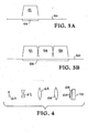
- Figure 3A shows a metal surface 40, the "top hat” intensity profile 42 of an individual pulse directed onto metal surface 40 and the strain and corresponding stress pattern 44 in the metal after peening.
- Figure 3B shows a metal surface 50 and the "top hat” intensity profile of multiple rastered pulses 52, 54 and 56 precisely spaced to produce uniform peening strain. The figure shows the uniform strain and corresponding stress pattern 58 in the metal after peening with the rastered beam. Precision overlap of multiple pulse profiles combined with the rectangular profile of the laser beam and the top hat uniform intensity profile produces a smooth surface finish after peenforming.
- Figure 4 shows an optical set up that can be used to image the near field onto the ablative layer.
- the near filed 60 is expanded in negative lens 62, is collimated by first positive lens 64 and is imaged with positive lens 66 onto the ablative layer 68 on metal piece 70.
- the imaging of the near field of the laser beam onto the absorptive layer produces a uniform intensity profile and prevents phase distortion from producing intensity hot spots.
- the laser peening technique can be used to precisely straighten components with an undesired curvature.
- An important example includes mechanical drive shafts that can acquire an unwanted bend as a result of machining, heat treatment, hardening or other manufacturing processes. By selectively applying compressive stress to the concave side of the unwanted curvature, a part can be systematically straightened.
- an unwanted curvature in drive shaft 80 is removed by peenforming on the short side of the drive shaft.
- the drive shaft 80 is provided with an absorption/ablation layer 82 and a tamping layer 84.
- a laser beam 86 is applied to the short side of the shaft and the shaft straightens as multiple pulses are applied.
- a predominately one-dimensional curvature is achieved by placing dense rows of doublely peened area on a surface with large spaces between.
- the one-dimensional nature of the peening results in a one-dimensional curvature.
- a panel such as shown in Figure 6A is further straightened in the y dimension by peening densely along the orthogonal y-dimension on the back or concave side of the curved section.
- the mechanical moment of inertia or stiffness about the axis containing the curvature increases as the part curves.
- the increased moment of inertia aids in creating the preference for one-dimensional curvature.
- the initial peening pattern is applied symmetrically and uniformly to the part so that the curvature and moments of inertia develop in a symmetric way.
Landscapes
- Engineering & Computer Science (AREA)
- Mechanical Engineering (AREA)
- Physics & Mathematics (AREA)
- Chemical & Material Sciences (AREA)
- Optics & Photonics (AREA)
- Plasma & Fusion (AREA)
- Thermal Sciences (AREA)
- Fluid Mechanics (AREA)
- Crystallography & Structural Chemistry (AREA)
- Materials Engineering (AREA)
- Metallurgy (AREA)
- Organic Chemistry (AREA)
- Laser Beam Processing (AREA)
- Non-Silver Salt Photosensitive Materials And Non-Silver Salt Photography (AREA)
- Lasers (AREA)
Abstract
Description
- This application claims priority to Provisional Patent Application Serial No. 60/144,594, titled "Contour Forming Of Metals By Means of Laser Peening," filed July 19,1999, incorporated herein by reference.
- The United States Government has rights in this invention pursuant to Contract No. W-7405-ENG-48 between the United States Department of Energy and the University of California for the operation of Lawrence Livermore National Laboratory.
- The present invention relates to laser shock processing, and more specifically, it relates to techniques for contouring metal by laser peening.
- Using high power lasers to improve material properties is one of the most important industrial applications of lasers. Lasers can transmit controllable beams of high-energy radiation for metalworking. Primarily, the laser can generate a high power density that is localized and controllable over a small area. This allows for cost effective and efficient energy utilization, minimizes distortions in surrounding areas, and simplifies material handling. Since the laser pulse involves the application of high power in short time intervals, the process is adaptable to high-speed manufacturing. The fact that the beam can be controlled allows parts having complex shapes to be processed. Also accuracy, consistency, and repeatability are inherent to the system.
- Improving the strength of metals by cold working undoubtedly was discovered early in civilization, as ancient man hammered out his weapons and tools. Since the 1950s, shot peening has been used as a means to improve the fatigue properties of metals. Another method of shock processing involves the use of high explosive materials in contact with the metal surface.
- The use of high intensity laser outputs for the generation of mechanical shock waves to treat the surfaces of metals has been well known since the 1970s. The laser shock process can be used to generate compressive stresses in the metal surfaces adding strength and resistance to corrosive failure.
- Lasers with pulse outputs of 10to 100 J and pulse durations of 10 to 100 ns are useful for generating inertially confined plasmas on the surfaces of metals. These plasmas create pressures in the range of 10,000 to 100,000 atmospheres and the resulting shock pressure can exceed the elastic limit of the metal and thus compressively stress a surface layer as deep or deeper than 1 mm in the metals. Lasers are now becoming available with average power output meaningful for use of the technique at a rate appropriate for industrial production.
- In the process of laser shock processing, a metal surface to be treated is painted or otherwise made "black" that is, highly absorbing of the laser light. The black layer both acts as an absorber of the laser energy and protects the surface of the part from laser ablation and from melting due to the high temperature of the plasma. A thin layer of water, typically 1 to 2 mm, is flowed over this black surface. The water acts to inertially confine or, as it is called, tamp the plasma generated as the laser energy is absorbed in the short time pulse duration, typically 30 ns. Other suitable materials that act as a tamper are also possible. A limitation to the usefulness of the process is the ability to deliver the laser energy to the metal surface in a spatially uniform beam. If not uniform, the highest intensity area of the light can cause a breakdown in the water which blocks delivery of meaningful energy to the painted metal surface. A conventional technique to deliver the laser light to the surface is to use a simple lens to condense the laser output to a power density of roughly 100 J to 200 J per square centimeter. This condensing technique has the limitation that a true "image" of the laser near-field intensity profile is not obtained at the surface. Rather a field intensity representing something between the near and far fields is generated. Diffraction of the laser beam as it is focused down onto the surface results in very strong spatial modulation and hot spots.
- Any phase aberrations generated within the beam, especially those associated with operation of the laser for high average power, can propagate to generate higher intensity areas within the beam. These high peak intensity regions cause breakdown in the water layer, preventing efficient delivery of the laser energy to the surface to be treated. Another potential cause of breakdown in the tamping material is the generation of non-linear effects such as optical breakdown and stimulated scattering. In a normal generation of a 10 ns to 100 ns pulse within a laser, the output slowly builds over a time period exceeding several pulsewidths. This slow, weak intensity helps to seed the non-linear processes that require buildup times of 10s of nanoseconds. In conventional techniques, the pulse output of the laser is "sliced" by an external means such as a fast rising electro-optical switch or by an exploding foil. These techniques can be expensive and can limit reliability.
- A controlled application of compressive stress applied to one side of a metal surface will cause that surface to expand in a predictable manner
and can thus curve the metal in a highly controllable fashion. Upon curving, the convex surface is left with a residual compressive stress which
is highly desirable for fatigue and corrosion resistance of the part in operation. The technique of inducing this compressive stress by means of
shot peening is well known and in general use. However, shot peening is
limited in the depth of intense compressive stress that can be induced without generating significant and undesirable cold working of the surface
layer. Due to the required spherical shape of shot used for peening, the process imparts a non-uniform pressure vs. time profile to the metal during each individual impact of the shot. Pressure is initiated at the first contact point of the sphere and then spreads across the impact area as the metals deform and the entire cross-section of the shot contacts the metal. This non-uniform application of pressure results in a local extrusion of the metal, a flow of metal from the center to the outer area of the impact zone. Consequently, more cold work is done on the metal as material extrudes due to the wedge of pressure created by the impact of the shot. - U.S. Patent No. 4,694,672, titled "Method And Apparatus For Imparting A Simple Contour To A Workpiece," is directed to a conventional method and apparatus for imparting a simple contour to an aircraft skin. A treatment chamber has a conveyor with a workpiece attached thereto and includes a shot peening blast unit for treatment of the workpiece. A control system is provided for orienting the workpiece and blast unit so that the peening is done only in narrow spanwise strips and only on common chord percentage lines of the workpiece. This method and apparatus thereby creates chordwise simple curvature to the workpiece while minimizing compound curvature effects. See also U.S. Patent No. Patent 3,668,912.
- In U.S. Patent No. 4,329,862, titled "Shot Peen Forming Of Compound Contours," a flat sheet metal part is conventionally shot peened on both sides. The part is shot peened on one side with an intensity programmed to vary in a pattern for matching the part to a chordwise curvature, and the part takes on the compound curvature of an aircraft wing surface.
- It would be desirable if a laser process could achieve an intense stress much deeper into the part and thus effect greater curvature of thicker
parts. It would additionally be desirable if the laser process could generate negligible cold work and thus leave a very smooth surface finish. - It is an object of the present invention to provide a laser peening process that can achieve an intense stress much deeper into the part and thus effect greater curvature of thicker metal sections.
- The invention is a method and apparatus for forming shapes and contours in metal sections by generating laser induced compressive stress on the surface of the metal workpiece. The laser process can generate deep compressive stresses to shape even thick components without inducing unwanted tensile stress at the metal surface. The precision of the laser-induced stress enables exact prediction and subsequent contouring of parts.
- In the present invention, a light beam of 10 to 100J/pulse is imaged to create an energy fluence of 60 to 200 J/cm2 on an absorptive layer applied over a metal surface. Typically, water is flowed over the absorptive layer. The absorption of laser light causes a plasma to form and consequently creates a shock wave that induces a deep residual compressive stress into the metal. The metal responds to this residual stress by bending.
- It is a well-known concept to use a mechanical means to contour thin metal components. The concept of using a laser to generate shock waves that induce a compressive stress into metals is widely practiced for improving the resistance of metal components to fatigue cracking and corrosion. The present invention applies a laser-induced shock to one side of a metal workpiece to produce a precise local curvature. By applying the shock more generally over a broader area, or multiple times over the same area, larger scale curvatures are achieved. This invention employs a high energy, high average power laser, set to operate at specific parameters to achieve precise shaping of components. This laser peen forming process is especially useful for thick (greater than 3/4 inch thick) material that is difficult to shape or contour.
- The metal is covered with a layer of material that absorbs the laser light. A thin layer of water is flowed over the absorptive material and illuminated by the laser. By sequentially applying laser pulses in a raster scan fashion, compressive stress is induced over the illuminated surface. The stress will in turn generate a strain of the top layer of metal and produce a curvature to the material. The intensity and depth of compressive stress applied to each local area can be controlled by selecting the laser energy, laser pulse footprint and overlap, the pulse duration and the number of pulses applied to each area. The part can be precisely contoured over its larger area by systematically applying impulses of local stress thereover. Additional control of two-dimensional curvature can be achieved by the specific density in which pulses are placed on the surface that becomes convex, by placing compensating pulses on the surface that becomes concave and by taking advantage of the increasing mechanical moment of inertia generated within the part as a component changes to a curved shape.
- The laser peening technique can also be used to precisely straighten components that have an undesired curvature. An important example includes mechanical drive shafts that can acquire an unwanted bend as a result of machining, heat treatment, hardening or other manufacturing processes. By selectively applying compressive stress to the concave side of the unwanted curvature, a part can be systematically straightened.
- In contrast to shot peening, the highly uniform laser intensity profile (when using a tailored beam with flat top profile and imaging this profile onto the part) impacts the metal uniformly over the entire impact area resulting in a "blunt" force that causes little extrusion of metal and little cold work. Thus the laser peen forming process can produce a greater volume of stressed metal with little cold work. Relatively large curvatures can be impressed into thick metal sections without severely distorting the metal surface.
-
- Figure 1A shows a flat metal plate.
- Figure 1B shows the curvature produced in the metal plate after application of the laser peening process to its top surface.
- Figure 2 illustrates the set up of the laser beam and tamping layer with respect to the metal substrate and the absorptive layer.
- Figure 3A shows the "top hat" intensity profile of an individual pulse directed onto a metal surface and the strain and corresponding stress pattern produced in the metal after peening.
- Figure 3B shows the "top hat" intensity profile of multiple rastered pulses precisely spaced to produce uniform peening strain and the uniform strain and corresponding stress pattern in the metal after peening with the rastered beam.
- Figure 4 shows the means for imaging the laser near field onto the absorptive layer on a metal surface.
- Figure 5 illustrates the removal of unwanted curvature in a drive shaft by laser peening.
- Figure 6A illustrates the production of a predominately one-dimensional curvature by placing dense rows of doublely peened area on a surface with large spaces between.
- Figure 6B shows a panel such as shown in Figure 6A that is further straightened in the y dimension by peening densely along the orthogonal y-dimension on the back or concave side of the curved section.
- Techniques for laser peening are disclosed in co-pending U.S. Patent Application Serial No. 09/133,590, titled "Laser Beam Temporal And Spatial Tailoring For Laser Shock Processing", incorporated herein by reference. Laser technology usable in the present invention is described in U.S. Patent No. 5,285,310 titled "High Power Regenerative Laser Amplifier," incorporated herein by reference, and U.S. Patent No. 5,239,408 titled "High Power, High Beam Quality Regenerative Amplifier," also incorporated herein by reference. Embodiments of laser systems usable in the present invention are described in U.S. Patent No. 5,689,363 titled "Long Pulse Width, Narrow-Bandwidth Solid State Laser" incorporated herein by reference.
- A process for forming shapes and contdurs in metal sections involves the use of laser induced compressive stress generated on the surface of the
metal. The laser process can generate deep compressive stresses which greatly aid in the shaping of thick components without inducing unwanted tensile stress at the metal surface. The precision of the laser induced stress enables exact prediction and subsequent contouring of parts. - Precision forming and shaping of metal components without inducing
undesirable tensile stress has important uses in DOD and commercial applications, especially in aircraft and aerospace components. The ability to form thick (3/4" to 1" or thicker) metal sections will revolutionize how these thick sections are formed for airplane components such as wing skins. This technique will make it possible to form parts that otherwise could not be formed. - As required, detailed embodiments of the present invention are disclosed herein. However, it is to be understood that the disclosed embodiments are merely exemplary of the present invention that may be embodied in various systems. Therefore, specific details disclosed herein are not to be interpreted as limiting, but rather as a basis for the claims and as a representative basis for teaching one skilled in the art to variously practice the present invention.
- It is a well known concept to use a mechanical means, such as a peening hammer or more recently, the technique of shot peening, to contour and
shape thin metal components. A compressive stress is "hammered" into the
metal and the metal subsequently expands on one side to relieve this stress. The differential expansion causes the metal surface to curve. The
concept of using a laser to generate shock waves that induce a compressive
stress into metals is well known and becoming fairly widely practiced for improving the resistance of metal components to fatigue cracking and corrosion. - By appropriately applying the laser induced shock to one side of the metal a precise local curvature can be achieved and by applying the shock more generally over a broader area, larger scale curvature can be achieved. This invention employs a high energy, high average power laser, set to operate at specific parameters to achieve precise shaping of components. This laser peen forming process is especially useful for thick (greater than 3/4 inch thick) material that is difficult to shape or contour. Figure 1A shows a
flat metal plate 10. After application of the laser peening process to itstop surface 12, the metal plate achieves a desired curvature, as shown in Figure 1B. - One embodiment of the present invention, illustrated in Figure 2, uses a 25 J per pulse laser (25 J to 100 J per pulse is the appropriate range), with a pulse duration of 10 to 20 ns and a rising edge on the pulse of less than 1 ns. The near field is imaged to a spot size (ranging from 6 mm x 6 mm to 3 mm x 3 mm) giving an energy fluence of between 60 to 200 J/cm2 at the
metal surface 20. The metal is covered with a layer of material 22 (typically an polyvinylacetate plastic approximately 200 µm thick) that absorbs the laser light. A tamping layer, typically a thin layer ofwater 24 from a flow nozzle 26, approximately 1 mm thick is typically flowed over theabsorptive material 22 and is illuminated by thelaser beam 28. By sequentially applying laser pulses in a raster scan fashion, compressive stress will be induced over the surface illuminated. Thelaser beam 28 or themetal component 30 can be moved to achieve the rastered pattern. The stress will in turn generate a strain on the top layer ofmetal 30 and produce a curvature to the material. The intensity and depth of compressive stress applied to each local area can be controlled by selecting the laser energy, laser pulse footprint and overlap, the pulse duration and the number of pulses applied to each area. Two-dimensional curvature can be achieved by selectively controlling the area peened and the intensity and number of pulses used in each coordinate direction. Additionally, deformation in any desired direction can be enhanced by mechanically inducing a bending moment (although below the yield limit of the metal) in that direction during application of the laser peenforming pulses. - Because the locally applied stress will directly effect the local curvature, the part can be precisely contoured over its larger area by systematically applying impulses of local stress over the large area. Figure 3A shows a metal surface 40, the "top hat"
intensity profile 42 of an individual pulse directed onto metal surface 40 and the strain andcorresponding stress pattern 44 in the metal after peening. Figure 3B shows ametal surface 50 and the "top hat" intensity profile of multiplerastered pulses corresponding stress pattern 58 in the metal after peening with the rastered beam. Precision overlap of multiple pulse profiles combined with the rectangular profile of the laser beam and the top hat uniform intensity profile produces a smooth surface finish after peenforming. - Figure 4 shows an optical set up that can be used to image the near field onto the ablative layer. The near filed 60 is expanded in
negative lens 62, is collimated by firstpositive lens 64 and is imaged withpositive lens 66 onto theablative layer 68 onmetal piece 70. The imaging of the near field of the laser beam onto the absorptive layer produces a uniform intensity profile and prevents phase distortion from producing intensity hot spots. - In an analogous way to achieving desired shapes in nominally flat metal, the laser peening technique can be used to precisely straighten components with an undesired curvature. An important example includes mechanical drive shafts that can acquire an unwanted bend as a result of machining, heat treatment, hardening or other manufacturing processes. By selectively applying compressive stress to the concave side of the unwanted curvature, a part can be systematically straightened. Referring to Figure 5, an unwanted curvature in
drive shaft 80 is removed by peenforming on the short side of the drive shaft. Thedrive shaft 80 is provided with an absorption/ablation layer 82 and a tamping layer 84. A laser beam 86 is applied to the short side of the shaft and the shaft straightens as multiple pulses are applied. - In Figure 6A, a predominately one-dimensional curvature is achieved by placing dense rows of doublely peened area on a surface with large spaces between. The one-dimensional nature of the peening results in a one-dimensional curvature. In Figure 6B, a panel such as shown in Figure 6A is further straightened in the y dimension by peening densely along the orthogonal y-dimension on the back or concave side of the curved section. Finally it is recognized that the mechanical moment of inertia or stiffness about the axis containing the curvature (x-axis in our example) increases as the part curves. By applying the two techniques discussed above, the increased moment of inertia aids in creating the preference for one-dimensional curvature. The initial peening pattern is applied symmetrically and uniformly to the part so that the curvature and moments of inertia develop in a symmetric way.
- The foregoing description of the invention has been presented for purposes of illustration and description and is not intended to be exhaustive or to limit the invention to the precise form disclosed. Many modifications and variations are possible in light of the above teaching. The embodiments were chosen and described to best explain the principles of the invention and its practical application to thereby enable others skilled in the art to best use the invention in various embodiments and with various modifications suited to the particular use contemplated. The scope of the invention is to be defined by the following claims.
Claims (5)
- A system for forming shapes and contours in a metal workpiece, comprising:a laser system that is capable of producing a series of laser pulses, wherein each laser pulse of said series of laser pulses has an energy within a range of 10 J to 100 J per pulse, wherein said each laser pulse has a pulse duration within a range of 10 ns to 20 ns and a rising edge that is less than 1 ns;a layer of material that absorbs light for fixedly attaching to a metal workpiece and comprising polyvinyl acetate or polyvinyl chloride plastic;means for flowing a thin layer of water over said layer of material; andmeans for imaging the near field of said each laser pulse to a spot size on said layer of material so that said series of laser pulses will generate compressive stress on the surface of said metal workpiece until a desired shape is formed therein without inducing unwanted tensile stress at the surface of said metal workpiece.
- The apparatus of claim 1, wherein said means for imaging the near field of said each laser pulse images said each laser pulse to a spot size to provide an energy fluence of between 60 and 200 J/cm2 at the surface of said metal workpiece.
- The apparatus of claim 1, wherein said layer of material is approximately 200 µm thick.
- The apparatus of claim 1, wherein said thin layer of water is approximately 1 mm thick.
- The apparatus of claim 1, further comprising means for sequentially applying laser pulses in a raster scan fashion on the surface of said metal workpiece, wherein compressive stress will be induced over the surface illuminated, wherein said compressive stress will in turn generate a strain of the top layer of said metal workpiece and produce a curvature in said metal workpiece.
Applications Claiming Priority (2)
| Application Number | Priority Date | Filing Date | Title |
|---|---|---|---|
| US14459499P | 1999-07-19 | 1999-07-19 | |
| EP00975148A EP1212472B1 (en) | 1999-07-19 | 2000-06-26 | Contour forming of metals by laser peening |
Related Parent Applications (2)
| Application Number | Title | Priority Date | Filing Date |
|---|---|---|---|
| EP00975148.8 Division | 2000-06-26 | ||
| EP00975148A Division EP1212472B1 (en) | 1999-07-19 | 2000-06-26 | Contour forming of metals by laser peening |
Publications (2)
| Publication Number | Publication Date |
|---|---|
| EP1627929A1 true EP1627929A1 (en) | 2006-02-22 |
| EP1627929B1 EP1627929B1 (en) | 2010-08-18 |
Family
ID=22509280
Family Applications (2)
| Application Number | Title | Priority Date | Filing Date |
|---|---|---|---|
| EP05021795A Expired - Lifetime EP1627929B1 (en) | 1999-07-19 | 2000-06-26 | Contour forming of metals by laser peening |
| EP00975148A Expired - Lifetime EP1212472B1 (en) | 1999-07-19 | 2000-06-26 | Contour forming of metals by laser peening |
Family Applications After (1)
| Application Number | Title | Priority Date | Filing Date |
|---|---|---|---|
| EP00975148A Expired - Lifetime EP1212472B1 (en) | 1999-07-19 | 2000-06-26 | Contour forming of metals by laser peening |
Country Status (13)
| Country | Link |
|---|---|
| US (1) | US6410884B1 (en) |
| EP (2) | EP1627929B1 (en) |
| JP (2) | JP4215981B2 (en) |
| KR (1) | KR100650118B1 (en) |
| CN (1) | CN1228460C (en) |
| AT (2) | ATE478160T1 (en) |
| AU (1) | AU1323901A (en) |
| CA (1) | CA2379959C (en) |
| DE (2) | DE60024840T2 (en) |
| ES (2) | ES2356461T3 (en) |
| PL (1) | PL195102B1 (en) |
| RU (1) | RU2228234C2 (en) |
| WO (1) | WO2001005549A2 (en) |
Cited By (2)
| Publication number | Priority date | Publication date | Assignee | Title |
|---|---|---|---|---|
| CN110653484A (en) * | 2018-06-28 | 2020-01-07 | 大族激光科技产业集团股份有限公司 | Method, electronic device and laser marking machine for improving scratch resistance of glass fiber reinforced plastic surface |
| CN113305420A (en) * | 2021-06-09 | 2021-08-27 | 广东工业大学 | Complex hyperbolic torsional curved surface dieless forming method and device |
Families Citing this family (60)
| Publication number | Priority date | Publication date | Assignee | Title |
|---|---|---|---|---|
| US6001229A (en) * | 1994-08-01 | 1999-12-14 | Lockheed Martin Energy Systems, Inc. | Apparatus and method for performing microfluidic manipulations for chemical analysis |
| US6670578B2 (en) | 1999-07-19 | 2003-12-30 | The Regents Of The University Of California | Pre-loading of components during laser peenforming |
| SE0000570L (en) * | 2000-02-22 | 2001-08-23 | Avesta Sheffield Ab | Subject-controlled shaping |
| US6818854B2 (en) * | 2001-09-14 | 2004-11-16 | The Regents Of The University Of California | Laser peening with fiber optic delivery |
| US7097720B2 (en) * | 2003-04-30 | 2006-08-29 | General Electric Company | Lower fluence boundary laser shock peening |
| US8049137B2 (en) * | 2004-02-13 | 2011-11-01 | Boston Scientific Scimed, Inc. | Laser shock peening of medical devices |
| US20050205529A1 (en) * | 2004-03-22 | 2005-09-22 | The Regents Of The University Of California | Calibration system for laser peening |
| JP4605700B2 (en) * | 2004-07-28 | 2011-01-05 | 武蔵精密工業株式会社 | Correction method of tooth trace on tooth surface of gear |
| US7750266B2 (en) * | 2004-11-17 | 2010-07-06 | Metal Improvement Company Llc | Active beam delivery system for laser peening and laser peening method |
| JP4690895B2 (en) * | 2005-01-11 | 2011-06-01 | 新日本製鐵株式会社 | Laser peening treatment method of metal object and metal object manufactured by laser peening treatment method |
| US7723643B2 (en) * | 2005-04-06 | 2010-05-25 | Lawrence Livermore National Security, Llc | Laser peening for reducing hydrogen embrittlement |
| US7412300B2 (en) * | 2005-07-27 | 2008-08-12 | General Electric Company | Thermal forming |
| US9409254B2 (en) * | 2005-09-30 | 2016-08-09 | Lawrence Livermore National Security, Llc | Ablation layers to prevent pitting in laser peening |
| JP4658832B2 (en) * | 2006-03-06 | 2011-03-23 | 新日本製鐵株式会社 | Laser peening treatment method of metal object and metal object |
| US8330070B2 (en) | 2006-05-11 | 2012-12-11 | Kabushiki Kaisha Toshiba | Laser shock hardening method and apparatus |
| PL2164674T3 (en) * | 2007-06-18 | 2017-07-31 | Donadon Safety Discs And Devices S.R.L. | Method for production of safety /rupture discs having pre-calculated breaking threshold |
| US8084710B2 (en) * | 2008-03-07 | 2011-12-27 | The Ohio State University | Low-temperature laser spot impact welding driven without contact |
| JP5654219B2 (en) * | 2009-07-14 | 2015-01-14 | 富士重工業株式会社 | Rotating tool for friction stir welding |
| US10072971B2 (en) | 2010-04-16 | 2018-09-11 | Metal Improvement Company, Llc | Flexible beam delivery system for high power laser systems |
| CN101920397B (en) * | 2010-04-16 | 2013-01-23 | 江苏大学 | Diffractive micro-optical element-based intense laser die-free forming method and device |
| DE102010019258B4 (en) * | 2010-05-03 | 2014-12-11 | Thyssenkrupp Steel Europe Ag | Process for the production of tailor-made hot-stamped sheet steel products and sheet steel product |
| RU2475322C1 (en) * | 2011-05-31 | 2013-02-20 | Открытое акционерное общество "Комсомольское-на-Амуре авиационное производственное объединение имени Ю.А. Гагарина" | Method of forming |
| CN102513697A (en) * | 2011-12-29 | 2012-06-27 | 江苏大学 | Preparation method for simulated surfaces |
| CN103302406B (en) * | 2013-06-20 | 2015-03-11 | 江苏大学 | Intra-light water delivery laser shock peening method and device |
| US9539690B2 (en) | 2013-09-19 | 2017-01-10 | The Boeing Company | Control feedback loop for real-time variable needle peen forming |
| US10576523B1 (en) | 2013-09-19 | 2020-03-03 | The Boeing Company | Method and apparatus for impacting metal parts |
| US8997545B1 (en) | 2013-09-19 | 2015-04-07 | The Boeing Company | Method and apparatus for impacting metal parts for aerospace applications |
| US10239155B1 (en) * | 2014-04-30 | 2019-03-26 | The Boeing Company | Multiple laser beam processing |
| CN104164554A (en) * | 2014-07-16 | 2014-11-26 | 江苏大学 | Method for reinforcement of metal surface by large area laser shock |
| US20160016255A1 (en) * | 2014-07-17 | 2016-01-21 | Siemens Energy, Inc. | Laser correction of metal deformation |
| CN104480476B (en) * | 2014-11-12 | 2017-02-22 | 江苏大学 | Laser thermal combination remanufacturing method for metal damage part |
| EP3025809B1 (en) * | 2014-11-28 | 2017-11-08 | Ansaldo Energia IP UK Limited | Method for manufacturing a component using an additive manufacturing process |
| US20160236296A1 (en) * | 2015-02-13 | 2016-08-18 | Gold Nanotech Inc | Nanoparticle Manufacturing System |
| CN104911520B (en) * | 2015-05-28 | 2017-12-05 | 湖北工业大学 | A kind of method that aluminium alloy super-hydrophobic automatic cleaning surface is prepared using short-pulse laser |
| CN104911329A (en) * | 2015-05-28 | 2015-09-16 | 湖北工业大学 | Method for preparation of stainless steel superhydrophobic corrosion-resistant surface by use of ultrashort pulse laser |
| CN105290617B (en) * | 2015-11-13 | 2017-05-31 | 中国科学院力学研究所 | A kind of processing and treating method for making glassy metal produce stretching plastic |
| US10406583B2 (en) | 2015-12-10 | 2019-09-10 | The Boeing Company | Apparatus, system, and method for forming metal parts |
| EP3512664A1 (en) | 2016-06-13 | 2019-07-24 | Mores, Stylianos | Electromagnetic hammer device for the mechanical treatment of materials and method of use thereof |
| CN106216445B (en) * | 2016-07-12 | 2018-02-06 | 广东工业大学 | A kind of large thin-wall element laser peening straightening method with complex surface |
| KR102357445B1 (en) * | 2016-09-23 | 2022-01-28 | 타타 스틸 네덜란드 테크날러지 베.뷔. | Method and apparatus for liquid-assisted laser texturing of moving steel strips |
| PL3523083T3 (en) * | 2016-11-18 | 2024-02-05 | Ipg Photonics Corporation | System and method for laser processing of materials. |
| CN106694724B (en) * | 2016-12-19 | 2019-04-19 | 上海交通大学 | Flexible Prestressed Fixture for Shot Peening of Large Wall Panel Workpieces |
| WO2019067531A1 (en) * | 2017-09-26 | 2019-04-04 | Apex Brands, Inc. | Measuring tape with increased cupping |
| US10989512B2 (en) | 2017-09-26 | 2021-04-27 | Apex Brands, Inc. | Measuring tape with improved standout |
| JP7096000B2 (en) | 2018-01-30 | 2022-07-05 | 浜松ホトニクス株式会社 | Laser processing equipment and laser processing method |
| US11413729B2 (en) * | 2018-08-20 | 2022-08-16 | Milwaukee Electric Tool Corporation | Tool bit |
| CN109271711B (en) * | 2018-09-25 | 2023-03-28 | 重庆大学 | Finite element modeling method for carburizing and hardening gear considering uneven characteristics |
| US11433624B2 (en) * | 2019-03-28 | 2022-09-06 | Spirit Aerosystems, Inc. | Peen-forming of thermoplastic composite material |
| CN110802218B (en) * | 2019-10-21 | 2021-02-09 | 苏州科技大学 | Rapid creep aging forming method for large-curvature corrugated plate |
| CN111975206B (en) * | 2020-07-15 | 2022-05-20 | 江苏大学 | Laser impact curved surface imprinting and curved surface micro-morphology repairing process |
| US20220176495A1 (en) * | 2020-12-04 | 2022-06-09 | Lawrence Livermore National Security, Llc | System and method for radius of curvature modification of optical plates and lenses by irradiation with optical energy |
| WO2022144809A1 (en) * | 2020-12-31 | 2022-07-07 | Дмитрий ЧУХЛАНЦЕВ | Method for the laser shock peening of parts |
| CN114378448B (en) * | 2021-12-15 | 2024-05-24 | 富联裕展科技(深圳)有限公司 | Metal part manufacturing method, metal part and metal product |
| CN114700627B (en) * | 2022-05-13 | 2023-06-06 | 西安交通大学 | Laser shock liquid constraint layer thickness control system |
| CN115090751B (en) * | 2022-07-14 | 2024-04-05 | 中国航空制造技术研究院 | Method for improving shot blasting forming limit of ribbed integral wallboard |
| CN116372010B (en) * | 2023-03-16 | 2025-08-08 | 宁波大学 | Auxiliary creep age forming method for realizing high-precision preforming by laser impact |
| EP4450653A1 (en) | 2023-04-19 | 2024-10-23 | Airbus Operations GmbH | Method and working station for peening forming treatment |
| US12337415B2 (en) * | 2023-05-31 | 2025-06-24 | Applied Materials, Inc. | Method and apparatus for laser texturing a component |
| CN118186202B (en) * | 2024-03-18 | 2024-11-01 | 江苏大学 | Strengthening method and device for magnetostatic field coupling laser impact ferromagnetic metal |
| US20260015736A1 (en) * | 2024-07-09 | 2026-01-15 | Rtx Corporation | Laser clean after diffusion heat treat and prior to shot peen |
Citations (8)
| Publication number | Priority date | Publication date | Assignee | Title |
|---|---|---|---|---|
| US4694672A (en) * | 1984-01-05 | 1987-09-22 | Baughman Davis L | Method and apparatus for imparting a simple contour to a workpiece |
| JPH01313113A (en) * | 1988-06-13 | 1989-12-18 | Fujitsu Ltd | Bending method for sheet metal by laser beam |
| US5072606A (en) * | 1988-12-14 | 1991-12-17 | Dornier Gmbh | Peening shot curving |
| US5235838A (en) * | 1987-07-13 | 1993-08-17 | W. Hegenscheidt Gesellschaft Mbh | Method and apparatus for truing or straightening out of true work pieces |
| US5531570A (en) * | 1995-03-06 | 1996-07-02 | General Electric Company | Distortion control for laser shock peened gas turbine engine compressor blade edges |
| US5674329A (en) | 1996-04-26 | 1997-10-07 | General Electric Company | Adhesive tape covered laser shock peening |
| US5742028A (en) | 1996-07-24 | 1998-04-21 | General Electric Company | Preloaded laser shock peening |
| US5951790A (en) * | 1998-06-26 | 1999-09-14 | General Electric Company | Method of monitoring and controlling laser shock peening using an in plane deflection test coupon |
Family Cites Families (44)
| Publication number | Priority date | Publication date | Assignee | Title |
|---|---|---|---|---|
| US4937421A (en) | 1989-07-03 | 1990-06-26 | General Electric Company | Laser peening system and method |
| US5492447A (en) | 1994-10-06 | 1996-02-20 | General Electric Company | Laser shock peened rotor components for turbomachinery |
| US5522706A (en) | 1994-10-06 | 1996-06-04 | General Electric Company | Laser shock peened disks with loading and locking slots for turbomachinery |
| US5846054A (en) | 1994-10-06 | 1998-12-08 | General Electric Company | Laser shock peened dovetails for disks and blades |
| US6215097B1 (en) | 1994-12-22 | 2001-04-10 | General Electric Company | On the fly laser shock peening |
| US5591009A (en) | 1995-01-17 | 1997-01-07 | General Electric Company | Laser shock peened gas turbine engine fan blade edges |
| US5584662A (en) | 1995-03-06 | 1996-12-17 | General Electric Company | Laser shock peening for gas turbine engine vane repair |
| US5525429A (en) | 1995-03-06 | 1996-06-11 | General Electric Company | Laser shock peening surface enhancement for gas turbine engine high strength rotor alloy repair |
| US5620307A (en) | 1995-03-06 | 1997-04-15 | General Electric Company | Laser shock peened gas turbine engine blade tip |
| US5569018A (en) | 1995-03-06 | 1996-10-29 | General Electric Company | Technique to prevent or divert cracks |
| US5744781A (en) | 1995-08-07 | 1998-04-28 | General Electric Company | Method and apparatus for laser shock peening |
| US5741559A (en) * | 1995-10-23 | 1998-04-21 | Lsp Technologies, Inc. | Laser peening process and apparatus |
| US6057003A (en) * | 1995-10-23 | 2000-05-02 | Lsp Technologies, Inc. | Peening process with reduction of dielectric breakdown to increase peak pressure pulse |
| US5735044A (en) | 1995-12-12 | 1998-04-07 | General Electric Company | Laser shock peening for gas turbine engine weld repair |
| US5671628A (en) | 1995-12-18 | 1997-09-30 | General Electric Company | Laser shock peened dies |
| US5730811A (en) | 1995-12-21 | 1998-03-24 | General Electric Company | Cavity dumped laser shock peening process |
| US5584586A (en) | 1996-03-04 | 1996-12-17 | General Electric Company | Laser shock peened bearings |
| JPH09277069A (en) * | 1996-04-12 | 1997-10-28 | Komatsu Ltd | Liquid crystal mask, liquid crystal laser marker, and marking method using the same |
| US5674328A (en) | 1996-04-26 | 1997-10-07 | General Electric Company | Dry tape covered laser shock peening |
| JPH10153750A (en) * | 1996-11-25 | 1998-06-09 | Sumitomo Electric Ind Ltd | Laser beam shaping optics |
| US6002102A (en) | 1997-02-25 | 1999-12-14 | Lsp Technologies, Inc. | Hidden surface laser shock processing |
| US5911890A (en) | 1997-02-25 | 1999-06-15 | Lsp Technologies, Inc. | Oblique angle laser shock processing |
| US5910651A (en) * | 1997-07-15 | 1999-06-08 | Gerber Systems Corporation | Method and apparatus for image nonlinearity compensation in scanning systems |
| US5852621A (en) * | 1997-07-21 | 1998-12-22 | Cymer, Inc. | Pulse laser with pulse energy trimmer |
| US5988982A (en) | 1997-09-09 | 1999-11-23 | Lsp Technologies, Inc. | Altering vibration frequencies of workpieces, such as gas turbine engine blades |
| US5911891A (en) | 1997-09-11 | 1999-06-15 | Lsp Technologies, Inc. | Laser shock peening with tailored multiple laser beams |
| US5935464A (en) | 1997-09-11 | 1999-08-10 | Lsp Technologies, Inc. | Laser shock peening apparatus with a diffractive optic element |
| US5980101A (en) | 1997-10-31 | 1999-11-09 | General Electric Company | Method and apparatus for measuring laser pulse energy |
| US5987042A (en) | 1997-10-31 | 1999-11-16 | General Electric Company | Method and apparatus for shaping a laser pulse |
| US6144012A (en) | 1997-11-05 | 2000-11-07 | Lsp Technologies, Inc. | Efficient laser peening |
| US6021154A (en) | 1997-11-21 | 2000-02-01 | General Electric Company | Laser shock peening method and reflective laser beam homogenizer |
| JP3191918B2 (en) * | 1997-11-25 | 2001-07-23 | 株式会社小松製作所 | Semiconductor wafer with microdot marks |
| US5932120A (en) | 1997-12-18 | 1999-08-03 | General Electric Company | Laser shock peening using low energy laser |
| US6005219A (en) | 1997-12-18 | 1999-12-21 | General Electric Company | Ripstop laser shock peening |
| US6078022A (en) | 1997-12-30 | 2000-06-20 | Lsp Technologies, Inc. | Laser peening hollow core gas turbine engine blades |
| US6064035A (en) | 1997-12-30 | 2000-05-16 | Lsp Technologies, Inc. | Process chamber for laser peening |
| US6002706A (en) | 1997-12-30 | 1999-12-14 | General Electric Company | Method and apparatus for controlling the size of a laser beam |
| US5987991A (en) | 1998-01-02 | 1999-11-23 | General Electric Company | Determination of Rayleigh wave critical angle |
| US6130400A (en) | 1998-06-26 | 2000-10-10 | General Electric Company | Ballistic momentum apparatus and method for monitoring and controlling laser shock peening |
| US6198069B1 (en) * | 1998-08-13 | 2001-03-06 | The Regents Of The University Of California | Laser beam temporal and spatial tailoring for laser shock processing |
| US5948293A (en) | 1998-12-03 | 1999-09-07 | General Electric Company | Laser shock peening quality assurance by volumetric analysis of laser shock peened dimple |
| US6049058A (en) | 1998-12-15 | 2000-04-11 | Lsp Technologies, Inc. | Laser peening process and apparatus with uniform pressure pulse confinement |
| US6155789A (en) | 1999-04-06 | 2000-12-05 | General Electric Company | Gas turbine engine airfoil damper and method for production |
| US6075593A (en) | 1999-08-03 | 2000-06-13 | General Electric Company | Method for monitoring and controlling laser shock peening using temporal light spectrum analysis |
-
2000
- 2000-06-26 AT AT05021795T patent/ATE478160T1/en not_active IP Right Cessation
- 2000-06-26 PL PL00354627A patent/PL195102B1/en unknown
- 2000-06-26 EP EP05021795A patent/EP1627929B1/en not_active Expired - Lifetime
- 2000-06-26 ES ES05021795T patent/ES2356461T3/en not_active Expired - Lifetime
- 2000-06-26 EP EP00975148A patent/EP1212472B1/en not_active Expired - Lifetime
- 2000-06-26 JP JP2001510619A patent/JP4215981B2/en not_active Expired - Lifetime
- 2000-06-26 AT AT00975148T patent/ATE312950T1/en not_active IP Right Cessation
- 2000-06-26 ES ES00975148T patent/ES2253271T3/en not_active Expired - Lifetime
- 2000-06-26 DE DE60024840T patent/DE60024840T2/en not_active Expired - Lifetime
- 2000-06-26 CA CA2379959A patent/CA2379959C/en not_active Expired - Lifetime
- 2000-06-26 WO PCT/US2000/017669 patent/WO2001005549A2/en not_active Ceased
- 2000-06-26 US US09/604,781 patent/US6410884B1/en not_active Expired - Lifetime
- 2000-06-26 CN CNB008104271A patent/CN1228460C/en not_active Expired - Lifetime
- 2000-06-26 AU AU13239/01A patent/AU1323901A/en not_active Abandoned
- 2000-06-26 DE DE60044856T patent/DE60044856D1/en not_active Expired - Lifetime
- 2000-06-26 KR KR1020027000662A patent/KR100650118B1/en not_active Expired - Lifetime
- 2000-06-26 RU RU2002104019/02A patent/RU2228234C2/en active
-
2007
- 2007-02-05 JP JP2007026019A patent/JP5000323B2/en not_active Expired - Lifetime
Patent Citations (8)
| Publication number | Priority date | Publication date | Assignee | Title |
|---|---|---|---|---|
| US4694672A (en) * | 1984-01-05 | 1987-09-22 | Baughman Davis L | Method and apparatus for imparting a simple contour to a workpiece |
| US5235838A (en) * | 1987-07-13 | 1993-08-17 | W. Hegenscheidt Gesellschaft Mbh | Method and apparatus for truing or straightening out of true work pieces |
| JPH01313113A (en) * | 1988-06-13 | 1989-12-18 | Fujitsu Ltd | Bending method for sheet metal by laser beam |
| US5072606A (en) * | 1988-12-14 | 1991-12-17 | Dornier Gmbh | Peening shot curving |
| US5531570A (en) * | 1995-03-06 | 1996-07-02 | General Electric Company | Distortion control for laser shock peened gas turbine engine compressor blade edges |
| US5674329A (en) | 1996-04-26 | 1997-10-07 | General Electric Company | Adhesive tape covered laser shock peening |
| US5742028A (en) | 1996-07-24 | 1998-04-21 | General Electric Company | Preloaded laser shock peening |
| US5951790A (en) * | 1998-06-26 | 1999-09-14 | General Electric Company | Method of monitoring and controlling laser shock peening using an in plane deflection test coupon |
Non-Patent Citations (1)
| Title |
|---|
| PATENT ABSTRACTS OF JAPAN vol. 014, no. 110 (M - 0943) 28 February 1990 (1990-02-28) * |
Cited By (2)
| Publication number | Priority date | Publication date | Assignee | Title |
|---|---|---|---|---|
| CN110653484A (en) * | 2018-06-28 | 2020-01-07 | 大族激光科技产业集团股份有限公司 | Method, electronic device and laser marking machine for improving scratch resistance of glass fiber reinforced plastic surface |
| CN113305420A (en) * | 2021-06-09 | 2021-08-27 | 广东工业大学 | Complex hyperbolic torsional curved surface dieless forming method and device |
Also Published As
| Publication number | Publication date |
|---|---|
| ES2356461T3 (en) | 2011-04-08 |
| DE60024840D1 (en) | 2006-01-19 |
| JP4215981B2 (en) | 2009-01-28 |
| CA2379959A1 (en) | 2001-01-25 |
| JP2007175777A (en) | 2007-07-12 |
| DE60044856D1 (en) | 2010-09-30 |
| DE60024840T2 (en) | 2006-08-31 |
| ES2253271T3 (en) | 2006-06-01 |
| PL354627A1 (en) | 2004-02-09 |
| WO2001005549A2 (en) | 2001-01-25 |
| PL195102B1 (en) | 2007-08-31 |
| ATE312950T1 (en) | 2005-12-15 |
| ATE478160T1 (en) | 2010-09-15 |
| AU1323901A (en) | 2001-02-05 |
| JP5000323B2 (en) | 2012-08-15 |
| CN1228460C (en) | 2005-11-23 |
| KR100650118B1 (en) | 2006-11-27 |
| WO2001005549A3 (en) | 2001-08-16 |
| JP2003504212A (en) | 2003-02-04 |
| RU2228234C2 (en) | 2004-05-10 |
| CA2379959C (en) | 2011-06-07 |
| EP1212472A2 (en) | 2002-06-12 |
| EP1212472B1 (en) | 2005-12-14 |
| US6410884B1 (en) | 2002-06-25 |
| KR20020016001A (en) | 2002-03-02 |
| CN1370244A (en) | 2002-09-18 |
| EP1627929B1 (en) | 2010-08-18 |
Similar Documents
| Publication | Publication Date | Title |
|---|---|---|
| US6410884B1 (en) | Contour forming of metals by laser peening | |
| US6670578B2 (en) | Pre-loading of components during laser peenforming | |
| US6657160B2 (en) | Laser peening of components of thin cross-section | |
| CN101524784B (en) | Method and device for laser shock forming on the basis of polyurethane rubber film | |
| CN106141425A (en) | The laser shot forming precision dynamic adaptive controller of robotic gripper's sheet metal | |
| EP4034331B1 (en) | System and method for laser peening a workpiece | |
| CN101332537A (en) | Laser shock and thermal stress compound forming method and device for sheet metal | |
| CN100999038A (en) | Method and device of laser impact sheet metal mouldless shaping based on liquid crystal mask | |
| CN110918770B (en) | A kind of multi-point laser shock forming device and forming method | |
| JP2008248270A (en) | Laser shock hardening processing method and laser shock hardening processing apparatus | |
| Hassan et al. | The effect of laser shock peening on fatigue life using pure water and hydrofluoric acid as a confining layer of Al–alloy 7075-T6 | |
| Zhou et al. | The mechanism and experimental study on laser peen forming of sheet metal | |
| Zhang et al. | Study on technology of flexible forming of sheet metal based on laser shock waves | |
| Luo et al. | Numerical modelling of deformation prediction for laser-assisted laser peen forming | |
| Zhou et al. | Non-traditional forming process of sheet metal based on laser shock waves | |
| CN121344329A (en) | A laser shock strengthening process and apparatus based on acoustic plasticity | |
| Cheng et al. | 10 Laser-Induced Plastic | |
| Yang et al. | Effect of shot strip interval and shot times on laser shot peen-forming with repetition laser pulse |
Legal Events
| Date | Code | Title | Description |
|---|---|---|---|
| PUAI | Public reference made under article 153(3) epc to a published international application that has entered the european phase |
Free format text: ORIGINAL CODE: 0009012 |
|
| AC | Divisional application: reference to earlier application |
Ref document number: 1212472 Country of ref document: EP Kind code of ref document: P |
|
| AK | Designated contracting states |
Kind code of ref document: A1 Designated state(s): AT BE CH CY DE DK ES FI FR GB GR IE IT LI LU MC NL PT SE |
|
| 17P | Request for examination filed |
Effective date: 20060818 |
|
| 17Q | First examination report despatched |
Effective date: 20060922 |
|
| AKX | Designation fees paid |
Designated state(s): AT BE CH CY DE DK ES FI FR GB GR IE IT LI LU MC NL PT SE |
|
| GRAP | Despatch of communication of intention to grant a patent |
Free format text: ORIGINAL CODE: EPIDOSNIGR1 |
|
| GRAS | Grant fee paid |
Free format text: ORIGINAL CODE: EPIDOSNIGR3 |
|
| GRAA | (expected) grant |
Free format text: ORIGINAL CODE: 0009210 |
|
| AC | Divisional application: reference to earlier application |
Ref document number: 1212472 Country of ref document: EP Kind code of ref document: P |
|
| AK | Designated contracting states |
Kind code of ref document: B1 Designated state(s): AT BE CH CY DE DK ES FI FR GB GR IE IT LI LU MC NL PT SE |
|
| REG | Reference to a national code |
Ref country code: GB Ref legal event code: FG4D |
|
| REG | Reference to a national code |
Ref country code: CH Ref legal event code: EP |
|
| REG | Reference to a national code |
Ref country code: IE Ref legal event code: FG4D |
|
| REF | Corresponds to: |
Ref document number: 60044856 Country of ref document: DE Date of ref document: 20100930 Kind code of ref document: P |
|
| REG | Reference to a national code |
Ref country code: NL Ref legal event code: VDEP Effective date: 20100818 |
|
| PG25 | Lapsed in a contracting state [announced via postgrant information from national office to epo] |
Ref country code: AT Free format text: LAPSE BECAUSE OF FAILURE TO SUBMIT A TRANSLATION OF THE DESCRIPTION OR TO PAY THE FEE WITHIN THE PRESCRIBED TIME-LIMIT Effective date: 20100818 Ref country code: FI Free format text: LAPSE BECAUSE OF FAILURE TO SUBMIT A TRANSLATION OF THE DESCRIPTION OR TO PAY THE FEE WITHIN THE PRESCRIBED TIME-LIMIT Effective date: 20100818 |
|
| PG25 | Lapsed in a contracting state [announced via postgrant information from national office to epo] |
Ref country code: PT Free format text: LAPSE BECAUSE OF FAILURE TO SUBMIT A TRANSLATION OF THE DESCRIPTION OR TO PAY THE FEE WITHIN THE PRESCRIBED TIME-LIMIT Effective date: 20101220 Ref country code: CY Free format text: LAPSE BECAUSE OF FAILURE TO SUBMIT A TRANSLATION OF THE DESCRIPTION OR TO PAY THE FEE WITHIN THE PRESCRIBED TIME-LIMIT Effective date: 20100818 |
|
| PG25 | Lapsed in a contracting state [announced via postgrant information from national office to epo] |
Ref country code: GR Free format text: LAPSE BECAUSE OF FAILURE TO SUBMIT A TRANSLATION OF THE DESCRIPTION OR TO PAY THE FEE WITHIN THE PRESCRIBED TIME-LIMIT Effective date: 20101119 Ref country code: SE Free format text: LAPSE BECAUSE OF FAILURE TO SUBMIT A TRANSLATION OF THE DESCRIPTION OR TO PAY THE FEE WITHIN THE PRESCRIBED TIME-LIMIT Effective date: 20100818 Ref country code: NL Free format text: LAPSE BECAUSE OF FAILURE TO SUBMIT A TRANSLATION OF THE DESCRIPTION OR TO PAY THE FEE WITHIN THE PRESCRIBED TIME-LIMIT Effective date: 20100818 Ref country code: BE Free format text: LAPSE BECAUSE OF FAILURE TO SUBMIT A TRANSLATION OF THE DESCRIPTION OR TO PAY THE FEE WITHIN THE PRESCRIBED TIME-LIMIT Effective date: 20100818 |
|
| REG | Reference to a national code |
Ref country code: ES Ref legal event code: FG2A Ref document number: 2356461 Country of ref document: ES Kind code of ref document: T3 Effective date: 20110408 |
|
| PG25 | Lapsed in a contracting state [announced via postgrant information from national office to epo] |
Ref country code: DK Free format text: LAPSE BECAUSE OF FAILURE TO SUBMIT A TRANSLATION OF THE DESCRIPTION OR TO PAY THE FEE WITHIN THE PRESCRIBED TIME-LIMIT Effective date: 20100818 |
|
| PLBE | No opposition filed within time limit |
Free format text: ORIGINAL CODE: 0009261 |
|
| STAA | Information on the status of an ep patent application or granted ep patent |
Free format text: STATUS: NO OPPOSITION FILED WITHIN TIME LIMIT |
|
| 26N | No opposition filed |
Effective date: 20110519 |
|
| REG | Reference to a national code |
Ref country code: DE Ref legal event code: R097 Ref document number: 60044856 Country of ref document: DE Effective date: 20110519 |
|
| REG | Reference to a national code |
Ref country code: CH Ref legal event code: PL |
|
| REG | Reference to a national code |
Ref country code: IE Ref legal event code: MM4A |
|
| PG25 | Lapsed in a contracting state [announced via postgrant information from national office to epo] |
Ref country code: LI Free format text: LAPSE BECAUSE OF NON-PAYMENT OF DUE FEES Effective date: 20110630 Ref country code: IE Free format text: LAPSE BECAUSE OF NON-PAYMENT OF DUE FEES Effective date: 20110626 Ref country code: CH Free format text: LAPSE BECAUSE OF NON-PAYMENT OF DUE FEES Effective date: 20110630 |
|
| PG25 | Lapsed in a contracting state [announced via postgrant information from national office to epo] |
Ref country code: MC Free format text: LAPSE BECAUSE OF NON-PAYMENT OF DUE FEES Effective date: 20110630 |
|
| PG25 | Lapsed in a contracting state [announced via postgrant information from national office to epo] |
Ref country code: LU Free format text: LAPSE BECAUSE OF NON-PAYMENT OF DUE FEES Effective date: 20110626 |
|
| REG | Reference to a national code |
Ref country code: GB Ref legal event code: 732E Free format text: REGISTERED BETWEEN 20140206 AND 20140212 |
|
| REG | Reference to a national code |
Ref country code: DE Ref legal event code: R081 Ref document number: 60044856 Country of ref document: DE Owner name: LAWRENCE LIVERMORE NATIONAL SECURITY, LLC, US Free format text: FORMER OWNER: THE REGENTS OF THE UNIVERSITY OF CALIFORNIA, OAKLAND, US Effective date: 20140210 Ref country code: DE Ref legal event code: R081 Ref document number: 60044856 Country of ref document: DE Owner name: LAWRENCE LIVERMORE NATIONAL SECURITY, LLC, LIV, US Free format text: FORMER OWNER: THE REGENTS OF THE UNIVERSITY OF CALIFORNIA, OAKLAND, CALIF., US Effective date: 20140210 |
|
| REG | Reference to a national code |
Ref country code: FR Ref legal event code: TP Owner name: LAWRENCE LIVERMORE NATIONAL SECURITY, LLC, US Effective date: 20140305 |
|
| REG | Reference to a national code |
Ref country code: FR Ref legal event code: PLFP Year of fee payment: 17 |
|
| REG | Reference to a national code |
Ref country code: FR Ref legal event code: PLFP Year of fee payment: 18 |
|
| REG | Reference to a national code |
Ref country code: FR Ref legal event code: PLFP Year of fee payment: 19 |
|
| PGFP | Annual fee paid to national office [announced via postgrant information from national office to epo] |
Ref country code: IT Payment date: 20190621 Year of fee payment: 20 |
|
| PGFP | Annual fee paid to national office [announced via postgrant information from national office to epo] |
Ref country code: FR Payment date: 20190625 Year of fee payment: 20 |
|
| PGFP | Annual fee paid to national office [announced via postgrant information from national office to epo] |
Ref country code: DE Payment date: 20190627 Year of fee payment: 20 Ref country code: GB Payment date: 20190627 Year of fee payment: 20 Ref country code: ES Payment date: 20190701 Year of fee payment: 20 |
|
| REG | Reference to a national code |
Ref country code: DE Ref legal event code: R071 Ref document number: 60044856 Country of ref document: DE |
|
| REG | Reference to a national code |
Ref country code: GB Ref legal event code: PE20 Expiry date: 20200625 |
|
| PG25 | Lapsed in a contracting state [announced via postgrant information from national office to epo] |
Ref country code: GB Free format text: LAPSE BECAUSE OF EXPIRATION OF PROTECTION Effective date: 20200625 |
|
| REG | Reference to a national code |
Ref country code: ES Ref legal event code: FD2A Effective date: 20201106 |
|
| PG25 | Lapsed in a contracting state [announced via postgrant information from national office to epo] |
Ref country code: ES Free format text: LAPSE BECAUSE OF EXPIRATION OF PROTECTION Effective date: 20200627 |