EP4034331B1 - System and method for laser peening a workpiece - Google Patents
System and method for laser peening a workpiece Download PDFInfo
- Publication number
- EP4034331B1 EP4034331B1 EP20908373.2A EP20908373A EP4034331B1 EP 4034331 B1 EP4034331 B1 EP 4034331B1 EP 20908373 A EP20908373 A EP 20908373A EP 4034331 B1 EP4034331 B1 EP 4034331B1
- Authority
- EP
- European Patent Office
- Prior art keywords
- laser
- workpiece
- beam components
- pulse
- components
- Prior art date
- Legal status (The legal status is an assumption and is not a legal conclusion. Google has not performed a legal analysis and makes no representation as to the accuracy of the status listed.)
- Active
Links
Images
Classifications
-
- B—PERFORMING OPERATIONS; TRANSPORTING
- B23—MACHINE TOOLS; METAL-WORKING NOT OTHERWISE PROVIDED FOR
- B23K—SOLDERING OR UNSOLDERING; WELDING; CLADDING OR PLATING BY SOLDERING OR WELDING; CUTTING BY APPLYING HEAT LOCALLY, e.g. FLAME CUTTING; WORKING BY LASER BEAM
- B23K26/00—Working by laser beam, e.g. welding, cutting or boring
- B23K26/352—Working by laser beam, e.g. welding, cutting or boring for surface treatment
- B23K26/356—Working by laser beam, e.g. welding, cutting or boring for surface treatment by shock processing
-
- B—PERFORMING OPERATIONS; TRANSPORTING
- B23—MACHINE TOOLS; METAL-WORKING NOT OTHERWISE PROVIDED FOR
- B23K—SOLDERING OR UNSOLDERING; WELDING; CLADDING OR PLATING BY SOLDERING OR WELDING; CUTTING BY APPLYING HEAT LOCALLY, e.g. FLAME CUTTING; WORKING BY LASER BEAM
- B23K26/00—Working by laser beam, e.g. welding, cutting or boring
- B23K26/02—Positioning or observing the workpiece, e.g. with respect to the point of impact; Aligning, aiming or focusing the laser beam
- B23K26/06—Shaping the laser beam, e.g. by masks or multi-focusing
- B23K26/0604—Shaping the laser beam, e.g. by masks or multi-focusing by a combination of beams
- B23K26/0608—Shaping the laser beam, e.g. by masks or multi-focusing by a combination of beams in the same heat affected zone [HAZ]
-
- B—PERFORMING OPERATIONS; TRANSPORTING
- B23—MACHINE TOOLS; METAL-WORKING NOT OTHERWISE PROVIDED FOR
- B23K—SOLDERING OR UNSOLDERING; WELDING; CLADDING OR PLATING BY SOLDERING OR WELDING; CUTTING BY APPLYING HEAT LOCALLY, e.g. FLAME CUTTING; WORKING BY LASER BEAM
- B23K26/00—Working by laser beam, e.g. welding, cutting or boring
- B23K26/02—Positioning or observing the workpiece, e.g. with respect to the point of impact; Aligning, aiming or focusing the laser beam
- B23K26/06—Shaping the laser beam, e.g. by masks or multi-focusing
- B23K26/062—Shaping the laser beam, e.g. by masks or multi-focusing by direct control of the laser beam
- B23K26/0622—Shaping the laser beam, e.g. by masks or multi-focusing by direct control of the laser beam by shaping pulses
-
- B—PERFORMING OPERATIONS; TRANSPORTING
- B23—MACHINE TOOLS; METAL-WORKING NOT OTHERWISE PROVIDED FOR
- B23K—SOLDERING OR UNSOLDERING; WELDING; CLADDING OR PLATING BY SOLDERING OR WELDING; CUTTING BY APPLYING HEAT LOCALLY, e.g. FLAME CUTTING; WORKING BY LASER BEAM
- B23K26/00—Working by laser beam, e.g. welding, cutting or boring
- B23K26/02—Positioning or observing the workpiece, e.g. with respect to the point of impact; Aligning, aiming or focusing the laser beam
- B23K26/06—Shaping the laser beam, e.g. by masks or multi-focusing
- B23K26/073—Shaping the laser spot
- B23K26/0734—Shaping the laser spot into an annular shape
-
- B—PERFORMING OPERATIONS; TRANSPORTING
- B23—MACHINE TOOLS; METAL-WORKING NOT OTHERWISE PROVIDED FOR
- B23K—SOLDERING OR UNSOLDERING; WELDING; CLADDING OR PLATING BY SOLDERING OR WELDING; CUTTING BY APPLYING HEAT LOCALLY, e.g. FLAME CUTTING; WORKING BY LASER BEAM
- B23K26/00—Working by laser beam, e.g. welding, cutting or boring
- B23K26/02—Positioning or observing the workpiece, e.g. with respect to the point of impact; Aligning, aiming or focusing the laser beam
- B23K26/06—Shaping the laser beam, e.g. by masks or multi-focusing
- B23K26/073—Shaping the laser spot
- B23K26/0736—Shaping the laser spot into an oval shape, e.g. elliptic shape
-
- C—CHEMISTRY; METALLURGY
- C21—METALLURGY OF IRON
- C21D—MODIFYING THE PHYSICAL STRUCTURE OF FERROUS METALS; GENERAL DEVICES FOR HEAT TREATMENT OF FERROUS OR NON-FERROUS METALS OR ALLOYS; MAKING METAL MALLEABLE, e.g. BY DECARBURISATION OR TEMPERING
- C21D10/00—Modifying the physical properties by methods other than heat treatment or deformation
- C21D10/005—Modifying the physical properties by methods other than heat treatment or deformation by laser shock processing
Definitions
- the present disclosure relates to pulsed laser material processing systems and methods, more particularly to a laser based system and a method for laser peening a workpiece, see claims 1 and 11, which generates spatio-temporal varying pulses during a laser shock peening operation, to even more effectively create compressive stresses deep below a surface of a workpiece.
- Pulsed laser processing of materials has been used in a variety of applications from micro-machining, engraving, 3D printing and laser shock peening.
- the generation of extreme temperatures and pressures at a specific location allows materials to be processed in ways that are generally not available to continuous wave (CW) lasers.
- laser shock peening is a process that plastically compresses material normal to a surface, resulting in transverse (Poisson) expansion.
- a thicker or otherwise constrained component's ability to resist the transverse straining results in a local buildup of compressive stress.
- the peening results in strain and shape change.
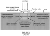
- Figure 1 illustrates how the introduction of compressive stress into a material works when using laser peening, keeping in mind that the concept of plastic compression and transverse expansion is common to all treatments.
- Laser peening is a particularly important post processing method for metal parts. Laser peening is now extensively used to enhance the fatigue lifetime of jet engine fan and compressor blades, and more recently in aircraft structures, and even in spent nuclear fuel storage canisters. It has also been applied to improve surface properties in additively manufactured Maraging steel. Laser peening technology is also used to apply curvature and stretch to thick sections of aircraft wing panels, thus providing precise aerodynamic shaping. In the LP process, short intensive laser pulses create a plasma in a confined geometry, which is shown as area "A" in Figure 1 . This results in pressure pulses that create local plastic deformation.
- An ablative layer can be used in the process or, as in this work, such a layer may be omitted, resulting in only a very shallow (10 to 20 ⁇ m thick) layer of recast material that can be left on the surface or easily polished off.
- Use of a water tamper "B" increases the generating pressure by an order of magnitude thus making the process more efficient.
- modifications to stress state and/or shape can be precisely generated in parts in a spot-by-spot manner using the LP method.
- Laser peened materials typically demonstrate higher cracking and corrosion resistance and are becoming widely used in manufacturing.
- Laser peening is also known for creating very small amounts of cold work, typically 3% to 5%, typically leaving the phase, hardness, and yield strength of the treated material unchanged. Shot peening typically requires multiple impacts estimated, for example, at 13 impacts for 100% coverage. Due to the spherical nature of the impacts, the shot generates transverse as well as normal forces and plastic deformation. This working of the surface increases hardness and generates cold work. While cold work isn't necessarily bad, physical ball peening has limited penetration depth and therefore efficiency compared to laser shock peening.
- US 2018/0001417 A1 discloses a method and an apparatus for use in laser shock peening.
- the apparatus may include a diode-pumped solid-state laser oscillator configured to output a pulsed laser beam, a modulator configured to modify an energy and a temporal profile of the pulsed laser beam, and an amplifier configured to amplify an energy of the pulse laser beam.
- US 2019/255649 A1 discloses a laser machining or cutting method that is carried out by a laser beam machine including a laser oscillator that is a first laser oscillator which emits a pulse of a laser beam that is a first laser beam, and a laser oscillator that is a second laser oscillator which emits a pulse of a laser beam that is a second laser beam differing in wavelength or pulse width from the first laser beam.
- the first laser beam and the second laser beam are caused to alternate in irradiating a workpiece.
- the present invention relates to a laser based system with the features of claim 1 for laser peening a workpiece.
- the present invention relates to a method with the features of claim 11 for laser shock peening a workpiece.
- a principal feature of the present disclosure is shaping of a laser-induced shock being applied to a material surface, through simultaneous spatio-temporal pulse shaping.
- a non-uniform input may be used that varies in time to allow a build-up or constructive accumulation of shock at a selected, specific point in the material.
- the phase of the pulse preferably scales across the laser beam such that different components of the laser pulse arrive at the surface at different times.
- the system 10 may include one or more lasers 12 (e.g., pulse laser) and a controller 14 for controlling On/Off operation of the laser(s) 12. While the use of two or more lasers is contemplated, for convenience, the following discussion will focus on the system using a single pulse laser 12.
- the controller 14 may be formed by a computer or any other suitable type of processing component which is able to control On/Off operation of the laser 12 with the necessary degree of control to create a series of carefully timed pulses.
- the controller 14 may include a non-volatile memory 16 (e.g., RAM, ROM, etc.) for storing any data/parameters needed for operation of the system 10.
- the controller 14 may also communicate with a spatio-temporal beam shaping system/software module 18 (hereinafter simply “beam shaping module” 18) for controlling the shape (i.e., fluence) of laser energy applied by each pulse of the laser 12 to a workpiece 20 by a beam 12a of the laser 12.
- beam shaping module 18 a spatio-temporal beam shaping system/software module 18 for controlling the shape (i.e., fluence) of laser energy applied by each pulse of the laser 12 to a workpiece 20 by a beam 12a of the laser 12.
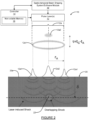
- Figure 2 shows the use of two distinct beam components 12a1 and 12a2 to more easily help the reader visualize how the spatio-temporal beam shaping applied by the system 10 operates.
- one beam component 12a1 of the beam 12 consists of an annular or 'donut' shaped beam that arrives at time t A .
- the other beam component 12a2 is a standard Gaussian profile beam that arrives at a later time t G , but still while the beam 12a1 is being applied to the workpiece 20.
- the radial position of the annular beam component 12a1 may be given by r A and the laser-induced shock velocity caused by beam component12a1 can be given by vs.
- the graph 100 illustrates a single laser pulse 102 in which the laser fluence is modified throughout the pulse length, and simultaneously spatially over the cross-sectional area of the beam, to achieve the same (or closely similar) result as that described above in connection with the distinct first and second beam pulse components 102a1 and 102a2.
- the overall length of the pulse 102 (comprising both beam pulse components 102a1 and 102a2) may be in the millisecond range, the microsecond range or the nanosecond range, or possibly even shorter.
- the single pulse 102 is initially created to apply a laser fluence, indicated by first beam pulse component102a1, to generate a first shock wave in the workpiece 20.
- This laser fluence creating the first beam pulse component 102a1 is applied for a first time duration 104, which in this example represents only a fractional portion of the overall duration of the single pulse 102. It will be understood, however, that the first beam pulse component 102a1 may be applied during the full time of the pulse 102 or any other fractional portion thereof, depending the needs of a particular application.
- the pulse 102 begins to apply the second beam pulse component 102a2, which in this example has a Gaussian profile beam fluence.
- the first beam pulse component 102a1 and the second beam pulse component102a2 are being applied simultaneously.
- the first beam pulse component 102a1 and the second beam pulse component 102a2 may be applied such that they are separated in time, such as indicated by dashed Gaussian beam spot 103.
- beam pulse components 102a1 and 102a2 may be annular and Gaussian profile beams, respectively, virtually any other beam pattern shapes (e.g., square, elliptical, etc.) are readily implementable using the system 10, with suitable modifications to the beam shaping module 18 and/or its software.
- the shocks created by the beam pulse components 102a1 and 102a2 created in the workpiece 20 propagate toward one another and overlap at a precise X-Y location within the workpiece, and at a precisely controlled depth below the upper surface 20a of the workpiece 20.
- any number of pulses can be imposed with similar synchronization to achieve optimized processing conditions.
- a continuously varying 'composite' pulse can be contemplated in which the spatio-temporal shaping of a single pulse allows for portions of it to arrive at different locations within the workpiece 20 at different times.
- One possible method to achieve this would be to spatially 'chirp' the laser pulse and send it through dispersive elements that delay different spatial components.
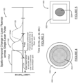
- Figure 4 shows a laser beam 200 in accordance with another construction in which an outer annular beam component 202 is created, which is partially overlapped by an inner Gaussian profile beam spot 204 (shown in shading) centered within the outer annular beam component.
- Figure 5 shows still another example of a beam construction 300 which may be implemented using the system 10.
- an outer, square, annular beam component 302 is created, and a separate Gaussian profile beam spot component 304 is centered within the outer, annular beam component 302.
- the beam components may be generated to overlap in time or such that they do not overlap in time. These are but a few variations of the shapes that the beam components may take.
- a particular advantage of the system 10 and method of the present invention is that laser peening with, for example, a square or rectangular beam, as used here in one embodiment of the system, in contrast generates 100% coverage in only one impact per beam spot (i.e., one impact of the beam 12a).
- the impact angle which is determined by the plasma pressure on the surface 20a of the workpiece 20 material being acted on and not the laser light incident angle, is totally normal to the surface 20a, thus generating little hardening or cold work.
- the large footprint of the laser beam 12a typically 3 mm to 10 mm on a side, and the steady nature of the shock, result in a very deep (multiple mm) plastic deformation of the material of the workpiece 20 before the shock drops below the yielding limit.
- different embodiments of the system 10 may include multiple, synchronized pulses from a single laser or from multiple lasers. Furthermore, because processing may take place at some distance and through dispersive media (e.g., water in laser shock peening or air for long stand-off material processing), the laser system may include additional dispersion compensating elements to account for this.
- dispersive media e.g., water in laser shock peening or air for long stand-off material processing
Landscapes
- Physics & Mathematics (AREA)
- Optics & Photonics (AREA)
- Engineering & Computer Science (AREA)
- Plasma & Fusion (AREA)
- Mechanical Engineering (AREA)
- Laser Beam Processing (AREA)
- Lasers (AREA)
Description
- The present disclosure relates to pulsed laser material processing systems and methods, more particularly to a laser based system and a method for laser peening a workpiece, see claims 1 and 11, which generates spatio-temporal varying pulses during a laser shock peening operation, to even more effectively create compressive stresses deep below a surface of a workpiece.
- The statements in this section merely provide background information related to the present disclosure and may not constitute prior art.
- Pulsed laser processing of materials has been used in a variety of applications from micro-machining, engraving, 3D printing and laser shock peening. In all applications, the generation of extreme temperatures and pressures at a specific location allows materials to be processed in ways that are generally not available to continuous wave (CW) lasers. For example, laser shock peening is a process that plastically compresses material normal to a surface, resulting in transverse (Poisson) expansion. A thicker or otherwise constrained component's ability to resist the transverse straining results in a local buildup of compressive stress. For thinner components, the peening results in strain and shape change. Such is the case for all types of compressive surface treatments including shot, laser, and ultrasonic peening and processes such as deep cold rolling.
Figure 1 illustrates how the introduction of compressive stress into a material works when using laser peening, keeping in mind that the concept of plastic compression and transverse expansion is common to all treatments. - Laser peening (LP) is a particularly important post processing method for metal parts. Laser peening is now extensively used to enhance the fatigue lifetime of jet engine fan and compressor blades, and more recently in aircraft structures, and even in spent nuclear fuel storage canisters. It has also been applied to improve surface properties in additively manufactured Maraging steel. Laser peening technology is also used to apply curvature and stretch to thick sections of aircraft wing panels, thus providing precise aerodynamic shaping. In the LP process, short intensive laser pulses create a plasma in a confined geometry, which is shown as area "A" in
Figure 1 . This results in pressure pulses that create local plastic deformation. An ablative layer can be used in the process or, as in this work, such a layer may be omitted, resulting in only a very shallow (10 to 20 µm thick) layer of recast material that can be left on the surface or easily polished off. Use of a water tamper "B" increases the generating pressure by an order of magnitude thus making the process more efficient. Depending on variables such as material and geometry, existing residual compressive stresses, desired strains or desired microstructure, modifications to stress state and/or shape can be precisely generated in parts in a spot-by-spot manner using the LP method. Laser peened materials typically demonstrate higher cracking and corrosion resistance and are becoming widely used in manufacturing. - Laser peening is also known for creating very small amounts of cold work, typically 3% to 5%, typically leaving the phase, hardness, and yield strength of the treated material unchanged. Shot peening typically requires multiple impacts estimated, for example, at 13 impacts for 100% coverage. Due to the spherical nature of the impacts, the shot generates transverse as well as normal forces and plastic deformation. This working of the surface increases hardness and generates cold work. While cold work isn't necessarily bad, physical ball peening has limited penetration depth and therefore efficiency compared to laser shock peening.
-
US 2018/0001417 A1 (describing the features and steps of the preamble of claims 1 and 11) discloses a method and an apparatus for use in laser shock peening. The apparatus may include a diode-pumped solid-state laser oscillator configured to output a pulsed laser beam, a modulator configured to modify an energy and a temporal profile of the pulsed laser beam, and an amplifier configured to amplify an energy of the pulse laser beam. -
US 2019/255649 A1 discloses a laser machining or cutting method that is carried out by a laser beam machine including a laser oscillator that is a first laser oscillator which emits a pulse of a laser beam that is a first laser beam, and a laser oscillator that is a second laser oscillator which emits a pulse of a laser beam that is a second laser beam differing in wavelength or pulse width from the first laser beam. In the laser beam machining method, the first laser beam and the second laser beam are caused to alternate in irradiating a workpiece. - This section provides a general summary of the present invention, and is not a comprehensive disclosure of its full scope or all of its features.
- In one aspect the present invention relates to a laser based system with the features of claim 1 for laser peening a workpiece.
- In another aspect the present invention relates to a method with the features of claim 11 for laser shock peening a workpiece.
- Further preferred embodiments of the present invention are defined in the dependent claims.
- Further areas of applicability will become apparent from the description provided herein. It should be understood that the description and specific examples are intended for purposes of illustration only and are not intended to limit the scope of the present disclosure.
- The drawings described herein are for illustrative purposes only of selected embodiments and not all possible implementations, and are not intended to limit the scope of the present disclosure.
- Corresponding reference numerals indicate corresponding parts throughout the several views of the drawings.
-
Figure 1 is a prior art illustration showing how laser shock peening plastically deforms material generating an internal compressive stress field; and -
Figure 2 is a high level diagrammatic illustration showing how a spatio-temporal laser pulse is used to create a controlled, overlapping shock region, for enhanced laser shock peening. -
Figure 3 is a graph further illustrating how the two pulse components described in connection with the system shown inFigure 2 are created to overlap in time, or alternatively to not overlap in time, to create two distinct shock waves that propagate to and overlap at a predetermined location and depth within the workpiece; -
Figure 4 is a plan view of another beam construction of the present disclosure which uses an annular outer beam component with a partially overlapping Gaussian profile beam spot, which is arranged concentrically with the outer annular beam component; and -
Figure 5 is still another example of a beam construction of the present disclosure in which a square shaped, annular, outer beam component is used with an elliptically shaped, Gaussian profile beam component, which is also arrange concentrically within the square shaped, annular outer beam component. - Example embodiments will now be described more fully with reference to the accompanying drawings.
- A principal feature of the present disclosure is shaping of a laser-induced shock being applied to a material surface, through simultaneous spatio-temporal pulse shaping. In contrast to the conditions shown in
Figure 1 , a non-uniform input may be used that varies in time to allow a build-up or constructive accumulation of shock at a selected, specific point in the material. Similar to a lens, the phase of the pulse preferably scales across the laser beam such that different components of the laser pulse arrive at the surface at different times. - Referring to
Figure 2 , asystem 10 in accordance with one embodiment of the present invention is shown. Thesystem 10 may include one or more lasers 12 (e.g., pulse laser) and acontroller 14 for controlling On/Off operation of the laser(s) 12. While the use of two or more lasers is contemplated, for convenience, the following discussion will focus on the system using asingle pulse laser 12. Thecontroller 14 may be formed by a computer or any other suitable type of processing component which is able to control On/Off operation of thelaser 12 with the necessary degree of control to create a series of carefully timed pulses. Thecontroller 14 may include a non-volatile memory 16 (e.g., RAM, ROM, etc.) for storing any data/parameters needed for operation of thesystem 10. Thecontroller 14 may also communicate with a spatio-temporal beam shaping system/software module 18 (hereinafter simply "beam shaping module" 18) for controlling the shape (i.e., fluence) of laser energy applied by each pulse of thelaser 12 to aworkpiece 20 by abeam 12a of thelaser 12. - While it is anticipated that the use of a single, spatio-temporally generated pulse, applied repeatedly, will likely be a preferable implementation of the
system 10,Figure 2 shows the use of two distinct beam components 12a1 and 12a2 to more easily help the reader visualize how the spatio-temporal beam shaping applied by thesystem 10 operates. In this example one beam component 12a1 of thebeam 12 consists of an annular or 'donut' shaped beam that arrives at time tA. The other beam component 12a2 is a standard Gaussian profile beam that arrives at a later time tG, but still while the beam 12a1 is being applied to theworkpiece 20. If the relative delay between the start of the two beam components 12a1 and 12a2 is τ= tG - tA, the radial position of the annular beam component 12a1 may be given by rA and the laser-induced shock velocity caused by beam component12a1 can be given by vs. The shock from the two pulses 12a1 and 12a2 will coincide at depth δ (denoted by reference number 22) below anupper surface 20a of the workpiece. This produces an enhancement of shock in the material of theworkpiece 20 for τ = (δlvG ) (√1 + r2 /δ2 A - 1). - One skilled in the art will recognize multiple optical configurations that will lead to such an enhancement, so long as individual components of the
beam 12a arrive at the same desired location at the same time, given the above equation. This is also illustrated ingraph 100 ofFigure 3 . Thegraph 100 illustrates asingle laser pulse 102 in which the laser fluence is modified throughout the pulse length, and simultaneously spatially over the cross-sectional area of the beam, to achieve the same (or closely similar) result as that described above in connection with the distinct first and second beam pulse components 102a1 and 102a2. The overall length of the pulse 102 (comprising both beam pulse components 102a1 and 102a2) may be in the millisecond range, the microsecond range or the nanosecond range, or possibly even shorter. In this example thesingle pulse 102 is initially created to apply a laser fluence, indicated by first beam pulse component102a1, to generate a first shock wave in theworkpiece 20. This laser fluence creating the first beam pulse component 102a1 is applied for afirst time duration 104, which in this example represents only a fractional portion of the overall duration of thesingle pulse 102. It will be understood, however, that the first beam pulse component 102a1 may be applied during the full time of thepulse 102 or any other fractional portion thereof, depending the needs of a particular application. Then in this example, while the laser fluence creating the first beam pulse component 102a1 is still being applied to theworkpiece 20, thepulse 102 begins to apply the second beam pulse component 102a2, which in this example has a Gaussian profile beam fluence. As such, in this example the first beam pulse component 102a1 and the second beam pulse component102a2 are being applied simultaneously. Alternatively, the first beam pulse component 102a1 and the second beam pulse component 102a2 may be applied such that they are separated in time, such as indicated by dashedGaussian beam spot 103. Still further, more than two distinct beam pulse components may be applied, where all overlap one another, or only certain portions of the beam portions overlap one another, or none of the beam portions overlap one another, and all of these variations are contemplated by the present disclosure. And while the beam pulse components 102a1 and 102a2 may be annular and Gaussian profile beams, respectively, virtually any other beam pattern shapes (e.g., square, elliptical, etc.) are readily implementable using thesystem 10, with suitable modifications to thebeam shaping module 18 and/or its software. In either instance, the shocks created by the beam pulse components 102a1 and 102a2 created in theworkpiece 20 propagate toward one another and overlap at a precise X-Y location within the workpiece, and at a precisely controlled depth below theupper surface 20a of theworkpiece 20. Furthermore, any number of pulses can be imposed with similar synchronization to achieve optimized processing conditions. Indeed, a continuously varying 'composite' pulse can be contemplated in which the spatio-temporal shaping of a single pulse allows for portions of it to arrive at different locations within theworkpiece 20 at different times. One possible method to achieve this would be to spatially 'chirp' the laser pulse and send it through dispersive elements that delay different spatial components. -
Figure 4 shows alaser beam 200 in accordance with another construction in which an outerannular beam component 202 is created, which is partially overlapped by an inner Gaussian profile beam spot 204 (shown in shading) centered within the outer annular beam component.Figure 5 shows still another example of abeam construction 300 which may be implemented using thesystem 10. In this example an outer, square,annular beam component 302 is created, and a separate Gaussian profilebeam spot component 304 is centered within the outer,annular beam component 302. In thebeams material workpiece 20. - A particular advantage of the
system 10 and method of the present invention is that laser peening with, for example, a square or rectangular beam, as used here in one embodiment of the system, in contrast generates 100% coverage in only one impact per beam spot (i.e., one impact of thebeam 12a). The impact angle, which is determined by the plasma pressure on thesurface 20a of theworkpiece 20 material being acted on and not the laser light incident angle, is totally normal to thesurface 20a, thus generating little hardening or cold work. Additionally, the large footprint of thelaser beam 12a, typically 3 mm to 10 mm on a side, and the steady nature of the shock, result in a very deep (multiple mm) plastic deformation of the material of theworkpiece 20 before the shock drops below the yielding limit. Previously published work in this area has compared cold work generated by shot, gravity and laser peening as inferred from the measured angular dispersion in x-ray diffraction. The deep, strong shock produced by thesystem 10 inserts dislocations equally deep into materials which helps resist crack initiation and growth, thereby supporting enhancement in fatigue strength and increasing the lifetime of treated components. Thesystem 10 creates especially deep compressive stresses which resist the advance of cracks, as well as providing superior resistance to stress corrosion cracking in susceptible materials. By selectively and compressively prestressing high tensile stress areas of components, the laser peening performed using thesystem 10 also enables even higher levels of tensile fatigue loading before the fatigue limit of a material is reached. - It should also be noted that different embodiments of the
system 10 may include multiple, synchronized pulses from a single laser or from multiple lasers. Furthermore, because processing may take place at some distance and through dispersive media (e.g., water in laser shock peening or air for long stand-off material processing), the laser system may include additional dispersion compensating elements to account for this. - The foregoing description of the embodiments has been provided for purposes of illustration and description. It is not intended to be exhaustive or to limit the present invention. Individual elements or features of a particular embodiment are generally not limited to that particular embodiment, but, where applicable, are interchangeable and can be used in a selected embodiment, even if not specifically shown or described. The same may also be varied in many ways. Such variations are not to be regarded as a departure from the present invention, and all such modifications are intended to be included within the scope of the present invention as defined in the appended claims.
Claims (14)
- A laser based system (10) for laser peening a workpiece (20), the system (10) comprising:a pulse laser (12) configured to generate laser pulses;a controller (14) for controlling operation of the pulse laser (12); and characterised by:the controller (14) being configured to control the pulse laser (12) to cause the pulse laser (12) to generate at least one of the laser pulses with a spatio-temporally varying laser fluence over a duration of the at least one of the laser pulses;wherein the spatio-temporally varying laser fluence produces first and second beam components (12a1; 102a1; 12a2; 102a2) of the at least one of the laser pulses which arrive at a surface (20a) of the workpiece (20) at different times; andwherein the first and second beam components (12a1; 102a1; 12a2;102a2) are timed to create an overlapping shock at a desired location below the surface (20a) of the workpiece (20).
- The system (10) of claim 1, wherein the first and second beam components (102a1;102a2) are generated to overlap one another in time.
- The system (10) of claim 1, wherein one of the first and second beam components (12a1;102a1;12a2;102a2) comprises an annular shaped beam component.
- The system (10) of claim 1, wherein one of the first and second beam components (12a1;102a1;12a2;102a2) comprises a Gaussian profile shaped beam component.
- The system (10) of claim 1, wherein one of the first and second beam components comprises at least one of a circular spot, an elliptical spot or an annular square shape.
- The system (10) of claim 5, wherein the at least one of the circular spot or the elliptical spot further comprises a laser fluence having a Gaussian profile.
- The system (10) of claim 1, wherein the first and second beam components (12a1;12a2) are formed such that they do not overlap spatially when impinging the surface (20a) of the workpiece (20).
- The system (10) of claim 1, wherein the first and second beam components (102a1;102a2) are formed such that they overlap spatially when impinging the surface (20a) of the workpiece (20).
- The system (10) of claim 1, wherein the first and second beam components of the at least one laser pulse are timed to propagate towards, and to arrive at, the same location within an interior area of the workpiece (20) at the same time.
- The system (10) of claim 1, wherein the first one of the first and second beam components (12a1;12a2) comprises an annular or shaped beam that arrives at time tA, and the second one of the first and second beam components (12a1;12a2) comprises a standard Gaussian profile beam that arrives at a later time tG, but while the first beam component (12a1) is still being applied to the workpiece (20), and wherein a relative delay between a start of the first and second beam components (12a1;12a2) is defined as:
 wherein a radial position of the first beam component (12a1) is given by ra,wherein a laser-induced shock velocity caused by the first beam component (12a1) can be given by vs;wherein shocks from the first and second beam components (12a1;12a2) coincide at depth δ below the surface (20a) of the workpiece (20);and wherein an enhancement of shock in the material of the workpiece (20) for τ is represented by (δlvG ) (√1 + r2 /δ2 A - 1).
 - A method for laser peening a workpiece (20), the method comprising:generating a plurality of laser pulses directed at a surface (20a) of the workpiece (20);the method being characterised by the following:for at least one of said laser pulses, further controlling the generation of the pulse to have a spatio-temporally varying laser fluence over a duration of the laser pulse that creates first and second beam components (12a1;102a1;12a2;102a2) of the laser pulse which arrive at the surface (20a) of the workpiece (20) at different times; andthe first and second beam components (12a1;102a1;12a2;102a2) propagating into the workpiece (20) to a location below the surface (20a) of the workpiece (20),wherein the first and second beam components (12a1;102a1;12a2;102a2) are timed to create an overlapping shock within the workpiece (20) at a desired location below the surface (20a) of the workpiece (20).
- The method of claim 11, wherein the first beam component (102a1) is applied before the second beam component (102a2).
- The method of claim 11, wherein the second beam component (102a2) is applied while the first beam component (102a1) is still being generated, such that the first and second beam components (102a1;102a2) overlap one another in time.
- The method of claim 11, wherein creation of the first and second beam components comprises:creating one of the first and second beam components (102a1;102a2) with an annular beam shape; andcreating the other one of the first and second beam components (102a1; 102a2) as a spot having a Gaussian profile beam fluence.
Applications Claiming Priority (2)
| Application Number | Priority Date | Filing Date | Title |
|---|---|---|---|
| US16/580,141 US11638970B2 (en) | 2019-09-24 | 2019-09-24 | Enhanced material shock using spatiotemporal laser pulse formatting |
| PCT/US2020/051977 WO2021133444A2 (en) | 2019-09-24 | 2020-09-22 | Enhanced material shock using spatiotemporal laser pulse formatting |
Publications (3)
| Publication Number | Publication Date |
|---|---|
| EP4034331A2 EP4034331A2 (en) | 2022-08-03 |
| EP4034331A4 EP4034331A4 (en) | 2023-08-09 |
| EP4034331B1 true EP4034331B1 (en) | 2024-11-06 |
Family
ID=74880445
Family Applications (1)
| Application Number | Title | Priority Date | Filing Date |
|---|---|---|---|
| EP20908373.2A Active EP4034331B1 (en) | 2019-09-24 | 2020-09-22 | System and method for laser peening a workpiece |
Country Status (3)
| Country | Link |
|---|---|
| US (1) | US11638970B2 (en) |
| EP (1) | EP4034331B1 (en) |
| WO (1) | WO2021133444A2 (en) |
Families Citing this family (5)
| Publication number | Priority date | Publication date | Assignee | Title |
|---|---|---|---|---|
| CN114406475B (en) * | 2021-12-01 | 2023-09-22 | 江苏大学 | A method for preparing aluminum alloy superhydrophobic surface by laser shot peening |
| CN115870623B (en) * | 2022-11-29 | 2025-10-03 | 江苏大学 | A deep cooling laser shock device and method |
| US20240335907A1 (en) * | 2022-11-29 | 2024-10-10 | Jiangsu University | Cryogenic laser shock device and method |
| CN117286317A (en) * | 2023-10-30 | 2023-12-26 | 西北工业大学 | A method of strengthening austenitic stainless steel |
| CN118308589B (en) * | 2024-06-11 | 2024-09-06 | 中南大学 | A composite forming method and device of electric pulse creep aging and laser shot peening |
Family Cites Families (9)
| Publication number | Priority date | Publication date | Assignee | Title |
|---|---|---|---|---|
| US6198069B1 (en) | 1998-08-13 | 2001-03-06 | The Regents Of The University Of California | Laser beam temporal and spatial tailoring for laser shock processing |
| US6752593B2 (en) * | 2001-08-01 | 2004-06-22 | Lsp Technologies, Inc. | Articles having improved residual stress profile characteristics produced by laser shock peening |
| US6670577B2 (en) | 2001-09-28 | 2003-12-30 | General Electric Company | Laser shock peening method and apparatus |
| US7750266B2 (en) | 2004-11-17 | 2010-07-06 | Metal Improvement Company Llc | Active beam delivery system for laser peening and laser peening method |
| DE102013217783A1 (en) | 2013-09-05 | 2015-03-05 | Sauer Gmbh Lasertec | Method for processing a workpiece by means of a laser beam, laser tool, laser machine, machine control |
| US9744618B2 (en) * | 2014-05-22 | 2017-08-29 | Lsp Technologies, Inc. | Temporal pulse shaping for laser shock peening |
| EP3242768B8 (en) | 2015-01-09 | 2019-10-23 | LSP Technologies, Inc. | Method and apparatus for use in laser shock peening processes |
| US11273521B2 (en) | 2016-04-11 | 2022-03-15 | Lsp Technologies, Inc. | Method and apparatus for laser shock peening ballistic armor |
| US20190255649A1 (en) | 2017-09-26 | 2019-08-22 | Mitsubishi Electric Corporation | Laser beam machining method and laser beam machine |
-
2019
- 2019-09-24 US US16/580,141 patent/US11638970B2/en active Active
-
2020
- 2020-09-22 WO PCT/US2020/051977 patent/WO2021133444A2/en not_active Ceased
- 2020-09-22 EP EP20908373.2A patent/EP4034331B1/en active Active
Also Published As
| Publication number | Publication date |
|---|---|
| US11638970B2 (en) | 2023-05-02 |
| WO2021133444A3 (en) | 2021-09-10 |
| EP4034331A2 (en) | 2022-08-03 |
| US20210086302A1 (en) | 2021-03-25 |
| EP4034331A4 (en) | 2023-08-09 |
| WO2021133444A2 (en) | 2021-07-01 |
Similar Documents
| Publication | Publication Date | Title |
|---|---|---|
| EP4034331B1 (en) | System and method for laser peening a workpiece | |
| RU2228234C2 (en) | Process for shaping metals by means of laser forging | |
| CN100582255C (en) | Method for modifying or producing materials and joints by generating and applying adaptive pulses, normalized energy and pauses therebetween | |
| EP3229994B1 (en) | Additive manufacturing and integrated impact post-treatment | |
| US20040086738A1 (en) | Laser peening of components of thin cross-section | |
| Clauer | Laser shock peening for fatigue resistance | |
| US6993948B2 (en) | Methods for altering residual stresses using mechanically induced liquid cavitation | |
| EP2986410B1 (en) | Process diagnostic system for and method of performing laser shock peening on a target with a fluid flow path sandwiched beteen a transparent to laser light solid medium and the target | |
| US20040224179A1 (en) | Laser peening method and apparatus using tailored laser beam spot sizes | |
| EP1483418B1 (en) | Pre-loading of components during laser peenforming | |
| EP3845333B1 (en) | Metal additive manufacturing method | |
| US20230219294A1 (en) | Hybrid additive manufacturing method | |
| US5671628A (en) | Laser shock peened dies | |
| KR20140132411A (en) | Method and device for the fracture separation of a workpiece | |
| US7832614B2 (en) | Method of explosion welding to create an explosion welded article having a non-planar shape | |
| US9115417B2 (en) | Liquid drop peening method and apparatus therefor | |
| EP3995668A1 (en) | A method for extending fatigue life of a turbine blade affected by pitting and product thereof | |
| EP2855719B1 (en) | Deep laser peening | |
| RU2762308C1 (en) | Method for heat treatment of a section of a steel billet and a steel billet obtained by this method | |
| US20250128328A1 (en) | An integrated system and method for in-situ laser peening of a three-dimensional printed part | |
| Tessmann et al. | Bidirectional Bending of Thin Metals With Femtosecond Lasers |
Legal Events
| Date | Code | Title | Description |
|---|---|---|---|
| STAA | Information on the status of an ep patent application or granted ep patent |
Free format text: STATUS: THE INTERNATIONAL PUBLICATION HAS BEEN MADE |
|
| PUAI | Public reference made under article 153(3) epc to a published international application that has entered the european phase |
Free format text: ORIGINAL CODE: 0009012 |
|
| STAA | Information on the status of an ep patent application or granted ep patent |
Free format text: STATUS: REQUEST FOR EXAMINATION WAS MADE |
|
| 17P | Request for examination filed |
Effective date: 20220211 |
|
| AK | Designated contracting states |
Kind code of ref document: A2 Designated state(s): AL AT BE BG CH CY CZ DE DK EE ES FI FR GB GR HR HU IE IS IT LI LT LU LV MC MK MT NL NO PL PT RO RS SE SI SK SM TR |
|
| RIN1 | Information on inventor provided before grant (corrected) |
Inventor name: MATTHEWS, MANYALIBO JOSEPH |
|
| DAV | Request for validation of the european patent (deleted) | ||
| DAX | Request for extension of the european patent (deleted) | ||
| P01 | Opt-out of the competence of the unified patent court (upc) registered |
Effective date: 20230526 |
|
| A4 | Supplementary search report drawn up and despatched |
Effective date: 20230710 |
|
| RIC1 | Information provided on ipc code assigned before grant |
Ipc: C21D 10/00 20060101ALI20230704BHEP Ipc: B23K 26/06 20140101ALI20230704BHEP Ipc: B23K 26/0622 20140101ALI20230704BHEP Ipc: B23K 26/073 20060101ALI20230704BHEP Ipc: B23K 26/356 20140101AFI20230704BHEP |
|
| GRAP | Despatch of communication of intention to grant a patent |
Free format text: ORIGINAL CODE: EPIDOSNIGR1 |
|
| STAA | Information on the status of an ep patent application or granted ep patent |
Free format text: STATUS: GRANT OF PATENT IS INTENDED |
|
| RIC1 | Information provided on ipc code assigned before grant |
Ipc: C21D 10/00 20060101ALI20240510BHEP Ipc: B23K 26/06 20140101ALI20240510BHEP Ipc: B23K 26/0622 20140101ALI20240510BHEP Ipc: B23K 26/073 20060101ALI20240510BHEP Ipc: B23K 26/356 20140101AFI20240510BHEP |
|
| INTG | Intention to grant announced |
Effective date: 20240529 |
|
| GRAS | Grant fee paid |
Free format text: ORIGINAL CODE: EPIDOSNIGR3 |
|
| GRAA | (expected) grant |
Free format text: ORIGINAL CODE: 0009210 |
|
| STAA | Information on the status of an ep patent application or granted ep patent |
Free format text: STATUS: THE PATENT HAS BEEN GRANTED |
|
| AK | Designated contracting states |
Kind code of ref document: B1 Designated state(s): AL AT BE BG CH CY CZ DE DK EE ES FI FR GB GR HR HU IE IS IT LI LT LU LV MC MK MT NL NO PL PT RO RS SE SI SK SM TR |
|
| REG | Reference to a national code |
Ref country code: GB Ref legal event code: FG4D |
|
| REG | Reference to a national code |
Ref country code: CH Ref legal event code: EP |
|
| REG | Reference to a national code |
Ref country code: DE Ref legal event code: R096 Ref document number: 602020041092 Country of ref document: DE |
|
| REG | Reference to a national code |
Ref country code: IE Ref legal event code: FG4D |
|
| REG | Reference to a national code |
Ref country code: LT Ref legal event code: MG9D |
|
| REG | Reference to a national code |
Ref country code: NL Ref legal event code: MP Effective date: 20241106 |
|
| PG25 | Lapsed in a contracting state [announced via postgrant information from national office to epo] |
Ref country code: PT Free format text: LAPSE BECAUSE OF FAILURE TO SUBMIT A TRANSLATION OF THE DESCRIPTION OR TO PAY THE FEE WITHIN THE PRESCRIBED TIME-LIMIT Effective date: 20250306 Ref country code: IS Free format text: LAPSE BECAUSE OF FAILURE TO SUBMIT A TRANSLATION OF THE DESCRIPTION OR TO PAY THE FEE WITHIN THE PRESCRIBED TIME-LIMIT Effective date: 20250306 Ref country code: HR Free format text: LAPSE BECAUSE OF FAILURE TO SUBMIT A TRANSLATION OF THE DESCRIPTION OR TO PAY THE FEE WITHIN THE PRESCRIBED TIME-LIMIT Effective date: 20241106 |
|
| PG25 | Lapsed in a contracting state [announced via postgrant information from national office to epo] |
Ref country code: FI Free format text: LAPSE BECAUSE OF FAILURE TO SUBMIT A TRANSLATION OF THE DESCRIPTION OR TO PAY THE FEE WITHIN THE PRESCRIBED TIME-LIMIT Effective date: 20241106 Ref country code: NL Free format text: LAPSE BECAUSE OF FAILURE TO SUBMIT A TRANSLATION OF THE DESCRIPTION OR TO PAY THE FEE WITHIN THE PRESCRIBED TIME-LIMIT Effective date: 20241106 |
|
| REG | Reference to a national code |
Ref country code: AT Ref legal event code: MK05 Ref document number: 1738845 Country of ref document: AT Kind code of ref document: T Effective date: 20241106 |
|
| PG25 | Lapsed in a contracting state [announced via postgrant information from national office to epo] |
Ref country code: BG Free format text: LAPSE BECAUSE OF FAILURE TO SUBMIT A TRANSLATION OF THE DESCRIPTION OR TO PAY THE FEE WITHIN THE PRESCRIBED TIME-LIMIT Effective date: 20241106 |
|
| PG25 | Lapsed in a contracting state [announced via postgrant information from national office to epo] |
Ref country code: ES Free format text: LAPSE BECAUSE OF FAILURE TO SUBMIT A TRANSLATION OF THE DESCRIPTION OR TO PAY THE FEE WITHIN THE PRESCRIBED TIME-LIMIT Effective date: 20241106 |
|
| PG25 | Lapsed in a contracting state [announced via postgrant information from national office to epo] |
Ref country code: NO Free format text: LAPSE BECAUSE OF FAILURE TO SUBMIT A TRANSLATION OF THE DESCRIPTION OR TO PAY THE FEE WITHIN THE PRESCRIBED TIME-LIMIT Effective date: 20250206 |
|
| PG25 | Lapsed in a contracting state [announced via postgrant information from national office to epo] |
Ref country code: GR Free format text: LAPSE BECAUSE OF FAILURE TO SUBMIT A TRANSLATION OF THE DESCRIPTION OR TO PAY THE FEE WITHIN THE PRESCRIBED TIME-LIMIT Effective date: 20250207 Ref country code: LV Free format text: LAPSE BECAUSE OF FAILURE TO SUBMIT A TRANSLATION OF THE DESCRIPTION OR TO PAY THE FEE WITHIN THE PRESCRIBED TIME-LIMIT Effective date: 20241106 Ref country code: AT Free format text: LAPSE BECAUSE OF FAILURE TO SUBMIT A TRANSLATION OF THE DESCRIPTION OR TO PAY THE FEE WITHIN THE PRESCRIBED TIME-LIMIT Effective date: 20241106 |
|
| PG25 | Lapsed in a contracting state [announced via postgrant information from national office to epo] |
Ref country code: PL Free format text: LAPSE BECAUSE OF FAILURE TO SUBMIT A TRANSLATION OF THE DESCRIPTION OR TO PAY THE FEE WITHIN THE PRESCRIBED TIME-LIMIT Effective date: 20241106 |
|
| PG25 | Lapsed in a contracting state [announced via postgrant information from national office to epo] |
Ref country code: RS Free format text: LAPSE BECAUSE OF FAILURE TO SUBMIT A TRANSLATION OF THE DESCRIPTION OR TO PAY THE FEE WITHIN THE PRESCRIBED TIME-LIMIT Effective date: 20250206 |
|
| PG25 | Lapsed in a contracting state [announced via postgrant information from national office to epo] |
Ref country code: SM Free format text: LAPSE BECAUSE OF FAILURE TO SUBMIT A TRANSLATION OF THE DESCRIPTION OR TO PAY THE FEE WITHIN THE PRESCRIBED TIME-LIMIT Effective date: 20241106 |
|
| PG25 | Lapsed in a contracting state [announced via postgrant information from national office to epo] |
Ref country code: DK Free format text: LAPSE BECAUSE OF FAILURE TO SUBMIT A TRANSLATION OF THE DESCRIPTION OR TO PAY THE FEE WITHIN THE PRESCRIBED TIME-LIMIT Effective date: 20241106 |
|
| PG25 | Lapsed in a contracting state [announced via postgrant information from national office to epo] |
Ref country code: EE Free format text: LAPSE BECAUSE OF FAILURE TO SUBMIT A TRANSLATION OF THE DESCRIPTION OR TO PAY THE FEE WITHIN THE PRESCRIBED TIME-LIMIT Effective date: 20241106 |
|
| PG25 | Lapsed in a contracting state [announced via postgrant information from national office to epo] |
Ref country code: RO Free format text: LAPSE BECAUSE OF FAILURE TO SUBMIT A TRANSLATION OF THE DESCRIPTION OR TO PAY THE FEE WITHIN THE PRESCRIBED TIME-LIMIT Effective date: 20241106 |
|
| PG25 | Lapsed in a contracting state [announced via postgrant information from national office to epo] |
Ref country code: SK Free format text: LAPSE BECAUSE OF FAILURE TO SUBMIT A TRANSLATION OF THE DESCRIPTION OR TO PAY THE FEE WITHIN THE PRESCRIBED TIME-LIMIT Effective date: 20241106 |
|
| PG25 | Lapsed in a contracting state [announced via postgrant information from national office to epo] |
Ref country code: CZ Free format text: LAPSE BECAUSE OF FAILURE TO SUBMIT A TRANSLATION OF THE DESCRIPTION OR TO PAY THE FEE WITHIN THE PRESCRIBED TIME-LIMIT Effective date: 20241106 |
|
| PG25 | Lapsed in a contracting state [announced via postgrant information from national office to epo] |
Ref country code: IT Free format text: LAPSE BECAUSE OF FAILURE TO SUBMIT A TRANSLATION OF THE DESCRIPTION OR TO PAY THE FEE WITHIN THE PRESCRIBED TIME-LIMIT Effective date: 20241106 |
|
| REG | Reference to a national code |
Ref country code: DE Ref legal event code: R097 Ref document number: 602020041092 Country of ref document: DE |
|
| PG25 | Lapsed in a contracting state [announced via postgrant information from national office to epo] |
Ref country code: SE Free format text: LAPSE BECAUSE OF FAILURE TO SUBMIT A TRANSLATION OF THE DESCRIPTION OR TO PAY THE FEE WITHIN THE PRESCRIBED TIME-LIMIT Effective date: 20241106 |
|
| PLBE | No opposition filed within time limit |
Free format text: ORIGINAL CODE: 0009261 |
|
| STAA | Information on the status of an ep patent application or granted ep patent |
Free format text: STATUS: NO OPPOSITION FILED WITHIN TIME LIMIT |
|
| 26N | No opposition filed |
Effective date: 20250807 |