EP1627841A1 - Antrieb für eine Aufzugsanlage - Google Patents
Antrieb für eine Aufzugsanlage Download PDFInfo
- Publication number
- EP1627841A1 EP1627841A1 EP05104913A EP05104913A EP1627841A1 EP 1627841 A1 EP1627841 A1 EP 1627841A1 EP 05104913 A EP05104913 A EP 05104913A EP 05104913 A EP05104913 A EP 05104913A EP 1627841 A1 EP1627841 A1 EP 1627841A1
- Authority
- EP
- European Patent Office
- Prior art keywords
- brake
- drive
- motor
- support
- housing
- Prior art date
- Legal status (The legal status is an assumption and is not a legal conclusion. Google has not performed a legal analysis and makes no representation as to the accuracy of the status listed.)
- Granted
Links
Images


Classifications
-
- B—PERFORMING OPERATIONS; TRANSPORTING
- B66—HOISTING; LIFTING; HAULING
- B66B—ELEVATORS; ESCALATORS OR MOVING WALKWAYS
- B66B11/00—Main component parts of lifts in, or associated with, buildings or other structures
- B66B11/04—Driving gear ; Details thereof, e.g. seals
- B66B11/043—Driving gear ; Details thereof, e.g. seals actuated by rotating motor; Details, e.g. ventilation
Definitions
- the invention relates to a drive for an elevator installation according to the preamble of the independent claim.
- An elevator system consists of a cabin for receiving cargo or persons and a counterweight, or a second cabin, which are connected to each other by means of a support and propellant means of a drive.
- the drive of the elevator system aims to drive the driving and suspension means and thus a reciprocal lifting and lowering of the car and counterweight.
- the drive consists of the main components traction sheave, motor and brake.
- the traction sheave receives the carrying and blowing agent and transmits by means of positive or frictional connection driving forces on the carrying and blowing agents.
- the engine in turn drives the traction sheave and the brake brakes the traction sheave.
- Motor, brake and traction sheave are accordingly connected to each other in terms of force and torque.
- a drive to an elevator in which a motor drives traction sheaves by means of a drive shaft and the traction sheaves are braked by a brake.
- the traction sheaves are arranged, in a preferred embodiment, between the engine and the brake unit.
- the traction sheaves drive flat belts. This allows the use of small pulley diameters.
- the drive can be made small and compact. The small dimensions and compact design of this drive result in new challenges. Brake and motor housings must be connected to each other in terms of force and torque. The connection to the brake must be safety-compliant, ie at least form-fitting. The small dimensions should be maintained.
- the object of the present invention is to provide a drive to an elevator installation, which has small external dimensions, is designed in accordance with safety and can be produced inexpensively.
- the invention relates to a drive for an elevator system, which drives a car and a counterweight via a support and propellant and the drive includes a traction sheave, which is driven by a drive shaft of a motor and braked by a brake, wherein drive shaft, motor and brake assembled with a support to a unit.
- the support forms the common support structure of the drive to which, depending on the embodiment, parts of the drive are arranged. It allows the attachment of the drive in the building.
- the support can be an integral part of the engine or the brake or it can be a housing which receives, for example bearings of the drive or surrounds the traction sheaves.
- the brake is connected by means of pins with the housing of the motor or with the support or with another brake. That is, the torque transfer from the brake to the support or the housing of the engine or to a next brake by means of pins.
- a pin bore while the housing of the motor or the support, and the brake, or a fixed part of the brake, a pin bore.
- the pin is inserted in the pin bore of the motor, or the support.
- the brake is secured by means of the brake-side pin bore on the corresponding pin.
- the brake is thus torque-resistant, or positively connected to the engine or the support.
- the pins and the connection points at brake and housing, or support are easy to produce. As a result, a cost-effective and space-saving connection of the brake in the drive is possible, which also meets the safety requirements, which are placed on a positive connection.
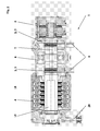
- Fig. 1 shows a drive for an elevator installation with the main characteristic of the invention.
- the drive 1 has one or more drive pulley zones 3 and a drive pulley zone 3 comprises at least one traction sheave 2.
- the traction sheave 2 serves to receive a carrying and driving means 6 which connects a car of the elevator with a counterweight or a second car.
- the traction sheave 2 is integrated in the drive 1 shown in a drive shaft 7.
- a motor 4, which drives the drive shaft 7, is subsequently arranged on the traction sheave 2.
- a brake 5 or a fixed part of the brake is connected to a support 8 by means of bolts, pins or pins 11.
- the attachment of the brake 5 takes place taking into account the space conditions and an optimal power flow either to a housing 12 of the motor 4, as shown in Fig. 3 or to the support 8, as shown in FIGS. 1 and 2.
- the use of pin 11 forms a cost-effective and space-saving design for mounting the brake fifth
- the pin 11 is inserted at one end into a mating pin hole 30 of the support 8 or the housing 12, or the end of the pin 11 is in the support 8, or in the housing 12, sunk.
- the pin 11 defines a predetermined distance between the brake 5 and the support 8, and the housing 12.
- a brake disc 22 and a brake pressure plate 23 are arranged.
- the brake disk 22 is non-positively connected to the motor shaft 15 or the drive shaft 7 and rotates with the rotational speed of the motor 4.
- the brake pressure plate 23 is attracted in the operating position of the drive 1 to the housing of the brake 5, for example.
- the pins 11 and the connection points in the brake 5 and the housing 12 of the motor 4, or support 8 are in the whole considered easy to manufacture. As a result, a cost-effective and space-saving attachment of the brake 5 in the drive 1 is possible, which also meets the safety requirements, which are placed on a positive mounting the brake to the engine.
- a two-circuit brake can be executed, which can also be used for safety-related functions.
- the drive 1 consists in a preferred embodiment of two spaced apart blowing zones 3, wherein a blowing zone 3, one or more traction sheaves 2 may include.
- the motor 4 and / or the brake 5 are arranged outside the two blowing zones 3, and a main bearing 25 is arranged between the two blowing zones 3, so that a main supporting force of, generated by the support and drive belt 6, carrying capacity, essentially, means the main bearing 25 is introduced into a support structure.
- the drive can be made compact and inexpensive.
- the belts are flat according to the design of the traction sheave 2, that is smooth, or they have a longitudinal profiling, for example in the form of V-ribs or they have a transverse profile, for example a tooth shape.
- motor shaft 15, drive shaft 7 and traction sheave 2 are made in one piece.
- motor shaft 15 and the drive shaft 7 may be made in one piece, or the drive shaft 7 and the traction sheave 2 are made in one piece.
- the production as individual separate parts is of course possible.
- the choice of suitable embodiment is made at the choice of the manufacturer.
- the brake 5 can also be arranged on the motor-side end of the drive shaft, for example, outside the support 28.
Landscapes
- Engineering & Computer Science (AREA)
- Civil Engineering (AREA)
- Mechanical Engineering (AREA)
- Structural Engineering (AREA)
- Cage And Drive Apparatuses For Elevators (AREA)
Abstract
Description
- Die Erfindung betrifft einen Antrieb für eine Aufzugsanlage gemäss Oberbegriff des unabhängigen Patentanspruches.
- Eine Aufzugsanlage besteht aus einer Kabine zur Aufnahme von Transportgut oder Personen und einem Gegengewicht, bzw. einer zweiten Kabine, welche mittels einem Trag- und Treibmittel über einen Antrieb miteinander verbunden sind. Der Antrieb der Aufzugsanlage bezweckt dabei das Treiben der Treib- und Tragmittel und damit ein wechselseitiges Heben und Senken von Kabine und Gegengewicht.
- Der Antrieb besteht aus den Hauptkomponenten Treibscheibe, Motor und Bremse. Die Treibscheibe nimmt die Trag- und Treibmittel auf und überträgt mittels Form- oder Reibschluss Treibkräfte auf die Trag- und Treibmittel. Der Motor treibt seinerseits die Treibscheibe und die Bremse bremst die Treibscheibe.
Motor, Bremse und Treibscheibe sind dementsprechend Kräfte- und Momentenwirksam miteinander verbunden. - Aus EP 1'400'477 ist ein Antrieb zu einem Aufzug bekannt bei welchem ein Motor mittels einer Antriebswelle Treibscheiben treibt und die Treibscheiben von einer Bremse gebremst werden. Die Treibscheiben sind dabei, in einer bevorzugten Ausführungsform, zwischen dem Motor und der Bremseinheit angeordnet. Die Treibscheiben treiben Flachriemen. Dies erlaubt die Verwendung von kleinen Treibscheibendurchmessern. Der Antrieb kann dadurch klein und kompakt gebaut werden.
Die geringen Abmessungen und die kompakte Bauweise dieses Antriebes ergeben neue Herausforderungen. Brems- und Motorgehäuse müssen Kräfte- und Momentenwirksam miteinander verbunden sein. Die Verbindung zur Bremse muss sicherheitskonform, das heisst zumindest Formschlüssig ausgeführt sein. Dabei sollen die kleinen Abmessungen beibehalten werden. - Die Aufgabe der vorliegenden Erfindung ist es, einen Antrieb zu einer Aufzugsanlage bereitzustellen, welcher geringe äussere Abmessungen aufweist, sicherheitskonform ausgeführt ist und kostengünstig hergestellt werden kann.
- Diese Aufgabe wird durch die Merkmale des unabhängigen Patentanspruches gelöst.
- Die Erfindung betrifft einen Antrieb für eine Aufzugsanlage, welcher über ein Trag- und Treibmittel eine Kabine und ein Gegengewicht treibt und der Antrieb eine Treibscheibe beinhaltet, welche mittels einer Antriebswelle von einem Motor getrieben und von einer Bremse gebremst wird, wobei Antriebswelle, Motor und Bremse mit einem Support zu einer Einheit zusammengebaut sind. Der Support bildet die gemeinsame Tragstruktur des Antriebes an dem, je nach Ausführungsart, Teile des Antriebes angeordnet sind. Er ermöglicht die Befestigung des Antriebes im Gebäude. Der Support kann dabei ein integraler Bestandteil des Motors oder der Bremse sein oder er kann ein Gehäuse sein, welches beispielsweise Lagerstellen des Antriebs aufnimmt oder die Treibscheiben umschliesst.
- Erfindungsgemäss ist die Bremse mittels Zapfen mit dem Gehäuse des Motors oder mit dem Support oder mit einer weiteren Bremse verbunden. D.h. die Momentenübertragung von der Bremse zum Support oder zum Gehäuse des Motors oder zu einer nächsten Bremse erfolgt mittels Zapfen. Vorteilhafterweise enthalten dabei das Gehäuse des Motors oder der Support, und die Bremse, bzw. ein feststehender Teil der Bremse, eine Zapfenbohrung. Der Zapfen ist in die Zapfenbohrung des Motors, bzw. des Supports eingefügt. Die Bremse ist mittels der bremsseitigen Zapfenbohrung auf den entsprechenden Zapfen befestigt. Die Bremse ist damit Drehmomentenfest, bzw. Formschlüssig mit dem Motor bzw. dem Support verbunden.
Die Zapfen sowie die Anschlussstellen bei Bremse und Gehäuse, bzw. Support sind einfach herstellbar. Dadurch ist eine kostengünstige und platzsparende Verbindung der Bremse im Antrieb möglich, welche zudem die Sicherheitsanforderungen erfüllt, welche an eine formschlüssige Verbindung gestellt werden. - In den folgenden Figuren Fig. 1 bis Fig. 3 sind vorteilhafte Ausführungen der Erfindung beispielhaft dargestellt.
- Fig. 1:
- Beispiel eines ausgeführten erfindungsgemässen Antriebes
- Fig. 2:
- ein weiteres Beispiel eines erfindungsgemässen Antriebes
- Fig. 3:
- Beispiel einer Bremsbefestigung mittels Zapfen
- Fig. 1 zeigt einen Antrieb für eine Aufzugsanlage mit der Hauptcharakteristik der Erfindung. Der Antrieb 1 weist eine oder mehrere Treibscheibenzonen 3 auf und eine Treibscheibenzone 3 umfasst mindestens eine Treibscheibe 2. Die Treibscheibe 2 dient der Aufnahme eines Trag- und Treibmittels 6 welches eine Kabine des Aufzuges mit einem Gegengewicht bzw. einer zweiten Kabine verbindet.
Die Treibscheibe 2 ist beim gezeigten Antrieb 1 in eine Antriebswelle 7 integriert. Ein Motor 4, welcher die Antriebswelle 7 antreibt, ist anschliessend an die Treibscheibe 2 angeordnet. - Erfindungsgemäss ist eine Bremse 5, bzw. ein feststehender Teil der Bremse, wie in Fig. 1, 2 und 3 dargestellt, mittels Bolzen, Stift oder Zapfen 11 mit einem Support 8 verbunden. Die Befestigung der Bremse 5 erfolgt dabei unter Berücksichtigung der Platzverhältnisse und eines optimalen Kraftflusses wahlweise an ein Gehäuse 12 des Motors 4, wie in Fig. 3 dargestellt oder an den Support 8, wie in den Fig. 1 und 2 dargestellt. Die Verwendung von Zapfen 11 bildet eine kostengünstige und platzsparende Ausführung zur Befestigung der Bremse 5.
- Vorteilhafterweise ist der Zapfen 11 an dessen einem Ende in eine passende Zapfenbohrung 30 des Supports 8 oder des Gehäuses 12 gesteckt, bzw. das Ende des Zapfens 11 ist im Support 8, bzw. im Gehäuse 12, versenkt angeordnet. Auf ein gegenseitiges Ende des Zapfens 11 ist das Gehäuse der Bremse 5, bzw. ein feststehender Teil der Bremse 5, aufgesetzt. Der Zapfen 11 definiert eine vorbestimmte Distanz zwischen der Bremse 5 und dem Support 8, bzw. dem Gehäuse 12. Innerhalb der vorbestimmten Distanz sind eine Bremsscheibe 22 und eine Bremsdruckplatte 23 angeordnet. Die Bremsscheibe 22 ist kraftschlüssig mit der Motorwelle 15 oder der Antriebswelle 7 verbunden und dreht sich mit der Drehgeschwindigkeit des Motors 4. Die Bremsdruckplatte 23 ist in der Betriebsstellung des Antriebes 1 zum Gehäuse der Bremse 5 hingezogen, bspw. mittels eines Elektromagneten, und wird in der Bremsstellung freigeschalten, bzw. an die Bremsscheibe 22 gedrückt. Das Andrücken erfolgt in der Regel mittels Federn. Die Bremsscheibe 22 ist dadurch zwischen der Bremsdruckplatte 23 und einem Gegengehäuse, wie bspw. dem Support 8, dem Gehäuse 12 des Motors oder einer weiteren Bremse 5', festgeklemmt und bremst dadurch die Motorwelle 15 oder die Antriebswelle 7. Die Bremsdruckplatte 23 ist mittels des Zapfens 11 geführt, womit sie gegen Verdrehen gesichert ist. Zapfen 11 und Zapfenbohrungen 30 lassen sich kostengünstig herstellen. Der Antrieb kann dadurch kostengünstig hergestellt werden. Die dargestellte Ausführung beansprucht zudem wenig Platz.
In der Regel sind mehrere Zapfen 11 über den Umfang der Bremse 5 verteilt angebracht. Die Bremse 5 wird mittels Schrauben, welche vorzugsweise durch eine Längsbohrung 24 des Zapfens 11 geführt sind, befestigt. - Die Zapfen 11 sowie die Anschlussstellen bei der Bremse 5 und Gehäuse 12 des Motors 4, bzw. Support 8 sind im gesamten betrachtet einfach herstellbar. Dadurch ist ein kostengünstiger und Platz sparender Anbau der Bremse 5 im Antrieb 1 möglich, welcher zudem die Sicherheitsanforderungen, welche an einen formschlüssigen Anbau der Bremse an den Motor gestellt werden, erfüllt.
- In einer besonders sicheren Ausführung sind zwei Bremsmodule 5',5" wie in Fig. 1 und Fig. 2 dargestellt zu einer Bremse 5 zusammengeschalten.
Dadurch ist eine Zwei-Kreis-Bremse ausführbar, welche auch für sicherheitsrelevante Funktionen eingesetzt werden kann. - Wie in den Fig. 1 und 2 dargestellt besteht der Antrieb 1 in einer bevorzugten Ausführung aus zwei voneinander beabstandeten Treibzonen 3, wobei eine Treibzone 3, ein oder mehrere Treibscheiben 2 beinhalten kann. Der Motor 4 und /oder die Bremse 5 sind ausserhalb der beiden Treibzonen 3 angeordnet, und ein Hauptlager 25 ist zwischen den beiden Treibzonen 3 angeordnet, so dass eine Hauptstützkraft der, durch die Trag- und Treibriemen 6 erzeugten, Tragkraft, im wesentlichen, mittels dem Hauptlager 25 in eine Tragstruktur eingeleitet wird.
Damit ist eine direkte und optimale Einleitung der Tragkräfte des Antriebes 1 in eine Tragstruktur ermöglicht. Der Antrieb kann dadurch kompakt gebaut und kostengünstig ausgeführt werden. - Besonders vorteilhaft ist die Verwendung von Riemen als Trag- und Treibmittel 6. Trag- und Treibriemen 6 erlauben die Verwendung von kleinen Treibscheibendurchmessern. Dadurch kann ein Antrieb 1 mit entsprechend hohen Drehzahlen und geringen Drehmomenten verwendet werden, was wiederum den Einsatz von Antrieben mit geringen Abmessungen und die Verwendung marktüblicher und entsprechend kostengünstiger Bremsen erlaubt.
- Die Riemen sind dabei entsprechend der Ausführung der Treibscheibe 2 flach, das heisst glatt, oder sie weisen eine Längsprofilierung, beispielsweise in der Form von Keilrippen auf oder sie weisen ein Querprofil, beispielsweise eine Zahnform auf.
- In den gezeigten Beispielen der Fig. 1 und Fig. 2 sind Motorwelle 15, Antriebswelle 7 und Treibscheibe 2 einstückig ausgeführt. Alternativ können lediglich die Motorwelle 15 und die Antriebswelle 7 einstückig ausgeführt sein, oder die Antriebswelle 7 und die Treibscheibe 2 sind aus einem Stück hergestellt. Auch die Herstellung als einzelne separate Teile ist selbstverständlich möglich. Die Wahl der geeigneten Ausführungsform erfolgt nach Wahl des Herstellers.
- Die Einleitung einer Stützkraft mittels einer Motorseitig angebrachten Stütze 28 entlastet im dargestellten Beispiel die Bremse 5 von Stützkräften. Die Zapfen 11, bzw. der Bremsanbau wird dadurch nur durch die bremseigenen Kräfte - Bremsmoment und Anpresskraft - belastet.
- Die dargestellten Ausführungsformen und Verfahren sind Beispiele. So kann beispielsweise die Bremse 5 auch am motorseitigen Ende der Antriebswelle, beispielsweise ausserhalb der Stütze 28, angeordnet sein.
Claims (7)
- Antrieb für eine Aufzugsanlage
welcher über Trag- und Treibmittel (6) eine Kabine und ein Gegengewicht treibt, wobei der Antrieb (1) eine Antriebswelle (7) und eine Treibscheibe (2) beinhaltet und eine Bremse (5) links oder rechts der Treibscheibe (2) oder an einem Ende eines Motors angeordnet ist,
dadurch gekennzeichnet,
dass die Momentenübertragung von der Bremse (5) zum Support (8) oder zum Gehäuse (12) des Motors (4) oder zu einer nächsten Bremse (5') mittels Zapfen (11) erfolgt. - Antrieb nach Anspruch 1 dadurch gekennzeichnet, dass
der Zapfen (11) einen Abstand zwischen dem Gehäuse der Bremse (5) und einem Support (8) oder Gehäuse (12) des Motors (4) oder einer weiteren Bremse (5') definiert und ein Ende des Zapfens (11) an einem Ende in der Bremse (5) versenkt angeordnet ist und ein anderes Ende des Zapfens (11) im Support (8) oder Gehäuse (12) des Motors (4) oder in einer weiteren Bremse (5') versenkt angeordnet ist. - Antrieb nach einem der vorgängigen Patentansprüche dadurch gekennzeichnet, dass
der Zapfen (11) eine Längsbohrung (24) aufweist und die Bremse (5) durch die Längsbohrung (24) mit dem Support (8) oder Gehäuse (12) des Motors (4) oder mit einer weiteren Bremse (5') verbunden ist. - Antrieb nach einem der vorgängigen Patentansprüche dadurch gekennzeichnet, dass
zwei oder mehrere Bremsen (5', 5'') zu einer Bremse (5) zusammengefügt sind. - Antrieb nach einem der vorgängigen Patentansprüche
dadurch gekennzeichnet, dass
der Antrieb (1) mindestens zwei voneinander beabstandete Treibzonen (3) mit jeweils mindestens einer Treibscheibe (2) enthält und ein dass ein Hauptlager (25) zwischen den Treibzonen (3) angeordnet ist und dass ein Motor (4) und /oder eine Bremse (5) ausserhalb der beiden Treibzonen (3) angeordnet ist. - Antrieb nach einem der vorgängigen Patentansprüche
dadurch gekennzeichnet, dass
das Trag- und Treibmittel (6) ein Riemen ist, wobei die Traktionsfläche flach, längsprofiliert oder querprofiliert ist. - Antrieb nach einem der vorgängigen Patentansprüche
dadurch gekennzeichnet, dass
Motorwelle (15) und Antriebswelle (7) einstückig ausgeführt ist und / oder dass die Treibscheiben (2) und die Antriebswelle (7) einstückig ausgeführt ist.
Priority Applications (1)
| Application Number | Priority Date | Filing Date | Title |
|---|---|---|---|
| EP20050104913 EP1627841B1 (de) | 2004-06-19 | 2005-06-06 | Antrieb für eine Aufzugsanlage |
Applications Claiming Priority (2)
| Application Number | Priority Date | Filing Date | Title |
|---|---|---|---|
| EP04014438 | 2004-06-19 | ||
| EP20050104913 EP1627841B1 (de) | 2004-06-19 | 2005-06-06 | Antrieb für eine Aufzugsanlage |
Publications (2)
| Publication Number | Publication Date |
|---|---|
| EP1627841A1 true EP1627841A1 (de) | 2006-02-22 |
| EP1627841B1 EP1627841B1 (de) | 2013-08-28 |
Family
ID=35722276
Family Applications (1)
| Application Number | Title | Priority Date | Filing Date |
|---|---|---|---|
| EP20050104913 Expired - Lifetime EP1627841B1 (de) | 2004-06-19 | 2005-06-06 | Antrieb für eine Aufzugsanlage |
Country Status (1)
| Country | Link |
|---|---|
| EP (1) | EP1627841B1 (de) |
Families Citing this family (1)
| Publication number | Priority date | Publication date | Assignee | Title |
|---|---|---|---|---|
| WO2011099123A1 (ja) | 2010-02-10 | 2011-08-18 | 三菱電機株式会社 | エレベータ用巻上機のブレーキ装置 |
Citations (3)
| Publication number | Priority date | Publication date | Assignee | Title |
|---|---|---|---|---|
| US5631510A (en) * | 1993-11-05 | 1997-05-20 | Mannesmann Aktiengesellschaft | Electric drive with brakes, in particular for hoists, lifting devices or positioning transporting systems |
| DE19737485C1 (de) * | 1997-08-28 | 1999-06-17 | Stromag Ag | Elektromagnetisch betätigbare Bremse und Mehrfachbremsaggregat |
| EP1400477A2 (de) * | 2002-09-05 | 2004-03-24 | Inventio Ag | Anordnung von Antriebsmaschine einer Aufzuganlage |
-
2005
- 2005-06-06 EP EP20050104913 patent/EP1627841B1/de not_active Expired - Lifetime
Patent Citations (3)
| Publication number | Priority date | Publication date | Assignee | Title |
|---|---|---|---|---|
| US5631510A (en) * | 1993-11-05 | 1997-05-20 | Mannesmann Aktiengesellschaft | Electric drive with brakes, in particular for hoists, lifting devices or positioning transporting systems |
| DE19737485C1 (de) * | 1997-08-28 | 1999-06-17 | Stromag Ag | Elektromagnetisch betätigbare Bremse und Mehrfachbremsaggregat |
| EP1400477A2 (de) * | 2002-09-05 | 2004-03-24 | Inventio Ag | Anordnung von Antriebsmaschine einer Aufzuganlage |
Also Published As
| Publication number | Publication date |
|---|---|
| EP1627841B1 (de) | 2013-08-28 |
Similar Documents
| Publication | Publication Date | Title |
|---|---|---|
| EP1621509B1 (de) | Anordnung von einer Antriebsmaschine einer Aufzugsanlage | |
| EP0917518A1 (de) | Treibscheibenaufzug | |
| EP0706968B1 (de) | Antriebseinheit für ein Hebezeug | |
| EP1470013A1 (de) | Direkt angetriebene antriebsachse mit zwei antriebsmotoren | |
| DE112015004418T5 (de) | Elektrische Feststellbremse mit zwei unabhängigen Aktuatoren | |
| EP0834463A1 (de) | Kompakt-Antrieb für Aufzüge | |
| EP2147884B1 (de) | Hebevorrichtung, insbesondere Aufzug oder Hebebühne | |
| DE3922274C2 (de) | ||
| EP1627841B1 (de) | Antrieb für eine Aufzugsanlage | |
| DE10260003A1 (de) | Radnabenantrieb | |
| EP4265556B1 (de) | Antriebsmaschine für einen aufzug | |
| EP2089305B1 (de) | Antrieb für aufzüge | |
| DE10136031B4 (de) | Direktantrieb für eine Personenförderanlage | |
| EP1555236B1 (de) | Antrieb für eine Aufzugsanlage und Verfahren zum Umbau eines Antriebes in einer Aufzugsanlage | |
| EP1607361B1 (de) | Antrieb mit Signalgeber für eine Aufzugsanlage | |
| DE20000913U1 (de) | Getriebehebewerk | |
| EP1431233B1 (de) | Hydraulischer Seilantrieb für Aufzüge | |
| DE202004005300U1 (de) | Aufzugsantriebseinheit | |
| DE19828213A1 (de) | Hebezeugantrieb | |
| DE102024102307A1 (de) | Welle mit drehfest verbundenen unterschiedlich großen Wellenabschnitten | |
| EP4711316A1 (de) | Antrieb für einen aufzug, aufzug umfassend einen antrieb sowie verfahren zum nachrüsten eines seilaufzugs mit einem antrieb | |
| DE102016108349A1 (de) | Hebevorrichtung, insbesondere Aufzug oder Hebebühne | |
| EP1795432A1 (de) | Antrieb für Flurförderfahrzeuge | |
| DE3205980A1 (de) | Elektromagnetische haltebremse | |
| DE102009048089A1 (de) | Seilbremse für ein Aufzugsystem |
Legal Events
| Date | Code | Title | Description |
|---|---|---|---|
| PUAI | Public reference made under article 153(3) epc to a published international application that has entered the european phase |
Free format text: ORIGINAL CODE: 0009012 |
|
| AK | Designated contracting states |
Kind code of ref document: A1 Designated state(s): AT BE BG CH CY CZ DE DK EE ES FI FR GB GR HU IE IS IT LI LT LU MC NL PL PT RO SE SI SK TR |
|
| AX | Request for extension of the european patent |
Extension state: AL BA HR LV MK YU |
|
| 17P | Request for examination filed |
Effective date: 20060821 |
|
| AKX | Designation fees paid |
Designated state(s): AT BE BG CH CY CZ DE DK EE ES FI FR GB GR HU IE IS IT LI LT LU MC NL PL PT RO SE SI SK TR |
|
| REG | Reference to a national code |
Ref country code: HK Ref legal event code: DE Ref document number: 1088879 Country of ref document: HK |
|
| 17Q | First examination report despatched |
Effective date: 20130125 |
|
| GRAP | Despatch of communication of intention to grant a patent |
Free format text: ORIGINAL CODE: EPIDOSNIGR1 |
|
| GRAS | Grant fee paid |
Free format text: ORIGINAL CODE: EPIDOSNIGR3 |
|
| INTG | Intention to grant announced |
Effective date: 20130620 |
|
| GRAA | (expected) grant |
Free format text: ORIGINAL CODE: 0009210 |
|
| AK | Designated contracting states |
Kind code of ref document: B1 Designated state(s): AT BE BG CH CY CZ DE DK EE ES FI FR GB GR HU IE IS IT LI LT LU MC NL PL PT RO SE SI SK TR |
|
| REG | Reference to a national code |
Ref country code: GB Ref legal event code: FG4D Free format text: NOT ENGLISH |
|
| REG | Reference to a national code |
Ref country code: CH Ref legal event code: EP |
|
| REG | Reference to a national code |
Ref country code: AT Ref legal event code: REF Ref document number: 629219 Country of ref document: AT Kind code of ref document: T Effective date: 20130915 |
|
| REG | Reference to a national code |
Ref country code: IE Ref legal event code: FG4D Free format text: LANGUAGE OF EP DOCUMENT: GERMAN |
|
| REG | Reference to a national code |
Ref country code: DE Ref legal event code: R096 Ref document number: 502005013938 Country of ref document: DE Effective date: 20131017 |
|
| REG | Reference to a national code |
Ref country code: LT Ref legal event code: MG4D |
|
| REG | Reference to a national code |
Ref country code: NL Ref legal event code: VDEP Effective date: 20130828 |
|
| PG25 | Lapsed in a contracting state [announced via postgrant information from national office to epo] |
Ref country code: PT Free format text: LAPSE BECAUSE OF FAILURE TO SUBMIT A TRANSLATION OF THE DESCRIPTION OR TO PAY THE FEE WITHIN THE PRESCRIBED TIME-LIMIT Effective date: 20131230 Ref country code: CY Free format text: LAPSE BECAUSE OF FAILURE TO SUBMIT A TRANSLATION OF THE DESCRIPTION OR TO PAY THE FEE WITHIN THE PRESCRIBED TIME-LIMIT Effective date: 20130710 Ref country code: IS Free format text: LAPSE BECAUSE OF FAILURE TO SUBMIT A TRANSLATION OF THE DESCRIPTION OR TO PAY THE FEE WITHIN THE PRESCRIBED TIME-LIMIT Effective date: 20131228 Ref country code: SE Free format text: LAPSE BECAUSE OF FAILURE TO SUBMIT A TRANSLATION OF THE DESCRIPTION OR TO PAY THE FEE WITHIN THE PRESCRIBED TIME-LIMIT Effective date: 20130828 Ref country code: LT Free format text: LAPSE BECAUSE OF FAILURE TO SUBMIT A TRANSLATION OF THE DESCRIPTION OR TO PAY THE FEE WITHIN THE PRESCRIBED TIME-LIMIT Effective date: 20130828 |
|
| REG | Reference to a national code |
Ref country code: NL Ref legal event code: VDEP Effective date: 20130828 |
|
| PG25 | Lapsed in a contracting state [announced via postgrant information from national office to epo] |
Ref country code: GR Free format text: LAPSE BECAUSE OF FAILURE TO SUBMIT A TRANSLATION OF THE DESCRIPTION OR TO PAY THE FEE WITHIN THE PRESCRIBED TIME-LIMIT Effective date: 20131129 Ref country code: PL Free format text: LAPSE BECAUSE OF FAILURE TO SUBMIT A TRANSLATION OF THE DESCRIPTION OR TO PAY THE FEE WITHIN THE PRESCRIBED TIME-LIMIT Effective date: 20130828 Ref country code: FI Free format text: LAPSE BECAUSE OF FAILURE TO SUBMIT A TRANSLATION OF THE DESCRIPTION OR TO PAY THE FEE WITHIN THE PRESCRIBED TIME-LIMIT Effective date: 20130828 Ref country code: SI Free format text: LAPSE BECAUSE OF FAILURE TO SUBMIT A TRANSLATION OF THE DESCRIPTION OR TO PAY THE FEE WITHIN THE PRESCRIBED TIME-LIMIT Effective date: 20130828 |
|
| REG | Reference to a national code |
Ref country code: HK Ref legal event code: GR Ref document number: 1088879 Country of ref document: HK |
|
| PG25 | Lapsed in a contracting state [announced via postgrant information from national office to epo] |
Ref country code: CY Free format text: LAPSE BECAUSE OF FAILURE TO SUBMIT A TRANSLATION OF THE DESCRIPTION OR TO PAY THE FEE WITHIN THE PRESCRIBED TIME-LIMIT Effective date: 20130828 |
|
| PG25 | Lapsed in a contracting state [announced via postgrant information from national office to epo] |
Ref country code: SK Free format text: LAPSE BECAUSE OF FAILURE TO SUBMIT A TRANSLATION OF THE DESCRIPTION OR TO PAY THE FEE WITHIN THE PRESCRIBED TIME-LIMIT Effective date: 20130828 Ref country code: DK Free format text: LAPSE BECAUSE OF FAILURE TO SUBMIT A TRANSLATION OF THE DESCRIPTION OR TO PAY THE FEE WITHIN THE PRESCRIBED TIME-LIMIT Effective date: 20130828 Ref country code: RO Free format text: LAPSE BECAUSE OF FAILURE TO SUBMIT A TRANSLATION OF THE DESCRIPTION OR TO PAY THE FEE WITHIN THE PRESCRIBED TIME-LIMIT Effective date: 20130828 Ref country code: EE Free format text: LAPSE BECAUSE OF FAILURE TO SUBMIT A TRANSLATION OF THE DESCRIPTION OR TO PAY THE FEE WITHIN THE PRESCRIBED TIME-LIMIT Effective date: 20130828 Ref country code: NL Free format text: LAPSE BECAUSE OF FAILURE TO SUBMIT A TRANSLATION OF THE DESCRIPTION OR TO PAY THE FEE WITHIN THE PRESCRIBED TIME-LIMIT Effective date: 20130828 Ref country code: CZ Free format text: LAPSE BECAUSE OF FAILURE TO SUBMIT A TRANSLATION OF THE DESCRIPTION OR TO PAY THE FEE WITHIN THE PRESCRIBED TIME-LIMIT Effective date: 20130828 |
|
| PG25 | Lapsed in a contracting state [announced via postgrant information from national office to epo] |
Ref country code: ES Free format text: LAPSE BECAUSE OF FAILURE TO SUBMIT A TRANSLATION OF THE DESCRIPTION OR TO PAY THE FEE WITHIN THE PRESCRIBED TIME-LIMIT Effective date: 20130828 |
|
| REG | Reference to a national code |
Ref country code: DE Ref legal event code: R097 Ref document number: 502005013938 Country of ref document: DE |
|
| PLBE | No opposition filed within time limit |
Free format text: ORIGINAL CODE: 0009261 |
|
| STAA | Information on the status of an ep patent application or granted ep patent |
Free format text: STATUS: NO OPPOSITION FILED WITHIN TIME LIMIT |
|
| 26N | No opposition filed |
Effective date: 20140530 |
|
| REG | Reference to a national code |
Ref country code: DE Ref legal event code: R097 Ref document number: 502005013938 Country of ref document: DE Effective date: 20140530 |
|
| PG25 | Lapsed in a contracting state [announced via postgrant information from national office to epo] |
Ref country code: MC Free format text: LAPSE BECAUSE OF FAILURE TO SUBMIT A TRANSLATION OF THE DESCRIPTION OR TO PAY THE FEE WITHIN THE PRESCRIBED TIME-LIMIT Effective date: 20130828 Ref country code: LU Free format text: LAPSE BECAUSE OF FAILURE TO SUBMIT A TRANSLATION OF THE DESCRIPTION OR TO PAY THE FEE WITHIN THE PRESCRIBED TIME-LIMIT Effective date: 20140606 |
|
| REG | Reference to a national code |
Ref country code: IE Ref legal event code: MM4A |
|
| PG25 | Lapsed in a contracting state [announced via postgrant information from national office to epo] |
Ref country code: IE Free format text: LAPSE BECAUSE OF NON-PAYMENT OF DUE FEES Effective date: 20140606 |
|
| REG | Reference to a national code |
Ref country code: AT Ref legal event code: MM01 Ref document number: 629219 Country of ref document: AT Kind code of ref document: T Effective date: 20140606 |
|
| PG25 | Lapsed in a contracting state [announced via postgrant information from national office to epo] |
Ref country code: AT Free format text: LAPSE BECAUSE OF NON-PAYMENT OF DUE FEES Effective date: 20140606 |
|
| PG25 | Lapsed in a contracting state [announced via postgrant information from national office to epo] |
Ref country code: BG Free format text: LAPSE BECAUSE OF FAILURE TO SUBMIT A TRANSLATION OF THE DESCRIPTION OR TO PAY THE FEE WITHIN THE PRESCRIBED TIME-LIMIT Effective date: 20130828 |
|
| REG | Reference to a national code |
Ref country code: FR Ref legal event code: PLFP Year of fee payment: 12 |
|
| PG25 | Lapsed in a contracting state [announced via postgrant information from national office to epo] |
Ref country code: BE Free format text: LAPSE BECAUSE OF FAILURE TO SUBMIT A TRANSLATION OF THE DESCRIPTION OR TO PAY THE FEE WITHIN THE PRESCRIBED TIME-LIMIT Effective date: 20140630 Ref country code: TR Free format text: LAPSE BECAUSE OF FAILURE TO SUBMIT A TRANSLATION OF THE DESCRIPTION OR TO PAY THE FEE WITHIN THE PRESCRIBED TIME-LIMIT Effective date: 20130828 Ref country code: HU Free format text: LAPSE BECAUSE OF FAILURE TO SUBMIT A TRANSLATION OF THE DESCRIPTION OR TO PAY THE FEE WITHIN THE PRESCRIBED TIME-LIMIT; INVALID AB INITIO Effective date: 20050606 |
|
| REG | Reference to a national code |
Ref country code: FR Ref legal event code: PLFP Year of fee payment: 13 |
|
| REG | Reference to a national code |
Ref country code: FR Ref legal event code: PLFP Year of fee payment: 14 |
|
| PGFP | Annual fee paid to national office [announced via postgrant information from national office to epo] |
Ref country code: IT Payment date: 20210622 Year of fee payment: 17 |
|
| REG | Reference to a national code |
Ref country code: DE Ref legal event code: R084 Ref document number: 502005013938 Country of ref document: DE |
|
| PG25 | Lapsed in a contracting state [announced via postgrant information from national office to epo] |
Ref country code: IT Free format text: LAPSE BECAUSE OF NON-PAYMENT OF DUE FEES Effective date: 20220606 |
|
| PGFP | Annual fee paid to national office [announced via postgrant information from national office to epo] |
Ref country code: GB Payment date: 20240619 Year of fee payment: 20 |
|
| PGFP | Annual fee paid to national office [announced via postgrant information from national office to epo] |
Ref country code: DE Payment date: 20240627 Year of fee payment: 20 |
|
| PGFP | Annual fee paid to national office [announced via postgrant information from national office to epo] |
Ref country code: FR Payment date: 20240625 Year of fee payment: 20 |
|
| PGFP | Annual fee paid to national office [announced via postgrant information from national office to epo] |
Ref country code: CH Payment date: 20240701 Year of fee payment: 20 |
|
| REG | Reference to a national code |
Ref country code: DE Ref legal event code: R071 Ref document number: 502005013938 Country of ref document: DE |
|
| REG | Reference to a national code |
Ref country code: CH Ref legal event code: PL |
|
| REG | Reference to a national code |
Ref country code: GB Ref legal event code: PE20 Expiry date: 20250605 |
|
| PG25 | Lapsed in a contracting state [announced via postgrant information from national office to epo] |
Ref country code: GB Free format text: LAPSE BECAUSE OF EXPIRATION OF PROTECTION Effective date: 20250605 |