EP1627756A1 - Anti-roll/nicksystem für ein Fahrzeug und Fahrzeug mit einem solchen System - Google Patents
Anti-roll/nicksystem für ein Fahrzeug und Fahrzeug mit einem solchen System Download PDFInfo
- Publication number
- EP1627756A1 EP1627756A1 EP04077360A EP04077360A EP1627756A1 EP 1627756 A1 EP1627756 A1 EP 1627756A1 EP 04077360 A EP04077360 A EP 04077360A EP 04077360 A EP04077360 A EP 04077360A EP 1627756 A1 EP1627756 A1 EP 1627756A1
- Authority
- EP
- European Patent Office
- Prior art keywords
- bearing arm
- vehicle
- vehicle mass
- spring
- arm
- Prior art date
- Legal status (The legal status is an assumption and is not a legal conclusion. Google has not performed a legal analysis and makes no representation as to the accuracy of the status listed.)
- Withdrawn
Links
Images


Classifications
-
- B—PERFORMING OPERATIONS; TRANSPORTING
- B60—VEHICLES IN GENERAL
- B60G—VEHICLE SUSPENSION ARRANGEMENTS
- B60G17/00—Resilient suspensions having means for adjusting the spring or vibration-damper characteristics, for regulating the distance between a supporting surface and a sprung part of vehicle or for locking suspension during use to meet varying vehicular or surface conditions, e.g. due to speed or load
- B60G17/02—Spring characteristics, e.g. mechanical springs and mechanical adjusting means
- B60G17/021—Spring characteristics, e.g. mechanical springs and mechanical adjusting means the mechanical spring being a coil spring
-
- B—PERFORMING OPERATIONS; TRANSPORTING
- B60—VEHICLES IN GENERAL
- B60G—VEHICLE SUSPENSION ARRANGEMENTS
- B60G11/00—Resilient suspensions characterised by arrangement, location or kind of springs
- B60G11/14—Resilient suspensions characterised by arrangement, location or kind of springs having helical, spiral or coil springs only
- B60G11/16—Resilient suspensions characterised by arrangement, location or kind of springs having helical, spiral or coil springs only characterised by means specially adapted for attaching the spring to axle or sprung part of the vehicle
-
- B—PERFORMING OPERATIONS; TRANSPORTING
- B60—VEHICLES IN GENERAL
- B60G—VEHICLE SUSPENSION ARRANGEMENTS
- B60G17/00—Resilient suspensions having means for adjusting the spring or vibration-damper characteristics, for regulating the distance between a supporting surface and a sprung part of vehicle or for locking suspension during use to meet varying vehicular or surface conditions, e.g. due to speed or load
- B60G17/02—Spring characteristics, e.g. mechanical springs and mechanical adjusting means
- B60G17/027—Mechanical springs regulated by fluid means
- B60G17/0272—Mechanical springs regulated by fluid means the mechanical spring being a coil spring
-
- B—PERFORMING OPERATIONS; TRANSPORTING
- B60—VEHICLES IN GENERAL
- B60G—VEHICLE SUSPENSION ARRANGEMENTS
- B60G3/00—Resilient suspensions for a single wheel
- B60G3/02—Resilient suspensions for a single wheel with a single pivoted arm
- B60G3/04—Resilient suspensions for a single wheel with a single pivoted arm the arm being essentially transverse to the longitudinal axis of the vehicle
- B60G3/06—Resilient suspensions for a single wheel with a single pivoted arm the arm being essentially transverse to the longitudinal axis of the vehicle the arm being rigid
-
- B—PERFORMING OPERATIONS; TRANSPORTING
- B60—VEHICLES IN GENERAL
- B60G—VEHICLE SUSPENSION ARRANGEMENTS
- B60G2200/00—Indexing codes relating to suspension types
- B60G2200/10—Independent suspensions
- B60G2200/14—Independent suspensions with lateral arms
- B60G2200/142—Independent suspensions with lateral arms with a single lateral arm, e.g. MacPherson type
-
- B—PERFORMING OPERATIONS; TRANSPORTING
- B60—VEHICLES IN GENERAL
- B60G—VEHICLE SUSPENSION ARRANGEMENTS
- B60G2200/00—Indexing codes relating to suspension types
- B60G2200/10—Independent suspensions
- B60G2200/17—Independent suspensions with a strut contributing to the suspension geometry by being articulated onto the wheel support
-
- B—PERFORMING OPERATIONS; TRANSPORTING
- B60—VEHICLES IN GENERAL
- B60G—VEHICLE SUSPENSION ARRANGEMENTS
- B60G2200/00—Indexing codes relating to suspension types
- B60G2200/10—Independent suspensions
- B60G2200/18—Multilink suspensions, e.g. elastokinematic arrangements
-
- B—PERFORMING OPERATIONS; TRANSPORTING
- B60—VEHICLES IN GENERAL
- B60G—VEHICLE SUSPENSION ARRANGEMENTS
- B60G2202/00—Indexing codes relating to the type of spring, damper or actuator
- B60G2202/10—Type of spring
- B60G2202/12—Wound spring
-
- B—PERFORMING OPERATIONS; TRANSPORTING
- B60—VEHICLES IN GENERAL
- B60G—VEHICLE SUSPENSION ARRANGEMENTS
- B60G2202/00—Indexing codes relating to the type of spring, damper or actuator
- B60G2202/40—Type of actuator
- B60G2202/42—Electric actuator
-
- B—PERFORMING OPERATIONS; TRANSPORTING
- B60—VEHICLES IN GENERAL
- B60G—VEHICLE SUSPENSION ARRANGEMENTS
- B60G2204/00—Indexing codes related to suspensions per se or to auxiliary parts
- B60G2204/10—Mounting of suspension elements
- B60G2204/12—Mounting of springs or dampers
- B60G2204/124—Mounting of coil springs
-
- B—PERFORMING OPERATIONS; TRANSPORTING
- B60—VEHICLES IN GENERAL
- B60G—VEHICLE SUSPENSION ARRANGEMENTS
- B60G2204/00—Indexing codes related to suspensions per se or to auxiliary parts
- B60G2204/10—Mounting of suspension elements
- B60G2204/15—Mounting of subframes
-
- B—PERFORMING OPERATIONS; TRANSPORTING
- B60—VEHICLES IN GENERAL
- B60G—VEHICLE SUSPENSION ARRANGEMENTS
- B60G2204/00—Indexing codes related to suspensions per se or to auxiliary parts
- B60G2204/10—Mounting of suspension elements
- B60G2204/16—Mounting of vehicle body on chassis
- B60G2204/162—Cabins, e.g. for trucks, tractors
-
- B—PERFORMING OPERATIONS; TRANSPORTING
- B60—VEHICLES IN GENERAL
- B60G—VEHICLE SUSPENSION ARRANGEMENTS
- B60G2204/00—Indexing codes related to suspensions per se or to auxiliary parts
- B60G2204/40—Auxiliary suspension parts; Adjustment of suspensions
- B60G2204/418—Bearings, e.g. ball or roller bearings
-
- B—PERFORMING OPERATIONS; TRANSPORTING
- B60—VEHICLES IN GENERAL
- B60G—VEHICLE SUSPENSION ARRANGEMENTS
- B60G2204/00—Indexing codes related to suspensions per se or to auxiliary parts
- B60G2204/40—Auxiliary suspension parts; Adjustment of suspensions
- B60G2204/43—Fittings, brackets or knuckles
- B60G2204/4302—Fittings, brackets or knuckles for fixing suspension arm on the vehicle body or chassis
-
- B—PERFORMING OPERATIONS; TRANSPORTING
- B60—VEHICLES IN GENERAL
- B60G—VEHICLE SUSPENSION ARRANGEMENTS
- B60G2204/00—Indexing codes related to suspensions per se or to auxiliary parts
- B60G2204/40—Auxiliary suspension parts; Adjustment of suspensions
- B60G2204/45—Stops limiting travel
- B60G2204/4504—Stops limiting travel using cable or band to prevent extension
-
- B—PERFORMING OPERATIONS; TRANSPORTING
- B60—VEHICLES IN GENERAL
- B60G—VEHICLE SUSPENSION ARRANGEMENTS
- B60G2204/00—Indexing codes related to suspensions per se or to auxiliary parts
- B60G2204/62—Adjustable continuously, e.g. during driving
-
- B—PERFORMING OPERATIONS; TRANSPORTING
- B60—VEHICLES IN GENERAL
- B60G—VEHICLE SUSPENSION ARRANGEMENTS
- B60G2204/00—Indexing codes related to suspensions per se or to auxiliary parts
- B60G2204/80—Interactive suspensions; arrangement affecting more than one suspension unit
- B60G2204/81—Interactive suspensions; arrangement affecting more than one suspension unit front and rear unit
-
- B—PERFORMING OPERATIONS; TRANSPORTING
- B60—VEHICLES IN GENERAL
- B60G—VEHICLE SUSPENSION ARRANGEMENTS
- B60G2204/00—Indexing codes related to suspensions per se or to auxiliary parts
- B60G2204/80—Interactive suspensions; arrangement affecting more than one suspension unit
- B60G2204/82—Interactive suspensions; arrangement affecting more than one suspension unit left and right unit on same axle
-
- B—PERFORMING OPERATIONS; TRANSPORTING
- B60—VEHICLES IN GENERAL
- B60G—VEHICLE SUSPENSION ARRANGEMENTS
- B60G2206/00—Indexing codes related to the manufacturing of suspensions: constructional features, the materials used, procedures or tools
- B60G2206/01—Constructional features of suspension elements, e.g. arms, dampers, springs
- B60G2206/011—Modular constructions
- B60G2206/0114—Independent suspensions on subframes
-
- B—PERFORMING OPERATIONS; TRANSPORTING
- B60—VEHICLES IN GENERAL
- B60G—VEHICLE SUSPENSION ARRANGEMENTS
- B60G2300/00—Indexing codes relating to the type of vehicle
- B60G2300/02—Trucks; Load vehicles
- B60G2300/024—Light trucks
-
- B—PERFORMING OPERATIONS; TRANSPORTING
- B60—VEHICLES IN GENERAL
- B60G—VEHICLE SUSPENSION ARRANGEMENTS
- B60G2400/00—Indexing codes relating to detected, measured or calculated conditions or factors
- B60G2400/25—Stroke; Height; Displacement
- B60G2400/252—Stroke; Height; Displacement vertical
-
- B—PERFORMING OPERATIONS; TRANSPORTING
- B60—VEHICLES IN GENERAL
- B60G—VEHICLE SUSPENSION ARRANGEMENTS
- B60G2400/00—Indexing codes relating to detected, measured or calculated conditions or factors
- B60G2400/60—Load
- B60G2400/61—Load distribution
-
- B—PERFORMING OPERATIONS; TRANSPORTING
- B60—VEHICLES IN GENERAL
- B60G—VEHICLE SUSPENSION ARRANGEMENTS
- B60G2800/00—Indexing codes relating to the type of movement or to the condition of the vehicle and to the end result to be achieved by the control action
- B60G2800/01—Attitude or posture control
- B60G2800/012—Rolling condition
-
- B—PERFORMING OPERATIONS; TRANSPORTING
- B60—VEHICLES IN GENERAL
- B60G—VEHICLE SUSPENSION ARRANGEMENTS
- B60G2800/00—Indexing codes relating to the type of movement or to the condition of the vehicle and to the end result to be achieved by the control action
- B60G2800/01—Attitude or posture control
- B60G2800/014—Pitch; Nose dive
-
- B—PERFORMING OPERATIONS; TRANSPORTING
- B60—VEHICLES IN GENERAL
- B60G—VEHICLE SUSPENSION ARRANGEMENTS
- B60G2800/00—Indexing codes relating to the type of movement or to the condition of the vehicle and to the end result to be achieved by the control action
- B60G2800/18—Starting, accelerating
-
- B—PERFORMING OPERATIONS; TRANSPORTING
- B60—VEHICLES IN GENERAL
- B60G—VEHICLE SUSPENSION ARRANGEMENTS
- B60G2800/00—Indexing codes relating to the type of movement or to the condition of the vehicle and to the end result to be achieved by the control action
- B60G2800/21—Traction, slip, skid or slide control
- B60G2800/214—Traction, slip, skid or slide control by varying the load distribution
-
- B—PERFORMING OPERATIONS; TRANSPORTING
- B60—VEHICLES IN GENERAL
- B60G—VEHICLE SUSPENSION ARRANGEMENTS
- B60G2800/00—Indexing codes relating to the type of movement or to the condition of the vehicle and to the end result to be achieved by the control action
- B60G2800/24—Steering, cornering
-
- B—PERFORMING OPERATIONS; TRANSPORTING
- B60—VEHICLES IN GENERAL
- B60G—VEHICLE SUSPENSION ARRANGEMENTS
- B60G2800/00—Indexing codes relating to the type of movement or to the condition of the vehicle and to the end result to be achieved by the control action
- B60G2800/90—System Controller type
- B60G2800/91—Suspension Control
- B60G2800/912—Attitude Control; levelling control
- B60G2800/9122—ARS - Anti-Roll System Control
-
- B—PERFORMING OPERATIONS; TRANSPORTING
- B60—VEHICLES IN GENERAL
- B60G—VEHICLE SUSPENSION ARRANGEMENTS
- B60G2800/00—Indexing codes relating to the type of movement or to the condition of the vehicle and to the end result to be achieved by the control action
- B60G2800/90—System Controller type
- B60G2800/91—Suspension Control
- B60G2800/915—Suspension load distribution
Definitions
- the invention relates to an anti-roll/pitch system for use in a vehicle, in which a first vehicle mass, for instance a wheel or cabin, is suspended to a second vehicle mass, for instance a chassis, by means of a bearing arm, which is pivotally connected to said second mass around a pivot axis by means of spring means, the anti-roll/pitch system comprising adjusting means, for adjusting a point of application of a spring force on the bearing arm relative to the pivot axis, thereby adjusting a moment exerted by said spring force on said bearing arm, so as to counteract a load, exerted on the bearing arm by the first vehicle mass.
- Such an anti-roll/pitch system is known from EP 639123.
- rolling and pitching motions of the cabin or chassis caused by acceleration and/or deceleration of the vehicle during use, can be effectively counteracted, thereby enhancing the vehicle's safety, comfort, and steering behavior.
- the system can also successfully be applied as a load leveling system, to compensate for an unequal load distribution on the vehicle, by adjusting the (static) spring forces of the anti-roll/pitch system appropriately.
- a disadvantage of this known anti-roll/pitch system is that it is rather voluminous and uses a relative large number of moving components and bearings, rendering the system rather complex, expensive and maintenance demanding.
- a system according to the invention is provided with a flexible, elongated member, such as a string or cable, to transfer the spring force onto the bearing arm, according to the features of claim 1. Consequently, when adjusting the point of application of said spring force along the bearing arm, the spring means do not have to be moved. It suffices to move the elongated member. Since this elongated member can be of much smaller cross sectional dimensions than the spring means, it will be clear that its movement will occupy considerably less space than when the spring means were to be moved.
- the elongated member can be directly coupled to the bearing arm, without special connecting pieces, which would add to the complexity of the configuration. Also, the elongated member offers the freedom to mount the spring means at a location remote from the bearing arm, where there is sufficient space. The elongated member can thus be used to 'transport' the spring dynamics to the bearing arm, possibly in cooperation with guiding means according to the features of claim 2.
- Such guiding means can guide the member along a predetermined path, which path may require the elongated member to make one or more bends, so as to circumvent possible obstacles blocking its way.
- the orientation of the spring means and/or the guiding means is adaptable, so that during static load conditions, when the spring means and elongated member are at rest, the elongated member and/or the spring means can be aligned, and the elongated member can be substantially free of bends. This may help to reduce wear and prolong lifetime of the elongated member. It furthermore can reduce the system size even further, at least in abovementioned static condition.
- an anti-roll/pitch system is characterised by the features of claim 3.
- the counteracting moment on the bearing arm can be adjusted by moving the elongated member along the circular path.
- the circular path enables the system to adjust the counteracting moment over a relatively large range, while maintaining a relatively compact configuration, as the spring means can maintain a substantially stationary position, and the elongated member, for making its movement, will only require a relatively small disc or cone shaped space.
- the circular movement can be readily imposed onto the elongated member, for instance by connecting a free end of said member to a swivel arm or disc, which is rotatably connected to the bearing arm, around a third pivot axis.
- this third axis extends substantially perpendicular to the plane of the bearing arm, according to the features of claim 5.
- Such orientation too can contribute to a more compact system and furthermore allows the spring force to engage the bearing arm at a convenient angle, so that a relatively large component of said force will contribute to the actual counteracting moment.
- said third axis extends preferably somewhat halfway the bearing arm's length, so that the circular path can have a radius which substantially corresponds to half of said bearing arm's length, according to the features of claim 6. This allows the point of application of the spring force to be adjusted along substantially the entire length of the bearing arm, thus maximizing the adjustment range of the counteracting moment.
- the abovementioned swivel arm or disc can be driven by for instance a piston or a driving shaft of an electromotor, wherein the latter may be equipped with a cross roller bearing or comparable bearing, to withstand axial, radial and/or bending forces, which during use may be exerted on the driving shaft by the elongated member.
- a highly compact anti-roll/pitch mechanism can be configured, of simple and robust design, with a minimum of moving components, yet good adjustability of the counteracting moment.
- the drive means can be provided with an overload protection according to the features of claim 8, designed to block rotation of the help arm or disc when a load on the motor exceeds a certain, predetermined value. Thanks to such feature, energy consumption can be reduced and the drive means can be prevented from becoming over heated.
- an overload protection according to the features of claim 8, designed to block rotation of the help arm or disc when a load on the motor exceeds a certain, predetermined value.
- the adjustment action of the drive means can be temporarily shut down until the rotation angle of the bearing arm returns in an acceptable working range.
- the bearing arm and spring means will act as a 'normal' suspension, i.e. without active roll and/or pitch compensation.
- the static spring force (that is the force generated in the elongated member during static loading) is adjustable, according to the features of claim 12. This renders the anti-roll/pitch system applicable in different vehicles, having different load capacities. It also allows the anti-roll/pitch systems to be fine-tuned, so that under static load conditions, with the anti-roll/pitch system assuming a neutral position and the bearing arm extending substantially horizontally, the spring force acting on the bearing arm can be adjusted such that the load of the first vehicle mass and possible unbalances therein, are counter acted.
- the invention furthermore relates to a built-in unit according to the features of claim 13. Thanks to such a built-in unit, alignment of the spring with regard to the bearing arm, and pre-tensioning of the elongated member can be done by specialists, before mounting the unit into the vehicle. The mounting itself will require little expertise. It suffices to attach the subframe of the unit to a first vehicle mass, for example the chassis, and connect the free end of the bearing arm to a second vehicle mass, for instance a wheel or the cabin. Also, with such a built-in unit, existing vehicles can be easily provided with an anti-roll/pitch system according to the invention. Moreover, when the anti-roll/pitch system features a defect, the whole unit can be simply replaced by a new unit, and the defect unit can be send off for repair.
- the invention furthermore relates to a vehicle equipped with an anti-roll/pitch system according to the features of claim 11. Thanks to its compactness, the system can be applied in virtually every vehicle 1. Moreover, the system is fit to be applied both in a primary suspension (between the chassis and the wheels) and a secondary suspension (between the chassis and the cabin). Of course, application with only one of these suspensions is also possible.
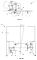
- FIGs. 1A,B schematically show a vehicle 1 comprising a chassis 2, built of two elongated, parallel U-beams 3, supported by a series of wheels 4 via a primary suspension 5, and a cabin 6, supported by the chassis 2 via a secondary suspension 7.
- the suspensions 5, 7 comprise spring means 8 and damping means 9, designed to isolate the cabin 6 from vibrations, which during use may occur in the vehicle 1, for instance when passing irregularities in a road surface.
- the spring stiffness of the spring means 8 ideally should be low. However, such a low spring stiffness will be accompanied by relatively large pitching motions of the cabin 6 during acceleration and deceleration of the vehicle 1 (i.e. back- and forward rotations of the cabin 6 as indicated by angle ⁇ in FIG.
- the spring stiffness should be high.
- these contradictory requirements regarding the spring stiffness are met by providing the primary and/or secondary suspension 5, 7 with an anti-roll/pitch system 10 of which an effective spring stiffness and an effective spring force (i.e. the spring stiffness and spring force as perceived at the sprung mass, e.g. the cabin 6, or the wheels 4) can be actively and dynamically adjusted, depending on the external load acting on the vehicle 1.
- an effective spring stiffness and an effective spring force i.e. the spring stiffness and spring force as perceived at the sprung mass, e.g. the cabin 6, or the wheels
- the suspension 7,10 comprises a bearing arm 12, which at one end is pivotally connected to a first vehicle mass, here: cabin 6, around a first pivot axis R 1 and with its opposite end is pivotally connected to a first leg 13A of an L-shaped subframe 13, around a second pivot axis R 2 .
- This subframe 13 is with said first leg 13A fixedly attached to a second vehicle mass, here: chassis beam 3, whereby a second leg 13B of the subframe 13 extends substantially horizontally, above the bearing arm 12.
- the bearing arm 12 is configured as a linkage triangle. It will be understood that in alternative embodiments, the arm 12 can be configured differently, for instance as a linkage rectangle or T-shaped rod.
- the arm 12 has a length L (as measured between the first and second pivot axes R 1,2 ).
- the suspension 7,10 furthermore comprises a spring 8, which is mounted on top of the second leg 13B of the subframe 13, wherein a centre line S of the spring 8 extends substantially perpendicular to said leg 13B, and intersects the bearing arm 12 approximately halfway its length L.
- the spring 8 is connected to the bearing arm 12 via an elongated flexible member 15, for instance a string or cable, which with a first end 15A is connected to the bearing arm 12, in a way to be described below, and with its opposite end 15B is connected to a cover plate 17, sitting on top of the spring 8.
- the spring 8 is compressed between the cover plate 17 and the bearing 16, thereby pre-tensioning the string 15 with a spring force F s .
- the string 15 is adjustably connected to the cover plate 17, for instance by means of a clamping element or a threaded connection 21, so that the magnitude of the pretension F s can be adjusted.
- the spring 8 is mounted on the subframe 13 by means of a bearing 16, e.g. a ball bearing, allowing the spring to rotate around its centre line S, thereby preventing the spring 8 from becoming twisted during use, which would affect its stiffness.
- a bearing 16 may also be incorporated in the cover plate 17 on top of the spring 8 (not shown).
- a guiding means may be provided between the bearing 16 and cover plate 17, so as to keep the spring 8 axially aligned during use. Such a guiding means may for instance not be needed when applying a steel coil compression spring with flat ends.
- the string 15 extends from the cover plate 17 centrally through the spring 8 and through an opening in the subframe leg 13B. From there, the string 15 is guided towards the bearing arm 12 via guiding means 14, so as to include an angle ⁇ with the spring centre line S, and connected to said arm 12 via a swivel arm 19, which is pivotally connected to the bearing arm 12, around a third pivot axis R 3 , extending in line with the spring centre line S.
- Drive means 20 are provided, such as an electric, pneumatic or hydraulic piston, arranged to rotate the swivel arm 19, causing the string end 15A, and hence the point of application of the spring force F s onto the bearing arm 12, to travel a circular path C, as indicated in dashed lines.
- the length of the swivel arm 19 and hence the radius r of the circular path C will affect the minimum and maximum counter acting moment M s attainable with the anti-roll/pitch system.
- said radius r is preferably chosen to be slightly smaller than half the bearing arm length L, as will be explained below.
- the suspension 7, 10 operates as follows. Under static load conditions, when the vehicle 1 stands still or rides stationary and no acceleration or deceleration forces act on the cabin 6, the suspension 7,10 takes on a neutral position as shown in FIG. 2, wherein the bearing arm 12 extends substantially horizontally and the swivel arm 19 extends substantially parallel to the first and second pivot axes R 1,2 . In this position, the bearing arm 12 will have to support a load P that equals approximately one fourth of the cabin weight, assuming the cabin 6 is supported by four suspensions 7,10, as shown in FIGs. 1A,B.
- the anti-roll/pitch system may be used as a load levelling system, wherein the spring force F s of the individual suspension systems may be set differently, to balance said unequal load distribution.
- sensors 30 may be provided to measure the dynamic load acting on the cabin 6, for instance by means of a force, acceleration, velocity and/or displacement measurement.
- a central control unit 35 may be provided, equipped with an algorithm to calculate on the basis of said measured data the instantaneous string position needed to compensate for the dynamic load, and to control the drive means 20 so as to effectuate this position by rotating the swivel arm 19.
- the spring 8 may be tiltably connected to the frame 13, so as to allow the spring 8, during use, especially during static load conditions, to be tilted in such way that its centre line S extends approximately in line with the elongated member 15, so that the elongated member 15 will be substantially free of bends. This may help to reduce or prevent wear and as such can increase the lifetime of said member 15. It may furthermore allow the system to take on an even more compact configuration, to meet additional space restrictions.
- the string or cable 15 can for instance be made of metal, in particular steel, or a high tensile strength material, such as Aramide fibres or the like.
- a tensile spring may be used to pre-tension the string 15.
- the guiding means 14 are preferably made of, or covered with low friction material, such as Teflon, and provided with a rounded contact surface. This will minimise the contact area and friction between the string 15 and the guiding means 14, which is beneficial for the lifetime of said components, as well as the force and energy needed to rotate the swivel arm 19.
- the guiding means 14 can for instance be provided with a bearing race, while the string 15 can be provided with a ball or comparable element, adapted to roll within said bearing race.
- a resilient layer 18, made of for instance natural or synthetic rubber, may be mounted between the subframe 13 and the chassis 2, as illustrated in FIG. 2, capable of absorbing or at least damping said vibrations.
- the cabin 6 is connected to the bearing arm 12 via a leaf spring 11, which is cantilevered in said cabin 6, as best seen in FIGs. 1B and 2.
- leaf spring 11 is stiff in a direction parallel to the first and second pivot axes R 1,2 , yet allows the cabin 6 to move in upward, downward and sideward direction, i.e. perpendicular to said pivot axes R 1,2 , thereby allowing the bearing arm 12 to oscillate around the second pivot axis R 2 , upon oscillation of spring 8, during use.
- FIG. 3 shows an alternative embodiment of an anti-roll/pitch system 10 according to the invention, wherein like parts have been denoted with like reference numerals.
- the embodiment mainly differs from the one shown in FIG. 2 in that the swivel arm 19 and piston assembly 20 are replaced by an electric motor 22, which is connected to the bearing arm 12 via a frame 23.
- the string 15 is eccentrically coupled to a shaft 24 of the motor 22, which is preferably supported on the bearing arm 12 by a cross roller bearing 25 or the like, capable of supporting the shaft 24 against axial and radial forces as well as a bending moment, which during use may be exerted on said shaft 24 by the pre-tensioned string 15.
- Reduction means 27 may be provided, enabling the shaft 24 to be driven with a desired couple and velocity.
- the system 10 operates in a similar way as described with regard to FIG. 2.
- the motor 22 can be provided with a hold provision 26, to shut down the motor 22 when the load thereon exceeds a predetermined value. This may happen when a rotation angle of the bearing arm 12 around its second pivot axis R 2 exceeds a certain value, due to oscillations of the spring 8. At such a large rotation angle, components of the spring force F s increase the load on the motor 22, requiring the motor to exert a larger couple and consume more energy to adjust the string position. Therefore, in a preferred embodiment the central control unit 35 may be arranged to activate the hold provision when the rotation angle of the bearing arm 12 around the second pivot axis R 2 exceeds a certain value, thereby relieving the motor 22. When the rotation angle returns in a predetermined, acceptable working range, the motor 22 can be activated again, so as to resume adjustment of the string position. As such, energy consumption of the system 10 can be optimised.
- the motor 22 can be provided with an encoder or comparable measurement means 32, to measure the position of the driven shaft 24. This information may be used by the central control unit 35 when controlling the motor 22, to adjust the string position.
- the system 10 may further comprise damping means 28, mounted between the bearing arm 12 and the subframe 13.
- damping means 28 mounted between the bearing arm 12 and the subframe 13.
- FIG. 2 may comprise a similar damping provision.
- the anti-roll/pitch system 10 has been illustrated as applied to a secondary suspension 7, between the chassis 2 and cabin 6. It will be clear, that the anti-roll/pitch system 10 can be applied on other vehicle suspensions in a comparable way, notably the primary suspension 5 between the chassis 2 and wheels 4, In that case the orientation of the spring 8 and string 15 may be reversed as compared to the orientation of the system shown in FIGs. 2 and 3, thereby allowing the system to withstand external pressure forces. This is schematically illustrated in FIG. 1B, for the left side wheel 4L.
- additional guiding means 34 may be applied to guide the elongated member 15 so as to subject the bearing arm 12 to a downward pulling force instead of an upward pulling spring force F s , as schematically illustrated in FIG. 1B, for the right side wheel 4R.
Priority Applications (8)
| Application Number | Priority Date | Filing Date | Title |
|---|---|---|---|
| EP04077360A EP1627756A1 (de) | 2004-08-20 | 2004-08-20 | Anti-roll/nicksystem für ein Fahrzeug und Fahrzeug mit einem solchen System |
| PCT/NL2005/000604 WO2006019298A1 (en) | 2004-08-20 | 2005-08-19 | Anti-roll/pitch system for use in a vehicle and vehicle equiped with such system |
| EP05779596A EP1824693B1 (de) | 2004-08-20 | 2005-08-19 | System zur verhinderung von quer- und längsneigung zur verwendung in einem fahrzeug und mit solch einem system ausgestattetes fahrzeug |
| ES05779596T ES2372403T3 (es) | 2004-08-20 | 2005-08-19 | Sistema de antibalanceo/anticabeceo para su utilización en un vehículo y vehículo equipado con dicho sistema. |
| CNB2005800280641A CN100564085C (zh) | 2004-08-20 | 2005-08-19 | 用于车辆的防侧倾/俯仰系统以及装配有该系统的车辆 |
| JP2007527082A JP5124271B2 (ja) | 2004-08-20 | 2005-08-19 | 車両用の耐ローリング/ピッチングシステムおよびそのシステムを備える車両 |
| US11/660,529 US7845660B2 (en) | 2004-08-20 | 2005-08-19 | Anti-roll/pitch system for use in a vehicle and vehicle equiped with such system |
| AT05779596T ATE527127T1 (de) | 2004-08-20 | 2005-08-19 | System zur verhinderung von quer- und längsneigung zur verwendung in einem fahrzeug und mit solch einem system ausgestattetes fahrzeug |
Applications Claiming Priority (1)
| Application Number | Priority Date | Filing Date | Title |
|---|---|---|---|
| EP04077360A EP1627756A1 (de) | 2004-08-20 | 2004-08-20 | Anti-roll/nicksystem für ein Fahrzeug und Fahrzeug mit einem solchen System |
Publications (1)
| Publication Number | Publication Date |
|---|---|
| EP1627756A1 true EP1627756A1 (de) | 2006-02-22 |
Family
ID=34928459
Family Applications (2)
| Application Number | Title | Priority Date | Filing Date |
|---|---|---|---|
| EP04077360A Withdrawn EP1627756A1 (de) | 2004-08-20 | 2004-08-20 | Anti-roll/nicksystem für ein Fahrzeug und Fahrzeug mit einem solchen System |
| EP05779596A Not-in-force EP1824693B1 (de) | 2004-08-20 | 2005-08-19 | System zur verhinderung von quer- und längsneigung zur verwendung in einem fahrzeug und mit solch einem system ausgestattetes fahrzeug |
Family Applications After (1)
| Application Number | Title | Priority Date | Filing Date |
|---|---|---|---|
| EP05779596A Not-in-force EP1824693B1 (de) | 2004-08-20 | 2005-08-19 | System zur verhinderung von quer- und längsneigung zur verwendung in einem fahrzeug und mit solch einem system ausgestattetes fahrzeug |
Country Status (7)
| Country | Link |
|---|---|
| US (1) | US7845660B2 (de) |
| EP (2) | EP1627756A1 (de) |
| JP (1) | JP5124271B2 (de) |
| CN (1) | CN100564085C (de) |
| AT (1) | ATE527127T1 (de) |
| ES (1) | ES2372403T3 (de) |
| WO (1) | WO2006019298A1 (de) |
Cited By (4)
| Publication number | Priority date | Publication date | Assignee | Title |
|---|---|---|---|---|
| EP1916129A1 (de) * | 2006-10-23 | 2008-04-30 | Nederlandse Organisatie voor toegepast-natuurwetenschappelijk Onderzoek TNO | Aktive Aufhängungsanordnung für ein Fahrzeug |
| WO2008154911A1 (de) * | 2007-06-20 | 2008-12-24 | Asturia Automotive Systems Ag | Fusspunktverstellung für fahrzeugfederungen |
| EP3147143A3 (de) * | 2015-07-31 | 2017-07-19 | Domin Tec Scout GmbH | Einrichtung und verfahren zur niveauregulierung einer fahrerkabine gegenüber einem fahrzeugrahmen und spindeltrieb für diese |
| CN111051091A (zh) * | 2017-10-09 | 2020-04-21 | 沃尔沃卡车集团 | 用于陆地车辆的驾驶室的悬挂系统 |
Families Citing this family (6)
| Publication number | Priority date | Publication date | Assignee | Title |
|---|---|---|---|---|
| US8181976B1 (en) * | 2008-06-21 | 2012-05-22 | Ross Brian A | Anti-binding spring mounting apparatus for vehicle suspension |
| BRPI0823072A2 (pt) * | 2008-09-08 | 2015-09-22 | Volvo Lastvagnar Ab | disposicao de painel dianteiro de veiculo |
| US20100152980A1 (en) * | 2008-12-15 | 2010-06-17 | Caterpillar, Inc. | Machine Employing Cab Mounts and Method for Controlling Cab Mounts to Based on Machine Location |
| EP2610129B1 (de) * | 2010-08-25 | 2020-04-15 | Nippon Steel Corporation | System zur messung der beschleunigung einer schwingungskomponente und methode zur messung der beschleunigung einer schwingungskomponente in einem schienenfahrzeug |
| DE102014201876A1 (de) * | 2014-02-03 | 2015-08-06 | Schaeffler Technologies AG & Co. KG | Vorrichtung zum Einstellen der Spur und/oder des Sturzes für ein Fahrwerk eines Kraftfahrzeugs |
| JP7056116B2 (ja) * | 2017-12-08 | 2022-04-19 | いすゞ自動車株式会社 | サスペンション装置 |
Citations (9)
| Publication number | Priority date | Publication date | Assignee | Title |
|---|---|---|---|---|
| GB159622A (en) * | 1919-12-03 | 1921-03-03 | George John Rackham | Improvements in means of suspension of vehicles |
| FR1503032A (fr) * | 1966-11-21 | 1967-11-24 | Suspension apport de force | |
| DE2538103A1 (de) * | 1975-08-27 | 1977-03-10 | Herbert Evertz | Federelement insbesondere fuer fahrzeuge |
| US4277085A (en) * | 1977-11-30 | 1981-07-07 | Bryansky Jury A | Transport vehicle |
| DE3707085A1 (de) * | 1986-03-13 | 1987-09-17 | Volkswagen Ag | Federungssystem fuer kraftfahrzeuge |
| DE3718390A1 (de) * | 1986-06-12 | 1987-12-17 | Volkswagen Ag | Federungssystem fuer kraftfahrzeuge |
| EP0639123A1 (de) | 1992-05-04 | 1995-02-22 | Univ Delft Tech | Masse-Feder-System Mit Wank-/Nickstabilisation für Anwendung in Fahrzeugen. |
| WO1999001305A1 (de) * | 1997-06-30 | 1999-01-14 | Forschungsinstitut Für Kraftfahrwesen Und Fahrzeugmotoren Stuttgart | Federungssystem |
| DE10105300A1 (de) * | 2001-02-02 | 2002-08-08 | Continental Teves Ag & Co Ohg | Federung mit veränderlicher Tragkraft für ein Kraftfahrzeug |
Family Cites Families (5)
| Publication number | Priority date | Publication date | Assignee | Title |
|---|---|---|---|---|
| US2885217A (en) | 1953-09-21 | 1959-05-05 | Felburn John Phil | Shock-absorbing vehicle suspension |
| FR1573973A (de) | 1968-03-28 | 1969-07-11 | ||
| JPS54100019A (en) * | 1977-11-30 | 1979-08-07 | Mo Abutomobiruno Dorozunii I | Vehicle |
| JPS63110012A (ja) * | 1986-10-24 | 1988-05-14 | フオルクスウアーゲン・アクチエンゲゼルシヤフト | 自動車用のばね懸架システム |
| GB2319760A (en) | 1996-11-30 | 1998-06-03 | Gec Alsthom Ltd | Mechanical actuator arrangement for a vehicle suspension system |
-
2004
- 2004-08-20 EP EP04077360A patent/EP1627756A1/de not_active Withdrawn
-
2005
- 2005-08-19 AT AT05779596T patent/ATE527127T1/de not_active IP Right Cessation
- 2005-08-19 EP EP05779596A patent/EP1824693B1/de not_active Not-in-force
- 2005-08-19 US US11/660,529 patent/US7845660B2/en not_active Expired - Fee Related
- 2005-08-19 WO PCT/NL2005/000604 patent/WO2006019298A1/en active Application Filing
- 2005-08-19 CN CNB2005800280641A patent/CN100564085C/zh not_active Expired - Fee Related
- 2005-08-19 JP JP2007527082A patent/JP5124271B2/ja not_active Expired - Fee Related
- 2005-08-19 ES ES05779596T patent/ES2372403T3/es active Active
Patent Citations (10)
| Publication number | Priority date | Publication date | Assignee | Title |
|---|---|---|---|---|
| GB159622A (en) * | 1919-12-03 | 1921-03-03 | George John Rackham | Improvements in means of suspension of vehicles |
| FR1503032A (fr) * | 1966-11-21 | 1967-11-24 | Suspension apport de force | |
| DE2538103A1 (de) * | 1975-08-27 | 1977-03-10 | Herbert Evertz | Federelement insbesondere fuer fahrzeuge |
| US4277085A (en) * | 1977-11-30 | 1981-07-07 | Bryansky Jury A | Transport vehicle |
| DE3707085A1 (de) * | 1986-03-13 | 1987-09-17 | Volkswagen Ag | Federungssystem fuer kraftfahrzeuge |
| DE3718390A1 (de) * | 1986-06-12 | 1987-12-17 | Volkswagen Ag | Federungssystem fuer kraftfahrzeuge |
| EP0639123A1 (de) | 1992-05-04 | 1995-02-22 | Univ Delft Tech | Masse-Feder-System Mit Wank-/Nickstabilisation für Anwendung in Fahrzeugen. |
| EP0639123B1 (de) * | 1992-05-04 | 1997-08-06 | Technische Universiteit Delft | Masse-feder-system mit wank-/nickstabilisierung für fahrzeuge |
| WO1999001305A1 (de) * | 1997-06-30 | 1999-01-14 | Forschungsinstitut Für Kraftfahrwesen Und Fahrzeugmotoren Stuttgart | Federungssystem |
| DE10105300A1 (de) * | 2001-02-02 | 2002-08-08 | Continental Teves Ag & Co Ohg | Federung mit veränderlicher Tragkraft für ein Kraftfahrzeug |
Cited By (8)
| Publication number | Priority date | Publication date | Assignee | Title |
|---|---|---|---|---|
| EP1916129A1 (de) * | 2006-10-23 | 2008-04-30 | Nederlandse Organisatie voor toegepast-natuurwetenschappelijk Onderzoek TNO | Aktive Aufhängungsanordnung für ein Fahrzeug |
| WO2008049845A1 (en) * | 2006-10-23 | 2008-05-02 | Nederlandse Organisatie Voor Toegepast-Natuurwetenschappelijk Onderzoek Tno | Active suspension assembly for a vehicle |
| CN101583506B (zh) * | 2006-10-23 | 2014-07-23 | 荷兰应用自然科学研究组织 | 车辆的主动悬挂组件 |
| WO2008154911A1 (de) * | 2007-06-20 | 2008-12-24 | Asturia Automotive Systems Ag | Fusspunktverstellung für fahrzeugfederungen |
| US8272650B2 (en) | 2007-06-20 | 2012-09-25 | Asturia Automotive Systems Ag | Low-end adjustment mechanism for vehicle suspensions |
| EP3147143A3 (de) * | 2015-07-31 | 2017-07-19 | Domin Tec Scout GmbH | Einrichtung und verfahren zur niveauregulierung einer fahrerkabine gegenüber einem fahrzeugrahmen und spindeltrieb für diese |
| WO2017020886A3 (de) * | 2015-07-31 | 2017-08-03 | Domin Tecscout Gmbh | Einrichtung und verfahren zur niveauregulierung einer fahrerkabine gegenüber einem fahrzeugrahmen und spindeltrieb für diese |
| CN111051091A (zh) * | 2017-10-09 | 2020-04-21 | 沃尔沃卡车集团 | 用于陆地车辆的驾驶室的悬挂系统 |
Also Published As
| Publication number | Publication date |
|---|---|
| CN101014472A (zh) | 2007-08-08 |
| ATE527127T1 (de) | 2011-10-15 |
| EP1824693B1 (de) | 2011-10-05 |
| WO2006019298A1 (en) | 2006-02-23 |
| EP1824693A1 (de) | 2007-08-29 |
| CN100564085C (zh) | 2009-12-02 |
| ES2372403T3 (es) | 2012-01-19 |
| US7845660B2 (en) | 2010-12-07 |
| JP2008510644A (ja) | 2008-04-10 |
| JP5124271B2 (ja) | 2013-01-23 |
| US20070252350A1 (en) | 2007-11-01 |
Similar Documents
| Publication | Publication Date | Title |
|---|---|---|
| US7845660B2 (en) | Anti-roll/pitch system for use in a vehicle and vehicle equiped with such system | |
| USRE48991E1 (en) | Operator ride enhancement system | |
| US3858902A (en) | Variable-load suspension for light vehicles | |
| US20060237885A1 (en) | Active seat suspension | |
| EP1782976B1 (de) | Elektronische Steuerung einer pneumatischen Aufhängung eines Fahrzeugs | |
| CA1264166A (en) | Apparatus for compensating transverse forces in automotive struts | |
| EP2214921B1 (de) | Fahrzeugaufhängung ausgestattet mit einer wankstabilisierungsanordnung | |
| JP5194019B2 (ja) | 車両用アクティブ・サスペンション装置 | |
| KR20170140286A (ko) | 조합 스프링 보상 서스펜션 장치 | |
| EP1902872A1 (de) | Aufhängungsvorrichtung für fahrzeug | |
| US8272672B2 (en) | Suspension device | |
| FI112460B (fi) | Ajokoneisto kiskoajoneuvoja varten | |
| CN210554842U (zh) | 磁浮车辆控制系统 | |
| KR20100054918A (ko) | 특수 차량의 선형 능동 현가 장치 | |
| US20030111501A1 (en) | ATV load support system | |
| EP2247491B1 (de) | Fahrerhauslagerungsanordnung und fahrerhauslagerung | |
| KR20060110381A (ko) | 차량용 현가장치 | |
| KR102606916B1 (ko) | 지상고 조절이 가능한 토션바형 차량용 충격 흡수장치 | |
| EP2337729B1 (de) | Kabinenaufhängungseinheit und fahrzeug mit wenigstens zwei kabinenaufhängungseinheiten | |
| KR20100054919A (ko) | 특수 차량의 암형 능동 현가 장치 | |
| KR100569331B1 (ko) | 횡력 저감용 차량의 스트럿 타입 현가장치 | |
| EP1527912B1 (de) | Aufhängung einer Starrachse in einem Fahrzeug, insbesondere Nutzfahrzeug | |
| EP4110650A1 (de) | Gelenkiges arbeitsmaschinenfahrzeug | |
| EP2470414A1 (de) | Raupenfahrzeug mit aufhängung | |
| KR20090006346A (ko) | 차량용 현가장치의 차고 조절형 베어링 |
Legal Events
| Date | Code | Title | Description |
|---|---|---|---|
| PUAI | Public reference made under article 153(3) epc to a published international application that has entered the european phase |
Free format text: ORIGINAL CODE: 0009012 |
|
| AK | Designated contracting states |
Kind code of ref document: A1 Designated state(s): AT BE BG CH CY CZ DE DK EE ES FI FR GB GR HU IE IT LI LU MC NL PL PT RO SE SI SK TR |
|
| AX | Request for extension of the european patent |
Extension state: AL HR LT LV MK |
|
| AKX | Designation fees paid | ||
| REG | Reference to a national code |
Ref country code: DE Ref legal event code: 8566 |
|
| STAA | Information on the status of an ep patent application or granted ep patent |
Free format text: STATUS: THE APPLICATION IS DEEMED TO BE WITHDRAWN |
|
| 18D | Application deemed to be withdrawn |
Effective date: 20060823 |