EP1626249A2 - Geomagnetischer Sensor für Selbstkalibrierung von Magnetfeldabweichung und Verfahren zur Verwendung davon. - Google Patents
Geomagnetischer Sensor für Selbstkalibrierung von Magnetfeldabweichung und Verfahren zur Verwendung davon. Download PDFInfo
- Publication number
- EP1626249A2 EP1626249A2 EP05254963A EP05254963A EP1626249A2 EP 1626249 A2 EP1626249 A2 EP 1626249A2 EP 05254963 A EP05254963 A EP 05254963A EP 05254963 A EP05254963 A EP 05254963A EP 1626249 A2 EP1626249 A2 EP 1626249A2
- Authority
- EP
- European Patent Office
- Prior art keywords
- axis
- magnetic field
- output values
- detection coils
- drive signal
- Prior art date
- Legal status (The legal status is an assumption and is not a legal conclusion. Google has not performed a legal analysis and makes no representation as to the accuracy of the status listed.)
- Withdrawn
Links
- 238000000034 method Methods 0.000 title claims abstract description 18
- 238000001514 detection method Methods 0.000 claims abstract description 82
- 238000004804 winding Methods 0.000 abstract description 5
- 230000000694 effects Effects 0.000 description 13
- 230000005358 geomagnetic field Effects 0.000 description 5
- 239000000463 material Substances 0.000 description 3
- 230000035699 permeability Effects 0.000 description 3
- 238000010276 construction Methods 0.000 description 2
- 238000010586 diagram Methods 0.000 description 2
- XEEYBQQBJWHFJM-UHFFFAOYSA-N iron Substances [Fe] XEEYBQQBJWHFJM-UHFFFAOYSA-N 0.000 description 2
- 229910052742 iron Inorganic materials 0.000 description 2
- 238000012545 processing Methods 0.000 description 2
- 239000013598 vector Substances 0.000 description 2
- 238000011161 development Methods 0.000 description 1
- 238000006073 displacement reaction Methods 0.000 description 1
- 229910052500 inorganic mineral Inorganic materials 0.000 description 1
- 239000000696 magnetic material Substances 0.000 description 1
- 230000005389 magnetism Effects 0.000 description 1
- 230000005415 magnetization Effects 0.000 description 1
- 238000005259 measurement Methods 0.000 description 1
- 239000011707 mineral Substances 0.000 description 1
- 238000012986 modification Methods 0.000 description 1
- 230000004048 modification Effects 0.000 description 1
- 230000002093 peripheral effect Effects 0.000 description 1
- 238000013139 quantization Methods 0.000 description 1
- 238000009738 saturating Methods 0.000 description 1
Images


Classifications
-
- G—PHYSICS
- G01—MEASURING; TESTING
- G01R—MEASURING ELECTRIC VARIABLES; MEASURING MAGNETIC VARIABLES
- G01R33/00—Arrangements or instruments for measuring magnetic variables
- G01R33/02—Measuring direction or magnitude of magnetic fields or magnetic flux
- G01R33/04—Measuring direction or magnitude of magnetic fields or magnetic flux using the flux-gate principle
- G01R33/05—Measuring direction or magnitude of magnetic fields or magnetic flux using the flux-gate principle in thin-film element
-
- G—PHYSICS
- G01—MEASURING; TESTING
- G01C—MEASURING DISTANCES, LEVELS OR BEARINGS; SURVEYING; NAVIGATION; GYROSCOPIC INSTRUMENTS; PHOTOGRAMMETRY OR VIDEOGRAMMETRY
- G01C17/00—Compasses; Devices for ascertaining true or magnetic north for navigation or surveying purposes
- G01C17/38—Testing, calibrating, or compensating of compasses
-
- G—PHYSICS
- G01—MEASURING; TESTING
- G01C—MEASURING DISTANCES, LEVELS OR BEARINGS; SURVEYING; NAVIGATION; GYROSCOPIC INSTRUMENTS; PHOTOGRAMMETRY OR VIDEOGRAMMETRY
- G01C17/00—Compasses; Devices for ascertaining true or magnetic north for navigation or surveying purposes
- G01C17/02—Magnetic compasses
- G01C17/28—Electromagnetic compasses
- G01C17/30—Earth-inductor compasses
Definitions
- Apparatuses and methods consistent with the present invention relate to using a geomagnetic sensor for auto-calibration of a deviation of a magnetic field, and more particularly, to a geomagnetic sensor for auto-calibration of a deviation of a magnetic field using a strength and an azimuth of the magnetic field calibrated using output values detected from separated detection coils and a method of using the same.
- a geomagnetic sensor measures a strength and a direction of a geomagnetism field.
- the geomagnetic sensor include a hole sensor using a hole effect, a superconducting quantum interference device (SQID) sensor using a quantization effect, a fluxgate type sensor using a saturation area of a magnetization curve, and the like.
- SQL superconducting quantum interference device
- the fluxgate type sensor is mostly used to measure a geomagnetism, in particular, to measure a geomagnetic field and detect minerals, space, the sea bottom, or the like.
- the fluxgate type sensor includes a soft magnetic property core formed of a high permeability material, an exciting coil winding around the soft magnetic property core, and a detection coil.
- the basic detection principle of the fluxgate type sensor uses non-linear magnetic characteristics saturating the soft magnetic property core by generating a magnetic field in the exciting coil using an alternating current and to measure the strength of an external magnetic field by measuring second harmonic voltage components proportional to the external magnetic field.
- the magnetic field detection method of the fluxgate type sensor includes second harmonic wave detection, pulse position detection, pulse magnitude detection, and so on. The second harmonic wave detection is mainly used.
- MEMS Micro Electro Mechanical System
- FIG. 1 is a view illustrating a conventional fluxgate including a separate type exciting coil.
- the conventional fluxgate includes cores 5, an exciting coil 1 winding around the cores 5, and a detection coil 3 wining around the cores 5.
- the cores 5 are formed of a high permeability material and may be a single line type core, two parallel cores, a ring type core, or the like. Two parallel cores and the conventional fluxgate including one detection coil 3 are shown in FIG. 1.
- the exciting coil 1 winds around the cores 5 in the solenoid form and receives an electric drive signal from an external source to excite the cores 5.
- the detection coil 3 also winds around the cores 5 in the solenoid form and detects an electromotive force from a magnetism generated by driving of the exciting coil 1.
- a geomagnetic sensor includes fluxgates to be orthogonal to each other as shown in FIG. 1.
- the fluxgates correspond to X-axis and Y-axis fluxgates.
- the geomagnetic sensor calculates a direction and strength of a magnetic field using output values output from the X-axis and Y-axis fluxgates.
- the strength of the magnetic field in a random position may be obtained by calculating an azimuth.
- the azimuth is ⁇
- the azimuth ⁇ is calculated as tan-1(Hy/Hx).
- Hx denotes the output value output from the X-axis fluxgate
- Hy denotes the output value output from the Y-axis fluxgate.
- FIGS. 2A and 2B illustrate the results of detecting a calibrated magnetic field, and of detecting a magnetic field that is not affected by an external magnetic field and the magnetic field that is affected by the external magnetic field.
- the strength of a magnetic field measured for X-axis and Y-axis fluxgates orthogonal to each other is calibrated, and the magnetic field forms a complete circle.
- a geomagnetic sensor system must 360° rotate to obtain the complete circle as shown in FIG. 2A.
- the center of a circle obtained by detecting a magnetic field is displaced in a direction of an external magnetic field due to an effect of the external magnetic field, and thus coordinate axes are displaced.
- a direction of the measured geomagnetism varies depending on the environment.
- a geomagnetic sensor is easily affected by a peripheral magnetic field such as buildings, iron bridges, subways, or the like, and an output signal of the geomagnetic sensor greatly varies according to an assembled state, an inclined degree, or the measurement environment of the buildings, the iron bridges, the subways, or the like.
- the geomagnetic sensor requires a calibration operation to measure an exact azimuth.
- an azimuth of a magnetic field may be changed sharply from ⁇ to ⁇ as shown in FIG. 2B.
- the center of the circle is moved by the affect of the external magnetic field, the movement of the center of the circle may not be calibrated.
- the direction of the magnetic field is detected as I not as II.
- an azimuth of a geomagnetic field is distorted, and thus the reliability of data is deteriorated.
- the center of the circle must be moved from point C to point C' in direction III to calibrate the effect of the external magnetic field.
- the geomagnetic sensor system must be rotated to detect output values of X and Y axes of the circle that is affected by the external magnetic field, so as to detect the center of the moved circle.
- U.S. Patent No. 4,953,305 discloses a system including a magnetic sensor and a microprocessor used for a vehicle in which a magnetic field is measured on X and Y axes, and a displacement of coordinate axes of a detected magnetic field exceeding a detection restriction area due to an external magnetic field is automatically calibrated.
- a slight variation in the direction of a geomagnetism due to a variation in the environment may be calibrated but a severe variation may not be calibrated.
- the disclosed calibration method varies with each vehicle. Also, before a geomagnetic system is mounted in the vehicle, a variation in the direction of a geomagnetism may not be calibrated. Even after the geomagnetic system is mounted in the vehicle, the vehicle must rotate 360° several times in order to calibrate the variation.
- U.S. Patent No. 5,390,122 discloses a method of operating an auto-calibration system when a system including a geomagnetic sensor moves at a speed of 16km/h. As disclosed in U.S. Patent No. 5,390,122, a vehicle is not rotated for calibration, but re-corrected data is compared with initial corrected data. However, data appropriate for calibrating the geomagnetic sensor may not be obtained according to proper circumstances.
- an aspect of the present general inventive concept is to provide a geomagnetic sensor for auto-calibration of a deviation of a magnetic field, for measuring a direction and a strength of the magnetic field regardless of an effect of an external magnetic field using X-axis and Y-axis output values detected from separate detection coils of a fluxgate, and a method using the geomagnetic sensor.
- a geomagnetic sensor for auto-calibration of a deviation of a magnetic field including: a geomagnetic detector including X-axis and Y-axis fluxgates orthogonal to each other and receiving a drive signal to detect an electromotive force corresponding to a geomagnetism; a signal processor converting the electromotive force output from the geomagnetic detector into X-axis and Y-axis output values and outputting the X-axis and Y-axis output values; and a drive signal generator applying the drive signal to the geomagnetic detector.
- Each of the X-axis and Y-axis fluxgates of the geomagnetic detector includes cores; a solenoid type exciting coil receiving the drive signal to excite the cores; and at least two detection coils winding around the cores in a solenoid form so as to detect the electromotive force induced by the cores and the exciting coil and having different numbers of turns.
- the geomagnetic sensor may further include a controller calculating an azimuth ⁇ based on the X-axis and Y-axis output values output from the signal processor.
- Each of the X-axis and Y-axis fluxgates may include the at least two detection coils, the numbers of turns of which are in a ratio of about 1:2.
- a method of auto-calibration of a deviation of a magnetic field of a geomagnetic sensor including X-axis and Y-axis fluxgates orthogonal to each other and each including at least two detection coils detecting an electromotive force corresponding to a geomagnetism, including: applying a drive signal to each of the X-axis and Y-axis fluxgates; detecting the electromotive force induced to the X-axis fluxgate from the at least two detection coils according to the drive signal and converting the electromotive force into predetermined X-axis output values; detecting the electromotive force induced to the Y-axis fluxgate from the at least two detection coils according to the drive signal and converting the electromotive force into predetermined Y-axis output values; and calculating a direction and a strength of a magnetic field based on a gradient of a straight line linking two of points on coordinates corresponding to the X-axis and
- Each of the X-axis and Y-axis fluxgates may include the at least two detection coils, of which the numbers of turns are in a ratio of about 1:2.
- FIG. 3A is a block diagram of a geomagnetic sensor according to an exemplary embodiment of the present invention.
- the geomagnetic sensor includes a drive signal generator 100, a geomagnetic detector 200, a signal processor 300, and a controller 400.
- the drive signal generator 100 generates and outputs a drive signal for driving the geomagnetic detector 200.
- the drive signal generally uses a pulse wave and a reversed pulse wave of the pulse wave.
- the geomagnetic detector 200 receives the drive signal from the drive signal generator 100 and outputs a predetermined electric signal corresponding to a geomagnetism.
- the geomagnetic detector 200 includes X-axis and Y-axis fluxgates orthogonal to each other.
- the signal processor 300 performs processing on the predetermined electric signal output from the geomagnetic detector 200 to convert the predetermined electric signal into a predetermined digital value, and outputs the digital value.
- the controller 400 controls components of the geomagnetic sensor and operates an azimuth using output values detected by the X-axis and Y-axis fluxgates.
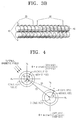
- FIG. 3B is a view of a part of the geomagnetic detector 200 of the geomagnetic sensor shown in FIG. 3A, that is, one of the X-axis and Y-axis fluxgates of the geomagnetic detector 200.
- the fluxgate of the geomagnetic detector 200 shown in FIG. 3B includes two detection coils, that is, first and second detection coils 20 and 30, but may include two or more detection coils.
- each of the X-axis and Y-axis fluxgates of the geomagnetic detector 200 includes an exciting coil 10, the first and second detection coils 20 and 30, and cores 40.
- the cores 40 are formed of a high magnetic permeability material and wounded by the exciting coil 10 and the first and second detection coils 20 and 30. A magnetic field is formed in the cores 40 by the exciting coil 10 upon receiving the drive signal.
- the exciting coil 10 receives the drive signal from the drive signal generator 100 to excite the cores 40 formed of a magnetic material. Directions of two portions of the exciting coil 10 winding around the cores 40 are opposite to each other according to the cores 40 that are parallel up and down. Thus, the magnetic field is formed in an opposite direction at the cores 40 excited by the exciting coil 10 receiving the drive signal.
- an electromotive force proportional to a strength of an external magnetic field is induced to the first and second detection coils 20 and 30.
- the electromotive force is detected from the first and second detection coils 20 and 30 of each of the X-axis and Y-axis fluxgates.
- the electromotive force induced to the first and second detection coils 20 and 30 is input to the signal processor 300.
- Directions along which the first and second detection coils 20 and 30 are formed may be the same or opposite.
- the directions along which the first and second detection coils 20 and 30 are formed are the same, points on coordinates formed by X-axis and Y-axis output values detected from the first and second detection coils 20 and 30 are positioned in the same direction based on the origin. In a case where the directions along which the first and second coils 20 and 30 are formed are opposite, the points on the coordinates formed by the X-axis and Y-axis output values detected from the first and second detection coils 20 and 30 are positioned in opposite directions based on the origin.
- the number of turns of the first detection coil 20 and the number of turns of the second detection coil 30 are in the ratio of 1:2. However, the ratio of the numbers of turns of the first and second detection coils 20 and 30 may vary.
- FIG. 4 illustrates X-axis and Y-axis output values and an azimuth detected by a geomagnetic sensor according to an exemplary embodiment of the present invention.
- X-axis and Y-axis output values and an azimuth that are not affected by an external magnetic field are represented on coordinates of Hx and Hy axes.
- X-axis and Y-axis output values and an azimuth that are affected by the external magnetic field are represented on coordinates of Hx' and Hy' axes.
- Outer circles denote X-axis and Y-axis output values detected by the first detection coil 20
- inner circles denote X-axis and Y-axis output values detected by the second detection coil 30.
- ⁇ denotes an azimuth
- ⁇ denotes an angle by which the center of the X-axis and Y-axis output values is moved by the external magnetic field.
- (Xc1, Yc1) and (Xc2, Yc2), respectively, are centers represented before and after the effect of the external magnetic field.
- X11 and Y11, and X12 and Y12 are the X-axis and Y-axis output values detected by the first and second detection coils 20 and 30 before the effect of the external magnetic field.
- X21 and Y21, and X22 and Y22 are the X-axis and Y-axis output values detected by the first and second detection coils 20 and 30 after the effect of the external magnetic field.
- A1 and A2 are points on X-axis and Y-axis coordinates represented before the effect of the external magnetic field
- B1 and B2 are points on the X-axis and Y-axis coordinates represented after the effect of the external magnetic field.
- a direction of a magnetic field that is not affected by the external magnetic field is a gradient of a straight line linking the origin O to the point A1, and the gradient of the straight line linking the origin O to the point A1 is equal to a gradient of a straight line linking the points A1 and A2.
- the direction of the magnetic field that is affected by the external magnetic field is a gradient of a straight line linking the origin O' moved by the external magnetic field to the point B1, and the gradient is equal to a gradient of a straight line linking the points B1 and B2 detected by the first and second detection coils 20 and 30.
- the points A1 and A2 are relatively moved to the points B1 and B2 due to the effect of the external magnetic field.
- the gradient of the straight line linking the points A1 and A2 is equal to the gradient of the straight line linking the points B1 and B2.
- the moved origin O' is not obtained by rotating and calibrating the geomagnetic sensor, the direction and strength of the magnetic field can be obtained using only the X-axis and Y-axis output values detected by the first and second detection coils 20 and 30 that are separated from each other.
- Equation 1 X11 and Y11 are the X-axis and Y-axis output values that are not affected by the external magnetic field and detected by the first detection coil 20, and X12 and Y12 are the X-axis and Y-axis output values that are not affected by the external magnetic field and detected by the second detection coil 30.
- X21 and Y21 are the X-axis and Y-axis output values that are affected by the external magnetic field and detected by the first detection coil 20
- X22 and Y22 are the X-axis and Y-axis output values that are affected by the external magnetic field and detected by the second detection coil 30.
- the azimuth of the magnetic field is an arc tangent value of a gradient of a straight line linking two points detected by the first and second detection coils 20 and 30.
- the result of Equation 1 is equal to the result of Equation 2.
- the gradient of the straight line linking the two points on the coordinates represented by the X-axis and Y-axis output values that are not affected by the external magnetic field and detected by the first and second detection coils 20 and 30 is equal to the gradient of the straight line linking the two points on the coordinates represented by the X-axis and Y-axis output values that are affected by the external magnetic field and detected by the first and second detection coils 20 and 30.
- the azimuth of the magnetic field does not vary irrespective of the external magnetic field.
- the directions along which the first and second detection coils 20 and 30 are formed are the same.
- points on coordinates represented by output values detected by the first detection coil 20 and points on coordinates represented by output values detected by the second detection coil 30 are formed as vectors in the same direction in a first quadrant on coordinates based on the origin.
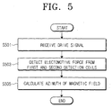
- FIG. 5 is a flowchart of a method of auto-calibration of a deviation of a geomagnetic field according to an exemplary embodiment of the present invention.
- the exciting coil 10 receives the drive signal from the drive signal generator 100.
- the exciting coil 10 excites the cores 40 of the geomagnetic detector 200.
- the electromotive force proportional to the strength of the external magnetic field is induced to the first and second detection coils 20 and 30.
- the electromotive force proportional to the strength of the external magnetic field is detected from the first and second detection coils 20 and 30.
- the electromotive force induced to the first and second detection coils 20 and 30 are output to the signal processor 300.
- the signal processor 300 performs the predetermined processing on the electric signal detected by the first and second detection coils 20 and 30 to convert the electric signal into the predetermined digital value.
- the direction and azimuth of the magnetic field are calculated using the electric signal detected by the first and second detection coils 20 and 30.
- the X-axis and Y-axis output values detected by the first and second detection coils 20 and 30 and moved by the external magnetic field are used without having to detect the origin moved by the external magnetic field in the circle representing the X-axis and Y-axis output values.
- the gradient of the straight line linking two points on the coordinates represented by the output values detected by the first and second detection coils 20 and 30 relatively moved by the effect of the external magnetic field is equal to the gradient that is not affected by the external magnetic field.
- the direction and azimuth of the magnetic field are detected by calculating a gradient of a straight line linking two points represented by output values detected by the first and second detection coils 20 and 30, not by calculating the azimuth using a gradient of a straight line linking the origin to a point on coordinates represented by the output values detected by the first detection coil 20 or a gradient of a straight line linking the origin to a point on coordinates represented by the output values detected by the second detection coil 30.
- the method of detecting the direction and azimuth of the magnetic field are as described with reference to FIG. 4.
- the azimuth is calculated by the controller 400 using the output values detected by the first and second detection coils 20 and 30 as in Equation 2 above.
- a geomagnetic sensor for auto-calibration of deviation and a method of using the same according to the present invention, detection coils of a geomagnetic detector can be separated from each other. An azimuth can be measured using output values detected by the separated detection coils. As a result, the azimuth can be exactly and easily detected regardless of an external magnetic field.
Landscapes
- Physics & Mathematics (AREA)
- Engineering & Computer Science (AREA)
- Radar, Positioning & Navigation (AREA)
- Remote Sensing (AREA)
- General Physics & Mathematics (AREA)
- Life Sciences & Earth Sciences (AREA)
- Environmental & Geological Engineering (AREA)
- General Life Sciences & Earth Sciences (AREA)
- Geology (AREA)
- Electromagnetism (AREA)
- Condensed Matter Physics & Semiconductors (AREA)
- Measuring Magnetic Variables (AREA)
Applications Claiming Priority (1)
| Application Number | Priority Date | Filing Date | Title |
|---|---|---|---|
| KR1020040062351A KR100579483B1 (ko) | 2004-08-09 | 2004-08-09 | 자기장 왜곡을 자동 보정하는 지자기 센서 및 그 방법 |
Publications (2)
| Publication Number | Publication Date |
|---|---|
| EP1626249A2 true EP1626249A2 (de) | 2006-02-15 |
| EP1626249A3 EP1626249A3 (de) | 2009-01-14 |
Family
ID=35311561
Family Applications (1)
| Application Number | Title | Priority Date | Filing Date |
|---|---|---|---|
| EP05254963A Withdrawn EP1626249A3 (de) | 2004-08-09 | 2005-08-09 | Geomagnetischer Sensor für Selbstkalibrierung von Magnetfeldabweichung und Verfahren zur Verwendung davon. |
Country Status (4)
| Country | Link |
|---|---|
| US (1) | US7181857B2 (de) |
| EP (1) | EP1626249A3 (de) |
| JP (1) | JP2006053146A (de) |
| KR (1) | KR100579483B1 (de) |
Families Citing this family (8)
| Publication number | Priority date | Publication date | Assignee | Title |
|---|---|---|---|---|
| KR100594971B1 (ko) * | 2004-01-09 | 2006-06-30 | 삼성전자주식회사 | 지자기 센서를 이용한 입력장치 및 이를 이용한 입력신호생성방법 |
| US8825426B2 (en) | 2010-04-09 | 2014-09-02 | CSR Technology Holdings Inc. | Method and apparatus for calibrating a magnetic sensor |
| DE102012218609A1 (de) * | 2012-10-12 | 2014-04-17 | Robert Bosch Gmbh | Magnetfeld-Erfassungsvorrichtung und Magnetfeld-Erfassungsverfahren |
| CN102927984B (zh) * | 2012-10-26 | 2015-03-11 | 哈尔滨工程大学 | 消除载体磁化磁场对地磁测量影响的方法 |
| CN103926627B (zh) * | 2014-04-23 | 2016-08-17 | 吉林大学 | 水下载体地磁三分量测量方法 |
| JP6021238B1 (ja) * | 2015-10-11 | 2016-11-09 | マグネデザイン株式会社 | グラジオセンサ素子およびグラジオセンサ |
| KR102306795B1 (ko) * | 2019-11-21 | 2021-09-30 | (재)한국나노기술원 | 콘텍 압력 센싱 장치 및 전자 기기 |
| CN112525224B (zh) * | 2020-12-23 | 2024-04-09 | 北京小米移动软件有限公司 | 磁场校准方法、磁场校准装置及存储介质 |
Citations (2)
| Publication number | Priority date | Publication date | Assignee | Title |
|---|---|---|---|---|
| US4953305A (en) | 1987-05-27 | 1990-09-04 | Prince Corporation | Vehicle compass with automatic continuous calibration |
| US5390122A (en) | 1993-05-07 | 1995-02-14 | Lectron Products, Inc. | Method and apparatus for calibrating a vehicle compass system |
Family Cites Families (8)
| Publication number | Priority date | Publication date | Assignee | Title |
|---|---|---|---|---|
| JPS5924260A (ja) * | 1982-07-31 | 1984-02-07 | Saura Keiki Seisakusho:Kk | マグネツトメ−タの設定方向測定方式 |
| JPH03501159A (ja) * | 1987-04-14 | 1991-03-14 | イギリス国 | ロールの影響を受けない磁力計システム |
| JPH1123683A (ja) * | 1997-06-27 | 1999-01-29 | Shimadzu Corp | 2軸フラックスゲート型磁気センサ |
| DE69925573T2 (de) * | 1999-05-12 | 2006-04-27 | Asulab S.A. | Magnetischer F?hler hergestellt auf einem halbleitenden Substrat |
| KR100464097B1 (ko) * | 2002-03-14 | 2005-01-03 | 삼성전자주식회사 | 반도체기판에 집적된 자계검출소자 및 그 제조방법 |
| KR100464098B1 (ko) * | 2002-03-14 | 2005-01-03 | 삼성전기주식회사 | 인쇄회로기판에 집적된 자계검출소자 및 그 제조방법 |
| KR100494472B1 (ko) * | 2002-12-31 | 2005-06-10 | 삼성전기주식회사 | 인쇄회로기판 기술을 이용한 미약자계 감지용 센서 및 그제조 방법 |
| US6972563B2 (en) * | 2004-03-04 | 2005-12-06 | Rosemount Aerospace Inc. | Method of adjusting a fluxgate magnetometer apparatus |
-
2004
- 2004-08-09 KR KR1020040062351A patent/KR100579483B1/ko not_active Expired - Fee Related
-
2005
- 2005-08-09 US US11/199,117 patent/US7181857B2/en not_active Expired - Fee Related
- 2005-08-09 JP JP2005231132A patent/JP2006053146A/ja not_active Ceased
- 2005-08-09 EP EP05254963A patent/EP1626249A3/de not_active Withdrawn
Patent Citations (2)
| Publication number | Priority date | Publication date | Assignee | Title |
|---|---|---|---|---|
| US4953305A (en) | 1987-05-27 | 1990-09-04 | Prince Corporation | Vehicle compass with automatic continuous calibration |
| US5390122A (en) | 1993-05-07 | 1995-02-14 | Lectron Products, Inc. | Method and apparatus for calibrating a vehicle compass system |
Also Published As
| Publication number | Publication date |
|---|---|
| EP1626249A3 (de) | 2009-01-14 |
| KR20060013761A (ko) | 2006-02-14 |
| JP2006053146A (ja) | 2006-02-23 |
| US7181857B2 (en) | 2007-02-27 |
| KR100579483B1 (ko) | 2006-05-15 |
| US20060026849A1 (en) | 2006-02-09 |
Similar Documents
| Publication | Publication Date | Title |
|---|---|---|
| US11693067B2 (en) | Magnetic sensor system | |
| EP2413153B1 (de) | Magnetdetektionsvorrichtung | |
| EP3321638A1 (de) | Messung einer absoluten winkelposition | |
| US10976383B2 (en) | Magnetic sensor device | |
| US20200340794A1 (en) | Method and apparatus for measuring angle between two bodies of foldable device | |
| JP2007248477A (ja) | 勾配の影響を補償し方位角を演算する地磁気センサー、およびその演算方法 | |
| US20080116888A1 (en) | Three-axis fluxgate-type magnetism detecting device and method | |
| KR100574506B1 (ko) | 연산된 방위각의 오류여부를 표시하는 지자기센서 및 그방위각측정방법 | |
| JP2007113993A (ja) | 磁気コンパス | |
| EP1626249A2 (de) | Geomagnetischer Sensor für Selbstkalibrierung von Magnetfeldabweichung und Verfahren zur Verwendung davon. | |
| US7155837B2 (en) | Geomagnetic sensor for detecting dip angle and method thereof | |
| US7162807B2 (en) | Geomagnetic sensor having a dip angle detection function and dip angle detection method therefor | |
| US9816888B2 (en) | Sensor and method for detecting a position of an effective surface of the sensor | |
| JP2009222542A (ja) | 磁気センサ素子および電子方位計 | |
| US20050016006A1 (en) | Magnetic compass | |
| JP2004286613A (ja) | 方位計測システム | |
| JPS5824811A (ja) | 方位検出装置 | |
| JP4611178B2 (ja) | 磁気方位検出装置及びその方位演算方法 | |
| JP3754289B2 (ja) | 携帯端末機器用姿勢角度検出装置および携帯端末機器用磁気方位検出装置 | |
| Včelák et al. | Electronic compass with miniature fluxgate sensors | |
| JP4928875B2 (ja) | センサーモジュール | |
| KR20090012724A (ko) | 3축 박막 플럭스게이트 센서와 3축 가속도 센서를 사용하여절대 방위를 판별하는 방법 | |
| KR19980051744A (ko) | 전자방위센서의 위치오차보정방법 |
Legal Events
| Date | Code | Title | Description |
|---|---|---|---|
| PUAI | Public reference made under article 153(3) epc to a published international application that has entered the european phase |
Free format text: ORIGINAL CODE: 0009012 |
|
| AK | Designated contracting states |
Kind code of ref document: A2 Designated state(s): AT BE BG CH CY CZ DE DK EE ES FI FR GB GR HU IE IS IT LI LT LU LV MC NL PL PT RO SE SI SK TR |
|
| AX | Request for extension of the european patent |
Extension state: AL BA HR MK YU |
|
| PUAL | Search report despatched |
Free format text: ORIGINAL CODE: 0009013 |
|
| AK | Designated contracting states |
Kind code of ref document: A3 Designated state(s): AT BE BG CH CY CZ DE DK EE ES FI FR GB GR HU IE IS IT LI LT LU LV MC NL PL PT RO SE SI SK TR |
|
| AX | Request for extension of the european patent |
Extension state: AL BA HR MK YU |
|
| RIC1 | Information provided on ipc code assigned before grant |
Ipc: G01R 33/05 20060101ALI20081208BHEP Ipc: G01C 17/38 20060101ALI20081208BHEP Ipc: G01C 17/30 20060101AFI20051121BHEP |
|
| AKX | Designation fees paid | ||
| REG | Reference to a national code |
Ref country code: DE Ref legal event code: 8566 |
|
| STAA | Information on the status of an ep patent application or granted ep patent |
Free format text: STATUS: THE APPLICATION IS DEEMED TO BE WITHDRAWN |
|
| 18D | Application deemed to be withdrawn |
Effective date: 20090715 |