EP1626168A2 - Moteur comprenant un système de refroidissement d'air optimalisé - Google Patents
Moteur comprenant un système de refroidissement d'air optimalisé Download PDFInfo
- Publication number
- EP1626168A2 EP1626168A2 EP05017248A EP05017248A EP1626168A2 EP 1626168 A2 EP1626168 A2 EP 1626168A2 EP 05017248 A EP05017248 A EP 05017248A EP 05017248 A EP05017248 A EP 05017248A EP 1626168 A2 EP1626168 A2 EP 1626168A2
- Authority
- EP
- European Patent Office
- Prior art keywords
- charge air
- engine
- air cooler
- cylinder
- cooler
- Prior art date
- Legal status (The legal status is an assumption and is not a legal conclusion. Google has not performed a legal analysis and makes no representation as to the accuracy of the status listed.)
- Withdrawn
Links
Images
Classifications
-
- F—MECHANICAL ENGINEERING; LIGHTING; HEATING; WEAPONS; BLASTING
- F02—COMBUSTION ENGINES; HOT-GAS OR COMBUSTION-PRODUCT ENGINE PLANTS
- F02B—INTERNAL-COMBUSTION PISTON ENGINES; COMBUSTION ENGINES IN GENERAL
- F02B29/00—Engines characterised by provision for charging or scavenging not provided for in groups F02B25/00, F02B27/00 or F02B33/00 - F02B39/00; Details thereof
- F02B29/04—Cooling of air intake supply
- F02B29/045—Constructional details of the heat exchangers, e.g. pipes, plates, ribs, insulation, materials, or manufacturing and assembly
- F02B29/0475—Constructional details of the heat exchangers, e.g. pipes, plates, ribs, insulation, materials, or manufacturing and assembly the intake air cooler being combined with another device, e.g. heater, valve, compressor, filter or EGR cooler, or being assembled on a special engine location
-
- Y—GENERAL TAGGING OF NEW TECHNOLOGICAL DEVELOPMENTS; GENERAL TAGGING OF CROSS-SECTIONAL TECHNOLOGIES SPANNING OVER SEVERAL SECTIONS OF THE IPC; TECHNICAL SUBJECTS COVERED BY FORMER USPC CROSS-REFERENCE ART COLLECTIONS [XRACs] AND DIGESTS
- Y02—TECHNOLOGIES OR APPLICATIONS FOR MITIGATION OR ADAPTATION AGAINST CLIMATE CHANGE
- Y02T—CLIMATE CHANGE MITIGATION TECHNOLOGIES RELATED TO TRANSPORTATION
- Y02T10/00—Road transport of goods or passengers
- Y02T10/10—Internal combustion engine [ICE] based vehicles
- Y02T10/12—Improving ICE efficiencies
Definitions
- This invention relates to internal combustion engines and, more particularly, to an engine with an efficient, optimized charge air-cooling system that provides lower engine cylinder air inlet temperatures resulting in reduced NOx emissions and improved fuel economy.
- charge air coolers it is known in the art of internal combustion engines, especially those engines used for transportation vehicles, to use charge air coolers to cool hot, compressed charge air discharged from a compressor, such as a turbocharger, prior to delivery to the engine combustion chambers.
- Charge air coolers are used to cool and reduce the volume of the compressed intake air to increase the mass of the inlet air charge and to operate with cooler combustion temperatures.
- NOx nitrogen oxides
- the present invention provides a high efficiency charge air cooler (aftercooler) having a core volume which is substantially increased over the size of previous aftercooler designs relative to the total cylinder displacement of the engines to which they are applied.
- aftercooler core/engine displacement ratios for various somewhat comparable railway locomotive engines vary from about 0.32 to about 0.85 while the ratio for the GM model V265H engine is increased to 1.19, an increase from about 40 percent to 372 percent.
- a charge air cooler is placed outboard of each engine cylinder bank along the side of the engine and extends the full length of the associated engine cylinder bank.
- a charge air-cooling system in accordance with the present invention includes a charge air cooler side mounted along an outboard side of each engine cylinder bank of a V-type engine.
- the charge air coolers extend along the full length of the engine cylinder banks.
- the charge air coolers may each include a housing having an air inlet and an air outlet.
- the air inlet is connected through an intake header to an outlet of a charge air source of the engine, such as a turbocharger compressor.
- the air outlet is connected through a cooler outlet header, acting as an engine intake manifold, to intake ports of cylinders of the engine, through which the cooled charge air passes from the air cooler outlet header to the cylinders.
- the charge air coolers may have full length heat exchanger cores fixed at only one end in the housing and free floating on supports along their length to allow for expansion/contraction due to temperature changes.
- Each charge air cooler may further include a four pass cross flow heat exchanger core having an airside and a coolant side.
- the airsides of the heat exchangers may each be connected to their respective charge air cooler housing inlet and outlet.
- the maximum pressure drop across the airside of the heat exchanger may be on the order of 1 ⁇ 2 psi.
- the coolant used for the coolant side of the heat exchanger may be a propylene glycol and water mixture.
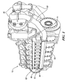
- FIG. 1 is a perspective view of a turbocharged diesel engine including an optimized charge air-cooling system in accordance with the present invention.
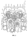
- FIG. 2 is a transverse cross-sectional view of the embodiment of FIG. 1.
- numeral 10 generally indicates a GM model 12V265H turbocharged diesel engine designed for railway locomotive applications but usable in other applications, such as marine power and mobile and stationary power plants.
- Engine 10 includes an optimized engine charge air-cooling system 12 in accordance with the present invention.
- Charge air-cooling system 12 achieves a reduction in the amount of NOx produced by the engine while at the same time increasing fuel economy and engine reliability.
- the engine 10 has two cylinder banks 14, each having a plurality of cylinders 16 closed by cylinder heads 18. Pistons 20, reciprocable within the cylinders, define variable volume combustion chambers 22 between the pistons 20 and cylinder heads 18.
- the cylinder heads 18 contain intake and exhaust ports 24, 26, respectively, that communicate with the combustion chambers and are controlled by intake and exhaust valves 28, 30, respectively, which are mounted in the cylinder heads and biased by valve springs 32.
- the valves 28, 30 are mechanically actuated by intake and exhaust cams 34, 36, respectively, of a camshaft 38 driving an associated valve actuating mechanism such as intake rocker arm 40.
- Fuel injection valves 42 are pressure actuated by camshaft driven injection pumps 43.
- the exhaust ports 26 are connected to exhaust manifolds 44, which are in turn connected to turbochargers 46.
- the charge air-cooling system 12 includes charge air coolers 48 that are side mounted to each of the outboard sides of the cylinder banks 14 of the engine 10. As illustrated in FIG. 1, the charge air coolers 48 extend along the full length of the engine cylinder banks 14.
- the charge air coolers 48 each include a housing 50 and a heat exchanger core 52 within the housing.
- the core 52 is fixed at only one end to the housing 50 and is free floating along its length on supports in the housing. This allows for expansion of the core 52 as the temperature of the core increases.
- Each charge air cooler core 52 may also be arranged on the coolant side as a four pass cross flow heat exchanger.
- Each charge air cooler housing 50 includes an air inlet 54 and an air outlet 56.
- the charge air-cooler air inlet 54 is connected through an intake header 58 to an air outlet 60 of a compressed air source, in this case a turbocharger 46.
- the charge air cooler air outlet 56 is connected through a cooler outlet header 62, acting as an engine intake manifold, to the cylinder intake ports 24.
- the engine cycle conventionally includes intake, compression, expansion and exhaust strokes of the pistons.
- Intake charges drawn into the combustion chambers 22 from the cylinder intake ports 24 on the intake strokes are compressed with the valves closed.
- Fuel injected into the combustion chambers 22 is ignited by the compressed gases, and the burned gases expand, producing power. High combustion temperatures in the combustion chambers undesirably cause formation of nitrogen oxides (NOx).
- NOx nitrogen oxides
- the combustion products are exhausted through the exhaust ports 26 and exhaust manifolds 44 to the turbochargers 46, providing energy to the turbochargers to boost the pressure of the intake charges.
- the engine pistons draw air into their respective combustion chambers on their intake strokes.
- the turbochargers 46 draw in additional charge air and compress the air, thereby heating it.
- the pressurized (compressed) charge air is delivered through the turbocharger air outlets 60 and intake headers 58 to the charge air cooler housing inlets 54. Charge air then passes through the heat exchanger cores 52 and exits through the charge air cooler housing outlets 56. Finally, the charge air passes through the cooler outlet headers 62 to the cylinder intake ports 34 at pressures varying with engine operating conditions.
- the charge air-cooling system 12 effectively controls NOx production without a loss of fuel economy or engine reliability. In fact, the charge air-cooling system 12 reduces NOx emissions and improves fuel economy. The charge air-cooling system 12 achieves this result by lowering the temperature of the air before it enters the combustion chambers 22 without causing a significant loss of pressure.
- the charge air cooler 48 is designed as a four pass cross flow heat exchanger arrangement and used with a propylene glycol and water mixture as the engine and charge air cooler coolant, the effectiveness of the heat exchange is in the range of 94 to 96 percent. Effectiveness is defined as 100 times the difference between the compressor discharge temperature and the cooler discharge temperature divided by the difference between the compressor discharge temperature and the coolant inlet temperature.
Applications Claiming Priority (1)
| Application Number | Priority Date | Filing Date | Title |
|---|---|---|---|
| US10/914,816 US6976479B1 (en) | 2004-08-10 | 2004-08-10 | Engine with optimized engine charge air-cooling system |
Publications (2)
| Publication Number | Publication Date |
|---|---|
| EP1626168A2 true EP1626168A2 (fr) | 2006-02-15 |
| EP1626168A3 EP1626168A3 (fr) | 2011-06-08 |
Family
ID=34978767
Family Applications (1)
| Application Number | Title | Priority Date | Filing Date |
|---|---|---|---|
| EP05017248A Withdrawn EP1626168A3 (fr) | 2004-08-10 | 2005-08-08 | Moteur comprenant un système de refroidissement d'air optimalisé |
Country Status (3)
| Country | Link |
|---|---|
| US (1) | US6976479B1 (fr) |
| EP (1) | EP1626168A3 (fr) |
| CN (1) | CN100400817C (fr) |
Families Citing this family (11)
| Publication number | Priority date | Publication date | Assignee | Title |
|---|---|---|---|---|
| CA2474415A1 (fr) * | 2004-07-15 | 2006-01-15 | Gerald Hayes | Refroidisseur auxiliere pour un moteur situe dans un building |
| US8066950B2 (en) * | 2005-12-19 | 2011-11-29 | Miratech Holdings, Llc | Catalytic converter system and element for diesel engines |
| US20070163243A1 (en) * | 2006-01-17 | 2007-07-19 | Arvin Technologies, Inc. | Exhaust system with cam-operated valve assembly and associated method |
| DE102008046507A1 (de) * | 2008-09-09 | 2010-03-11 | Behr Industry Gmbh & Co. Kg | Ladeluftkühler, insbesondere für Großmotoren |
| DE102009053884A1 (de) * | 2009-11-20 | 2011-06-01 | Behr Gmbh & Co. Kg | Saugrohr für einen Verbrennungsmotor |
| DE102010029691B4 (de) * | 2010-06-03 | 2012-02-16 | Mtu Friedrichshafen Gmbh | Brennkraftmaschine und Ladefluid-Kühler |
| WO2012017521A1 (fr) * | 2010-08-03 | 2012-02-09 | トヨタ自動車株式会社 | Structure de refroidissement pour véhicules |
| DE102011078751A1 (de) * | 2011-07-06 | 2013-01-10 | Behr Gmbh & Co. Kg | Saugrohre, Ladeluftkühler, Saugrohrmodul, Motorsystem und Verfahren zur Dimensionierung derselben |
| US9581024B2 (en) | 2014-05-21 | 2017-02-28 | Achates Power, Inc. | Air handling constructions for opposed-piston engines |
| US9551220B2 (en) | 2014-05-21 | 2017-01-24 | Achates Power, Inc. | Open intake and exhaust chamber constructions for an air handling system of an opposed-piston engine |
| WO2019084098A1 (fr) * | 2017-10-26 | 2019-05-02 | 500 Group, Inc. | Systèmes d'admission/d'échappement d'air de moteur personnalisables |
Citations (5)
| Publication number | Priority date | Publication date | Assignee | Title |
|---|---|---|---|---|
| FR2117158A5 (fr) * | 1970-12-02 | 1972-07-21 | Kloeckner Humboldt Deutz Ag | |
| DE4000917A1 (de) * | 1989-02-07 | 1990-08-09 | Avl Verbrennungskraft Messtech | Luftgekuehlte brennkraftmaschine |
| WO2000040844A1 (fr) * | 1999-01-08 | 2000-07-13 | Lysholm Technologies Ab | Dispositif d'un moteur a combustion interne a suralimentation |
| US20040144091A1 (en) * | 2002-12-19 | 2004-07-29 | Budhadeb Mahakul | Emission reduction kit for EMD diesel engines |
| DE102004049027A1 (de) * | 2004-10-08 | 2006-04-20 | Audi Ag | Verbrennungskraftmaschine und Ladermodul für eine Verbrennungskraftmaschine |
Family Cites Families (11)
| Publication number | Priority date | Publication date | Assignee | Title |
|---|---|---|---|---|
| GB1326503A (en) * | 1971-04-27 | 1973-08-15 | Semt | Supercharged internal combustion engines |
| US4385594A (en) * | 1981-08-03 | 1983-05-31 | Deere & Company | Two-circuit cooling system and pump for an engine |
| JPS6128719A (ja) * | 1984-07-17 | 1986-02-08 | Yanmar Diesel Engine Co Ltd | V形機関の過給装置 |
| FR2645209B1 (fr) * | 1989-03-28 | 1991-07-19 | Ecia Equip Composants Ind Auto | Dispositif compact echangeur thermique-repartiteur de gaz, notamment pour moteur thermique compresse |
| DE4017823C2 (de) * | 1990-06-02 | 1995-04-06 | Mtu Friedrichshafen Gmbh | Ansauganlage für eine Brennkraftmaschine zur Verwendung bei ein- oder zweistufiger Aufladung |
| CN1032709C (zh) * | 1993-02-23 | 1996-09-04 | H·奥霍兹基 | 运行一种船用柴油机的方法 |
| SE502710C2 (sv) * | 1994-11-24 | 1995-12-11 | Valeo Engine Cooling Ab | Anordning vid en förbränningsmotors insugningsrör |
| US6279550B1 (en) * | 1996-07-17 | 2001-08-28 | Clyde C. Bryant | Internal combustion engine |
| JPH10281014A (ja) * | 1997-04-02 | 1998-10-20 | Calsonic Corp | Egrガス冷却装置 |
| DE19840616C1 (de) * | 1998-09-05 | 1999-12-02 | Daimler Chrysler Ag | Brennkraftmaschine in V-Bauweise mit einem mechanisch angetriebenen Lader |
| FI116802B (fi) * | 2002-01-17 | 2006-02-28 | Waertsilae Finland Oy | Mäntämoottorin imuilmajärjestely |
-
2004
- 2004-08-10 US US10/914,816 patent/US6976479B1/en not_active Expired - Fee Related
-
2005
- 2005-08-08 EP EP05017248A patent/EP1626168A3/fr not_active Withdrawn
- 2005-08-10 CN CNB2005101098101A patent/CN100400817C/zh not_active Expired - Fee Related
Patent Citations (5)
| Publication number | Priority date | Publication date | Assignee | Title |
|---|---|---|---|---|
| FR2117158A5 (fr) * | 1970-12-02 | 1972-07-21 | Kloeckner Humboldt Deutz Ag | |
| DE4000917A1 (de) * | 1989-02-07 | 1990-08-09 | Avl Verbrennungskraft Messtech | Luftgekuehlte brennkraftmaschine |
| WO2000040844A1 (fr) * | 1999-01-08 | 2000-07-13 | Lysholm Technologies Ab | Dispositif d'un moteur a combustion interne a suralimentation |
| US20040144091A1 (en) * | 2002-12-19 | 2004-07-29 | Budhadeb Mahakul | Emission reduction kit for EMD diesel engines |
| DE102004049027A1 (de) * | 2004-10-08 | 2006-04-20 | Audi Ag | Verbrennungskraftmaschine und Ladermodul für eine Verbrennungskraftmaschine |
Also Published As
| Publication number | Publication date |
|---|---|
| CN1755076A (zh) | 2006-04-05 |
| US6976479B1 (en) | 2005-12-20 |
| EP1626168A3 (fr) | 2011-06-08 |
| CN100400817C (zh) | 2008-07-09 |
Similar Documents
| Publication | Publication Date | Title |
|---|---|---|
| EP1626168A2 (fr) | Moteur comprenant un système de refroidissement d'air optimalisé | |
| US9470133B2 (en) | Engine having integrated exhaust manifold with combined ducts for inside cylinders and outside cylinders | |
| CN103362632B (zh) | 用于内燃机的进气系统 | |
| US6460337B1 (en) | Combustion engine | |
| CN102257258B (zh) | 用于内燃机的排气装置 | |
| CN100545429C (zh) | 复合六行程自冷式内燃引擎 | |
| US4028892A (en) | Turbocharged two-cycle engine with positive blower and internally mounted aftercooler | |
| US3232042A (en) | Engine turbocharging systems | |
| US20060174621A1 (en) | Two-turbocharger engine and method | |
| CN104185728B (zh) | 量调节的四冲程往复活塞式内燃机和用于运行四冲程往复活塞式内燃机的方法 | |
| US20160265487A1 (en) | Engine with exhaust gas recirculation | |
| RU2638901C2 (ru) | Двигатель внутреннего сгорания с наддувом и способ работы двигателя внутреннего сгорания с наддувом | |
| CN104121123A (zh) | 具有脉冲抑制的专用排气再循环的发动机 | |
| AU2010246385A1 (en) | Engine with charge air-cooling system with water fumigation | |
| US20080168770A1 (en) | Cooling system for an engine having high pressure EGR and machine using same | |
| US20220235717A1 (en) | Internal Combustion Engine with Cooling Assist System for Manifold Intake Temperature Reduction | |
| EP0985809A2 (fr) | Moteur a combustion interne et a pistons "naida" | |
| US6866028B2 (en) | Emission reduction kit for EMD diesel engines | |
| JP2001280130A (ja) | エンジンの冷却構造 | |
| US20230086779A1 (en) | Structural arrangement in a low-temperature turbocompressor using other power connections | |
| JP3608668B2 (ja) | インタークーラー付きディーゼルエンジン | |
| SU1758261A1 (ru) | Двигатель внутреннего сгорани | |
| JP2020084890A (ja) | Egr装置 | |
| Hiereth et al. | Examples of supercharged production engines | |
| KR19980034452U (ko) | TCI 엔진의 흡입 공기 프리 쿨링(Pre-cooling) 구조 |
Legal Events
| Date | Code | Title | Description |
|---|---|---|---|
| PUAI | Public reference made under article 153(3) epc to a published international application that has entered the european phase |
Free format text: ORIGINAL CODE: 0009012 |
|
| AK | Designated contracting states |
Kind code of ref document: A2 Designated state(s): AT BE BG CH CY CZ DE DK EE ES FI FR GB GR HU IE IS IT LI LT LU LV MC NL PL PT RO SE SI SK TR |
|
| AX | Request for extension of the european patent |
Extension state: AL BA HR MK YU |
|
| PUAL | Search report despatched |
Free format text: ORIGINAL CODE: 0009013 |
|
| AK | Designated contracting states |
Kind code of ref document: A3 Designated state(s): AT BE BG CH CY CZ DE DK EE ES FI FR GB GR HU IE IS IT LI LT LU LV MC NL PL PT RO SE SI SK TR |
|
| AX | Request for extension of the european patent |
Extension state: AL BA HR MK YU |
|
| 17P | Request for examination filed |
Effective date: 20111104 |
|
| AKX | Designation fees paid |
Designated state(s): AT BE BG CH CY CZ DE DK EE ES FI FR GB GR HU IE IS IT LI LT LU LV MC NL PL PT RO SE SI SK TR |
|
| 17Q | First examination report despatched |
Effective date: 20160219 |
|
| STAA | Information on the status of an ep patent application or granted ep patent |
Free format text: STATUS: THE APPLICATION IS DEEMED TO BE WITHDRAWN |
|
| 18D | Application deemed to be withdrawn |
Effective date: 20160630 |