EP1626168A2 - Engine with optimized engine charge air-cooling system - Google Patents
Engine with optimized engine charge air-cooling system Download PDFInfo
- Publication number
- EP1626168A2 EP1626168A2 EP05017248A EP05017248A EP1626168A2 EP 1626168 A2 EP1626168 A2 EP 1626168A2 EP 05017248 A EP05017248 A EP 05017248A EP 05017248 A EP05017248 A EP 05017248A EP 1626168 A2 EP1626168 A2 EP 1626168A2
- Authority
- EP
- European Patent Office
- Prior art keywords
- charge air
- engine
- air cooler
- cylinder
- cooler
- Prior art date
- Legal status (The legal status is an assumption and is not a legal conclusion. Google has not performed a legal analysis and makes no representation as to the accuracy of the status listed.)
- Withdrawn
Links
Images
Classifications
-
- F—MECHANICAL ENGINEERING; LIGHTING; HEATING; WEAPONS; BLASTING
- F02—COMBUSTION ENGINES; HOT-GAS OR COMBUSTION-PRODUCT ENGINE PLANTS
- F02B—INTERNAL-COMBUSTION PISTON ENGINES; COMBUSTION ENGINES IN GENERAL
- F02B29/00—Engines characterised by provision for charging or scavenging not provided for in groups F02B25/00, F02B27/00 or F02B33/00 - F02B39/00; Details thereof
- F02B29/04—Cooling of air intake supply
- F02B29/045—Constructional details of the heat exchangers, e.g. pipes, plates, ribs, insulation, materials, or manufacturing and assembly
- F02B29/0475—Constructional details of the heat exchangers, e.g. pipes, plates, ribs, insulation, materials, or manufacturing and assembly the intake air cooler being combined with another device, e.g. heater, valve, compressor, filter or EGR cooler, or being assembled on a special engine location
-
- Y—GENERAL TAGGING OF NEW TECHNOLOGICAL DEVELOPMENTS; GENERAL TAGGING OF CROSS-SECTIONAL TECHNOLOGIES SPANNING OVER SEVERAL SECTIONS OF THE IPC; TECHNICAL SUBJECTS COVERED BY FORMER USPC CROSS-REFERENCE ART COLLECTIONS [XRACs] AND DIGESTS
- Y02—TECHNOLOGIES OR APPLICATIONS FOR MITIGATION OR ADAPTATION AGAINST CLIMATE CHANGE
- Y02T—CLIMATE CHANGE MITIGATION TECHNOLOGIES RELATED TO TRANSPORTATION
- Y02T10/00—Road transport of goods or passengers
- Y02T10/10—Internal combustion engine [ICE] based vehicles
- Y02T10/12—Improving ICE efficiencies
Definitions
- This invention relates to internal combustion engines and, more particularly, to an engine with an efficient, optimized charge air-cooling system that provides lower engine cylinder air inlet temperatures resulting in reduced NOx emissions and improved fuel economy.
- charge air coolers it is known in the art of internal combustion engines, especially those engines used for transportation vehicles, to use charge air coolers to cool hot, compressed charge air discharged from a compressor, such as a turbocharger, prior to delivery to the engine combustion chambers.
- Charge air coolers are used to cool and reduce the volume of the compressed intake air to increase the mass of the inlet air charge and to operate with cooler combustion temperatures.
- NOx nitrogen oxides
- the present invention provides a high efficiency charge air cooler (aftercooler) having a core volume which is substantially increased over the size of previous aftercooler designs relative to the total cylinder displacement of the engines to which they are applied.
- aftercooler core/engine displacement ratios for various somewhat comparable railway locomotive engines vary from about 0.32 to about 0.85 while the ratio for the GM model V265H engine is increased to 1.19, an increase from about 40 percent to 372 percent.
- a charge air cooler is placed outboard of each engine cylinder bank along the side of the engine and extends the full length of the associated engine cylinder bank.
- a charge air-cooling system in accordance with the present invention includes a charge air cooler side mounted along an outboard side of each engine cylinder bank of a V-type engine.
- the charge air coolers extend along the full length of the engine cylinder banks.
- the charge air coolers may each include a housing having an air inlet and an air outlet.
- the air inlet is connected through an intake header to an outlet of a charge air source of the engine, such as a turbocharger compressor.
- the air outlet is connected through a cooler outlet header, acting as an engine intake manifold, to intake ports of cylinders of the engine, through which the cooled charge air passes from the air cooler outlet header to the cylinders.
- the charge air coolers may have full length heat exchanger cores fixed at only one end in the housing and free floating on supports along their length to allow for expansion/contraction due to temperature changes.
- Each charge air cooler may further include a four pass cross flow heat exchanger core having an airside and a coolant side.
- the airsides of the heat exchangers may each be connected to their respective charge air cooler housing inlet and outlet.
- the maximum pressure drop across the airside of the heat exchanger may be on the order of 1 ⁇ 2 psi.
- the coolant used for the coolant side of the heat exchanger may be a propylene glycol and water mixture.
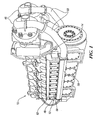
- FIG. 1 is a perspective view of a turbocharged diesel engine including an optimized charge air-cooling system in accordance with the present invention.
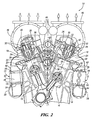
- FIG. 2 is a transverse cross-sectional view of the embodiment of FIG. 1.
- numeral 10 generally indicates a GM model 12V265H turbocharged diesel engine designed for railway locomotive applications but usable in other applications, such as marine power and mobile and stationary power plants.
- Engine 10 includes an optimized engine charge air-cooling system 12 in accordance with the present invention.
- Charge air-cooling system 12 achieves a reduction in the amount of NOx produced by the engine while at the same time increasing fuel economy and engine reliability.
- the engine 10 has two cylinder banks 14, each having a plurality of cylinders 16 closed by cylinder heads 18. Pistons 20, reciprocable within the cylinders, define variable volume combustion chambers 22 between the pistons 20 and cylinder heads 18.
- the cylinder heads 18 contain intake and exhaust ports 24, 26, respectively, that communicate with the combustion chambers and are controlled by intake and exhaust valves 28, 30, respectively, which are mounted in the cylinder heads and biased by valve springs 32.
- the valves 28, 30 are mechanically actuated by intake and exhaust cams 34, 36, respectively, of a camshaft 38 driving an associated valve actuating mechanism such as intake rocker arm 40.
- Fuel injection valves 42 are pressure actuated by camshaft driven injection pumps 43.
- the exhaust ports 26 are connected to exhaust manifolds 44, which are in turn connected to turbochargers 46.
- the charge air-cooling system 12 includes charge air coolers 48 that are side mounted to each of the outboard sides of the cylinder banks 14 of the engine 10. As illustrated in FIG. 1, the charge air coolers 48 extend along the full length of the engine cylinder banks 14.
- the charge air coolers 48 each include a housing 50 and a heat exchanger core 52 within the housing.
- the core 52 is fixed at only one end to the housing 50 and is free floating along its length on supports in the housing. This allows for expansion of the core 52 as the temperature of the core increases.
- Each charge air cooler core 52 may also be arranged on the coolant side as a four pass cross flow heat exchanger.
- Each charge air cooler housing 50 includes an air inlet 54 and an air outlet 56.
- the charge air-cooler air inlet 54 is connected through an intake header 58 to an air outlet 60 of a compressed air source, in this case a turbocharger 46.
- the charge air cooler air outlet 56 is connected through a cooler outlet header 62, acting as an engine intake manifold, to the cylinder intake ports 24.
- the engine cycle conventionally includes intake, compression, expansion and exhaust strokes of the pistons.
- Intake charges drawn into the combustion chambers 22 from the cylinder intake ports 24 on the intake strokes are compressed with the valves closed.
- Fuel injected into the combustion chambers 22 is ignited by the compressed gases, and the burned gases expand, producing power. High combustion temperatures in the combustion chambers undesirably cause formation of nitrogen oxides (NOx).
- NOx nitrogen oxides
- the combustion products are exhausted through the exhaust ports 26 and exhaust manifolds 44 to the turbochargers 46, providing energy to the turbochargers to boost the pressure of the intake charges.
- the engine pistons draw air into their respective combustion chambers on their intake strokes.
- the turbochargers 46 draw in additional charge air and compress the air, thereby heating it.
- the pressurized (compressed) charge air is delivered through the turbocharger air outlets 60 and intake headers 58 to the charge air cooler housing inlets 54. Charge air then passes through the heat exchanger cores 52 and exits through the charge air cooler housing outlets 56. Finally, the charge air passes through the cooler outlet headers 62 to the cylinder intake ports 34 at pressures varying with engine operating conditions.
- the charge air-cooling system 12 effectively controls NOx production without a loss of fuel economy or engine reliability. In fact, the charge air-cooling system 12 reduces NOx emissions and improves fuel economy. The charge air-cooling system 12 achieves this result by lowering the temperature of the air before it enters the combustion chambers 22 without causing a significant loss of pressure.
- the charge air cooler 48 is designed as a four pass cross flow heat exchanger arrangement and used with a propylene glycol and water mixture as the engine and charge air cooler coolant, the effectiveness of the heat exchange is in the range of 94 to 96 percent. Effectiveness is defined as 100 times the difference between the compressor discharge temperature and the cooler discharge temperature divided by the difference between the compressor discharge temperature and the coolant inlet temperature.
Abstract
Description
- This invention relates to internal combustion engines and, more particularly, to an engine with an efficient, optimized charge air-cooling system that provides lower engine cylinder air inlet temperatures resulting in reduced NOx emissions and improved fuel economy.
- It is known in the art of internal combustion engines, especially those engines used for transportation vehicles, to use charge air coolers to cool hot, compressed charge air discharged from a compressor, such as a turbocharger, prior to delivery to the engine combustion chambers. Charge air coolers are used to cool and reduce the volume of the compressed intake air to increase the mass of the inlet air charge and to operate with cooler combustion temperatures.
- Regulations controlling emissions of nitrogen oxides (NOx) are becoming increasingly difficult to meet. Problematically, however, most engine modifications that reduce NOx production concurrently cause the negative result of decreased fuel economy. Therefore, a need exists for an engine having reduced NOx emissions without reduced fuel economy.
- Through testing we have discovered that there is an operating change that improves emissions (reduces NOx), reduces fuel consumption, and improves reliability. We have found that by lowering the temperature of air entering the engine cylinders relative to ambient temperature, NOx levels drop and fuel consumption is reduced. As a result, we have developed an optimized design for charge air cooling of GM 12 and 16 cylinder model V265H turbocharged diesel engines designed primarily for use in railway locomotives but usable for other vehicle and stationary applications. The inventive concepts of the design may be applicable to other engine configurations and applications as well as to the engine models indicated.
- The present invention provides a high efficiency charge air cooler (aftercooler) having a core volume which is substantially increased over the size of previous aftercooler designs relative to the total cylinder displacement of the engines to which they are applied. For example, aftercooler core/engine displacement ratios for various somewhat comparable railway locomotive engines vary from about 0.32 to about 0.85 while the ratio for the GM model V265H engine is increased to 1.19, an increase from about 40 percent to 372 percent.
- In the preferred embodiment, a charge air cooler is placed outboard of each engine cylinder bank along the side of the engine and extends the full length of the associated engine cylinder bank. The unique use in a medium speed, four-stroke cycle diesel engine having a central camshaft in combination with a 45-degree "V" arrangement makes the engine narrow enough to accept charge air coolers along the length of the sides of the engine. This arrangement of charge air coolers along the length of the engine bank in turn allows for the increased charge air cooler capacity.
- Because of the large area of the heat exchanger in the present charge air coolers, they achieve highly effective cooling of the air entering the cylinders relative to the ambient temperatures. This high level of effectiveness is also achieved with a very low pressure drop across the airside of the heat exchangers, on the order of ½ psi under maximum flow conditions. This improved arrangement results in the levels of NOx produced by the engine desirably dropping while fuel economy is improved.
- A charge air-cooling system in accordance with the present invention includes a charge air cooler side mounted along an outboard side of each engine cylinder bank of a V-type engine. The charge air coolers extend along the full length of the engine cylinder banks. The charge air coolers may each include a housing having an air inlet and an air outlet. The air inlet is connected through an intake header to an outlet of a charge air source of the engine, such as a turbocharger compressor. The air outlet is connected through a cooler outlet header, acting as an engine intake manifold, to intake ports of cylinders of the engine, through which the cooled charge air passes from the air cooler outlet header to the cylinders.
- In a preferred embodiment, the charge air coolers may have full length heat exchanger cores fixed at only one end in the housing and free floating on supports along their length to allow for expansion/contraction due to temperature changes. Each charge air cooler may further include a four pass cross flow heat exchanger core having an airside and a coolant side.
The airsides of the heat exchangers may each be connected to their respective charge air cooler housing inlet and outlet. The maximum pressure drop across the airside of the heat exchanger may be on the order of ½ psi. The coolant used for the coolant side of the heat exchanger may be a propylene glycol and water mixture. - These and other features and advantages of the invention will be more fully understood from the following description of certain specific embodiments of the invention taken together with the accompanying drawings.
- FIG. 1 is a perspective view of a turbocharged diesel engine including an optimized charge air-cooling system in accordance with the present invention; and
- FIG. 2 is a transverse cross-sectional view of the embodiment of FIG. 1.
- Referring now to FIGS. 1 and 2 of the drawings in detail,
numeral 10 generally indicates a GM model 12V265H turbocharged diesel engine designed for railway locomotive applications but usable in other applications, such as marine power and mobile and stationary power plants.Engine 10 includes an optimized engine charge air-cooling system 12 in accordance with the present invention. Charge air-cooling system 12 achieves a reduction in the amount of NOx produced by the engine while at the same time increasing fuel economy and engine reliability. - The
engine 10 has twocylinder banks 14, each having a plurality ofcylinders 16 closed bycylinder heads 18.Pistons 20, reciprocable within the cylinders, define variablevolume combustion chambers 22 between thepistons 20 andcylinder heads 18. Thecylinder heads 18 contain intake andexhaust ports exhaust valves valve springs 32. Thevalves exhaust cams intake rocker arm 40.Fuel injection valves 42 are pressure actuated by camshaft driven injection pumps 43. Theexhaust ports 26 are connected toexhaust manifolds 44, which are in turn connected toturbochargers 46. - In a preferred embodiment of the present invention, the charge air-
cooling system 12 includescharge air coolers 48 that are side mounted to each of the outboard sides of thecylinder banks 14 of theengine 10. As illustrated in FIG. 1, thecharge air coolers 48 extend along the full length of theengine cylinder banks 14. Theengine 10, having a central camshaft in combination with a 45-degree "V" arrangement, is narrow enough to accept thecharge air coolers 48 of the charge air-cooling system 12 along the length of outboard sides of theirrespective engine banks 14. Thecharge air coolers 48 each include ahousing 50 and aheat exchanger core 52 within the housing. Thecore 52 is fixed at only one end to thehousing 50 and is free floating along its length on supports in the housing. This allows for expansion of thecore 52 as the temperature of the core increases. Each chargeair cooler core 52 may also be arranged on the coolant side as a four pass cross flow heat exchanger. - Each charge
air cooler housing 50 includes anair inlet 54 and anair outlet 56. The charge air-cooler air inlet 54 is connected through anintake header 58 to anair outlet 60 of a compressed air source, in this case aturbocharger 46. The charge aircooler air outlet 56 is connected through acooler outlet header 62, acting as an engine intake manifold, to thecylinder intake ports 24. - The engine cycle conventionally includes intake, compression, expansion and exhaust strokes of the pistons. Intake charges drawn into the
combustion chambers 22 from thecylinder intake ports 24 on the intake strokes are compressed with the valves closed. Fuel injected into thecombustion chambers 22 is ignited by the compressed gases, and the burned gases expand, producing power. High combustion temperatures in the combustion chambers undesirably cause formation of nitrogen oxides (NOx). - The combustion products are exhausted through the
exhaust ports 26 andexhaust manifolds 44 to theturbochargers 46, providing energy to the turbochargers to boost the pressure of the intake charges. The engine pistons draw air into their respective combustion chambers on their intake strokes. At higher engine loads, theturbochargers 46 draw in additional charge air and compress the air, thereby heating it. The pressurized (compressed) charge air is delivered through theturbocharger air outlets 60 andintake headers 58 to the charge aircooler housing inlets 54. Charge air then passes through theheat exchanger cores 52 and exits through the charge aircooler housing outlets 56. Finally, the charge air passes through thecooler outlet headers 62 to thecylinder intake ports 34 at pressures varying with engine operating conditions. - The charge air-cooling
system 12 effectively controls NOx production without a loss of fuel economy or engine reliability. In fact, the charge air-coolingsystem 12 reduces NOx emissions and improves fuel economy. The charge air-coolingsystem 12 achieves this result by lowering the temperature of the air before it enters thecombustion chambers 22 without causing a significant loss of pressure. - Hot, compressed charge air enters the charge air cooler 48 from a compressed air source such as the
turbocharger 46. As the charge air passes through thecharge air cooler 48, the hot charge air is cooled. When thecharge air cooler 48 is designed as a four pass cross flow heat exchanger arrangement and used with a propylene glycol and water mixture as the engine and charge air cooler coolant, the effectiveness of the heat exchange is in the range of 94 to 96 percent. Effectiveness is defined as 100 times the difference between the compressor discharge temperature and the cooler discharge temperature divided by the difference between the compressor discharge temperature and the coolant inlet temperature. Because of the large area of the heat exchanger, made possible by extending the heat exchanger the full length of the engine cylinder bank, this high effectiveness is achieved with a very low pressure drop in the charge air across the airside of the exchanger. Under maximum flow conditions, this pressure drop is on the order of only ½ psi. The lowering of the charge air temperature, while simultaneously maintaining the pressure of the charge air, combines to reduce NOx production while reducing fuel consumption. - In summary, the invention emphasizes the following features:
- charge air coolers side mounted along outboard sides of an engine cylinder bank;
- charge air coolers extending the full length of the cylinder bank;
- a charge air-cooling system having highly effective charge air cooling with a very small drop in air pressure; and
- a charge air-cooling system that achieves reduced engine NOx emissions and reduced fuel consumption.
- While the invention has been described by reference to certain preferred embodiments, it should be understood that numerous changes could be made within the spirit and scope of the inventive concepts described. Accordingly, it is intended that the invention not be limited to the disclosed embodiments, but that it have the full scope permitted by the language of the following claims.
Claims (19)
- An internal combustion engine comprising:two opposite cylinder banks;a plurality of cylinders in each of said cylinder banks, said cylinders disposed in a V arrangement;a cylinder intake port connected to each of said cylinders;a cylinder exhaust port connected to each of said cylinders;two compressed air sources, each connected to said exhaust ports of the cylinders of one of said cylinder banks;a central camshaft located in between said two cylinder banks for actuating valves in both banks; andtwo charge air coolers, each comprising a housing, a core, an air inlet, and an air outlet;each charge air cooler housing side mounted along an outboard side of one of said cylinder banks;each of said charge air coolers cores extending for substantially the length of one of said cylinder banks;each of said charge air cooler air inlets being connected to an outlet of one of said compressed air sources;each of said charge air cooler air outlets being connected to said cylinder intake ports of the cylinders of one of said cylinder banks.
- The engine of claim 1 including a charge air cooler intake header connected between each of said compressed air source air outlets and said charge air cooler air inlets.
- The engine of claim 1 including a charge air cooler outlet header connected between each of said charge air cooler outlets and said intake ports of the cylinders of one of said cylinder banks.
- The engine of claim 1, wherein said compressed air sources are turbochargers.
- The engine of claim 1, wherein each of said charge air cooler cores is fixedly mounted at only one end of said housing and free floating on supports along the length of said housing.
- The engine of claim 1, wherein each of said charge air cooler cores is a four pass cross flow heat exchanger having an airside and a coolant side.
- The engine of claim 6, wherein said airside of each of said heat exchangers is connected to said charge air cooler inlet on side end and to said charge air cooler outlet on another side.
- The engine of claim 6, wherein maximum air pressure drop across the airside of each of said heat exchangers is on the order of ½ psi.
- The engine of claim 6, wherein a coolant used in said coolant side of said heat exchangers comprises a propylene glycol/water mixture.
- An internal combustion engine comprising:at least one cylinder bank;a plurality of cylinders in said cylinder bank;a cylinder intake port connected to each of said cylinders;a cylinder exhaust port connected to each of said cylinders;a compressed air source connected to said exhaust ports; andat least one charge air cooler comprising a housing, a core, an air inlet, and an air outlet;said charge air cooler housing side mounted along one side of said cylinder bank;said charge air cooler extending along the length of said cylinder bank;said charge air cooler air inlet being connected to an outlet of said compressed air source;said charge air cooler air outlet being connected to said cylinder intake ports.
- The engine of claim 10 including a charge air cooler intake header connected between said compressed air source air outlet and said charge air cooler air inlet.
- The engine of claim 10 including a charge air cooler outlet header connected between said charge air cooler outlet and said cylinder intake ports.
- The engine of claim 10, wherein said compressed air source is a turbocharger.
- The engine of claim 10, wherein said charge air cooler core is fixedly mounted at only one end of said housing and free floating on supports along the length of said housing.
- The engine of claim 10, wherein each of said charge air cooler cores is a four pass cross flow heat exchanger having an airside and a coolant side.
- The engine of claim 15, wherein said airside of said heat exchanger is connected to said charge air cooler inlet on one side and to said charge air cooler outlet on another side.
- The engine of claim 15, wherein maximum air pressure drop across the airside of said heat exchanger is on the order of ½ psi.
- The engine of claim 15, wherein a coolant used in said coolant side of said heat exchanger comprises a propylene glycol/water mixture.
- An engine charge air-cooling system for a transportation vehicle engine comprising:a charge air cooler having a housing and a core;said charge air cooler housing side mounted along an outboard side of an engine bank of a transportation vehicle engine;said charge air cooler extending the full length of said engine bank;said charge air cooler connected in between a compressed air source of said engine and a plurality of cylinder intake ports of said engine.
Applications Claiming Priority (1)
| Application Number | Priority Date | Filing Date | Title |
|---|---|---|---|
| US10/914,816 US6976479B1 (en) | 2004-08-10 | 2004-08-10 | Engine with optimized engine charge air-cooling system |
Publications (2)
| Publication Number | Publication Date |
|---|---|
| EP1626168A2 true EP1626168A2 (en) | 2006-02-15 |
| EP1626168A3 EP1626168A3 (en) | 2011-06-08 |
Family
ID=34978767
Family Applications (1)
| Application Number | Title | Priority Date | Filing Date |
|---|---|---|---|
| EP05017248A Withdrawn EP1626168A3 (en) | 2004-08-10 | 2005-08-08 | Engine with optimized engine charge air-cooling system |
Country Status (3)
| Country | Link |
|---|---|
| US (1) | US6976479B1 (en) |
| EP (1) | EP1626168A3 (en) |
| CN (1) | CN100400817C (en) |
Families Citing this family (11)
| Publication number | Priority date | Publication date | Assignee | Title |
|---|---|---|---|---|
| CA2474415A1 (en) * | 2004-07-15 | 2006-01-15 | Gerald Hayes | Auxillary cooler for an engine located in a building |
| US8066950B2 (en) * | 2005-12-19 | 2011-11-29 | Miratech Holdings, Llc | Catalytic converter system and element for diesel engines |
| US20070163243A1 (en) * | 2006-01-17 | 2007-07-19 | Arvin Technologies, Inc. | Exhaust system with cam-operated valve assembly and associated method |
| DE102008046507A1 (en) * | 2008-09-09 | 2010-03-11 | Behr Industry Gmbh & Co. Kg | Intercooler, especially for large engines |
| DE102009053884A1 (en) * | 2009-11-20 | 2011-06-01 | Behr Gmbh & Co. Kg | Suction tube for an internal combustion engine |
| DE102010029691B4 (en) * | 2010-06-03 | 2012-02-16 | Mtu Friedrichshafen Gmbh | Internal combustion engine and charging fluid cooler |
| US8752660B2 (en) * | 2010-08-03 | 2014-06-17 | Toyota Jidosha Kabushiki Kaisha | Cooling structure for vehicles |
| DE102011078751A1 (en) * | 2011-07-06 | 2013-01-10 | Behr Gmbh & Co. Kg | Suction pipes, intercooler, intake manifold module, engine system and method for dimensioning the same |
| US9581024B2 (en) | 2014-05-21 | 2017-02-28 | Achates Power, Inc. | Air handling constructions for opposed-piston engines |
| US9551220B2 (en) | 2014-05-21 | 2017-01-24 | Achates Power, Inc. | Open intake and exhaust chamber constructions for an air handling system of an opposed-piston engine |
| WO2019084098A1 (en) * | 2017-10-26 | 2019-05-02 | 500 Group, Inc. | Customizable engine air intake/exhaust systems |
Citations (5)
| Publication number | Priority date | Publication date | Assignee | Title |
|---|---|---|---|---|
| FR2117158A5 (en) * | 1970-12-02 | 1972-07-21 | Kloeckner Humboldt Deutz Ag | |
| DE4000917A1 (en) * | 1989-02-07 | 1990-08-09 | Avl Verbrennungskraft Messtech | AIR COOLED INTERNAL COMBUSTION ENGINE |
| WO2000040844A1 (en) * | 1999-01-08 | 2000-07-13 | Lysholm Technologies Ab | Means for a combustion engine having a super charger |
| US20040144091A1 (en) * | 2002-12-19 | 2004-07-29 | Budhadeb Mahakul | Emission reduction kit for EMD diesel engines |
| DE102004049027A1 (en) * | 2004-10-08 | 2006-04-20 | Audi Ag | Internal combustion engine with charging module for motor vehicle has charger with two flange plates extending sideways from charger housing |
Family Cites Families (11)
| Publication number | Priority date | Publication date | Assignee | Title |
|---|---|---|---|---|
| GB1326503A (en) * | 1971-04-27 | 1973-08-15 | Semt | Supercharged internal combustion engines |
| US4385594A (en) * | 1981-08-03 | 1983-05-31 | Deere & Company | Two-circuit cooling system and pump for an engine |
| JPS6128719A (en) * | 1984-07-17 | 1986-02-08 | Yanmar Diesel Engine Co Ltd | Supercharging device for v-type engine |
| FR2645209B1 (en) * | 1989-03-28 | 1991-07-19 | Ecia Equip Composants Ind Auto | COMPACT HEAT EXCHANGER-GAS DISTRIBUTOR DEVICE, IN PARTICULAR FOR A COMPRESSED HEAT ENGINE |
| DE4017823C2 (en) * | 1990-06-02 | 1995-04-06 | Mtu Friedrichshafen Gmbh | Intake system for an internal combustion engine for use with one- or two-stage supercharging |
| CN1032709C (en) * | 1993-02-23 | 1996-09-04 | H·奥霍兹基 | Process for operating a marine diesel engine |
| SE502710C2 (en) * | 1994-11-24 | 1995-12-11 | Valeo Engine Cooling Ab | Device at an internal combustion engine suction pipe |
| US6279550B1 (en) * | 1996-07-17 | 2001-08-28 | Clyde C. Bryant | Internal combustion engine |
| JPH10281014A (en) * | 1997-04-02 | 1998-10-20 | Calsonic Corp | Egr gas cooling device |
| DE19840616C1 (en) * | 1998-09-05 | 1999-12-02 | Daimler Chrysler Ag | V=engine with mechanically driven turbocharger |
| FI116802B (en) * | 2002-01-17 | 2006-02-28 | Waertsilae Finland Oy | Suction air arrangement for piston engine |
-
2004
- 2004-08-10 US US10/914,816 patent/US6976479B1/en not_active Expired - Fee Related
-
2005
- 2005-08-08 EP EP05017248A patent/EP1626168A3/en not_active Withdrawn
- 2005-08-10 CN CNB2005101098101A patent/CN100400817C/en not_active Expired - Fee Related
Patent Citations (5)
| Publication number | Priority date | Publication date | Assignee | Title |
|---|---|---|---|---|
| FR2117158A5 (en) * | 1970-12-02 | 1972-07-21 | Kloeckner Humboldt Deutz Ag | |
| DE4000917A1 (en) * | 1989-02-07 | 1990-08-09 | Avl Verbrennungskraft Messtech | AIR COOLED INTERNAL COMBUSTION ENGINE |
| WO2000040844A1 (en) * | 1999-01-08 | 2000-07-13 | Lysholm Technologies Ab | Means for a combustion engine having a super charger |
| US20040144091A1 (en) * | 2002-12-19 | 2004-07-29 | Budhadeb Mahakul | Emission reduction kit for EMD diesel engines |
| DE102004049027A1 (en) * | 2004-10-08 | 2006-04-20 | Audi Ag | Internal combustion engine with charging module for motor vehicle has charger with two flange plates extending sideways from charger housing |
Also Published As
| Publication number | Publication date |
|---|---|
| US6976479B1 (en) | 2005-12-20 |
| EP1626168A3 (en) | 2011-06-08 |
| CN1755076A (en) | 2006-04-05 |
| CN100400817C (en) | 2008-07-09 |
Similar Documents
| Publication | Publication Date | Title |
|---|---|---|
| EP1626168A2 (en) | Engine with optimized engine charge air-cooling system | |
| US9470133B2 (en) | Engine having integrated exhaust manifold with combined ducts for inside cylinders and outside cylinders | |
| CN103362632B (en) | For the gas handling system of internal-combustion engine | |
| US6460337B1 (en) | Combustion engine | |
| CN100545429C (en) | Dual six-stoke self-cooling internal combustion engine | |
| US4028892A (en) | Turbocharged two-cycle engine with positive blower and internally mounted aftercooler | |
| US3232042A (en) | Engine turbocharging systems | |
| US20060174621A1 (en) | Two-turbocharger engine and method | |
| CN104185728B (en) | Four stroke stroke piston combustion engines of amount regulation and the method for operation four stroke stroke piston combustion engines | |
| CN102257258A (en) | An exhaust arrangement for an internal combustion engine | |
| US20160265487A1 (en) | Engine with exhaust gas recirculation | |
| RU2638901C2 (en) | Supercharged internal combustion engine and method of operation of supercharged internal combustion engine | |
| CN104121123A (en) | Engine with pulse-suppressed dedicated exhaust gas recirculation | |
| AU2010246385A1 (en) | Engine with charge air-cooling system with water fumigation | |
| US20080168770A1 (en) | Cooling system for an engine having high pressure EGR and machine using same | |
| US20220235717A1 (en) | Internal Combustion Engine with Cooling Assist System for Manifold Intake Temperature Reduction | |
| EP0985809A2 (en) | Internal-combustion piston engine "naida" | |
| US6866028B2 (en) | Emission reduction kit for EMD diesel engines | |
| JP2001280130A (en) | Cooling structure for engine | |
| US20230086779A1 (en) | Structural arrangement in a low-temperature turbocompressor using other power connections | |
| JP3608668B2 (en) | Diesel engine with intercooler | |
| SU1758261A1 (en) | Internal combustion engine | |
| JP2020084890A (en) | EGR device | |
| Hiereth et al. | Examples of supercharged production engines | |
| KR19980034452U (en) | Intake air pre-cooling structure of TCI engine |
Legal Events
| Date | Code | Title | Description |
|---|---|---|---|
| PUAI | Public reference made under article 153(3) epc to a published international application that has entered the european phase |
Free format text: ORIGINAL CODE: 0009012 |
|
| AK | Designated contracting states |
Kind code of ref document: A2 Designated state(s): AT BE BG CH CY CZ DE DK EE ES FI FR GB GR HU IE IS IT LI LT LU LV MC NL PL PT RO SE SI SK TR |
|
| AX | Request for extension of the european patent |
Extension state: AL BA HR MK YU |
|
| PUAL | Search report despatched |
Free format text: ORIGINAL CODE: 0009013 |
|
| AK | Designated contracting states |
Kind code of ref document: A3 Designated state(s): AT BE BG CH CY CZ DE DK EE ES FI FR GB GR HU IE IS IT LI LT LU LV MC NL PL PT RO SE SI SK TR |
|
| AX | Request for extension of the european patent |
Extension state: AL BA HR MK YU |
|
| 17P | Request for examination filed |
Effective date: 20111104 |
|
| AKX | Designation fees paid |
Designated state(s): AT BE BG CH CY CZ DE DK EE ES FI FR GB GR HU IE IS IT LI LT LU LV MC NL PL PT RO SE SI SK TR |
|
| 17Q | First examination report despatched |
Effective date: 20160219 |
|
| STAA | Information on the status of an ep patent application or granted ep patent |
Free format text: STATUS: THE APPLICATION IS DEEMED TO BE WITHDRAWN |
|
| 18D | Application deemed to be withdrawn |
Effective date: 20160630 |