EP1624995B1 - Honing guide assembly - Google Patents
Honing guide assembly Download PDFInfo
- Publication number
- EP1624995B1 EP1624995B1 EP04727955A EP04727955A EP1624995B1 EP 1624995 B1 EP1624995 B1 EP 1624995B1 EP 04727955 A EP04727955 A EP 04727955A EP 04727955 A EP04727955 A EP 04727955A EP 1624995 B1 EP1624995 B1 EP 1624995B1
- Authority
- EP
- European Patent Office
- Prior art keywords
- guide
- tool
- blade
- jig
- honing
- Prior art date
- Legal status (The legal status is an assumption and is not a legal conclusion. Google has not performed a legal analysis and makes no representation as to the accuracy of the status listed.)
- Expired - Lifetime
Links
Images








Classifications
-
- B—PERFORMING OPERATIONS; TRANSPORTING
- B24—GRINDING; POLISHING
- B24B—MACHINES, DEVICES, OR PROCESSES FOR GRINDING OR POLISHING; DRESSING OR CONDITIONING OF ABRADING SURFACES; FEEDING OF GRINDING, POLISHING, OR LAPPING AGENTS
- B24B3/00—Sharpening cutting edges, e.g. of tools; Accessories therefor, e.g. for holding the tools
- B24B3/36—Sharpening cutting edges, e.g. of tools; Accessories therefor, e.g. for holding the tools of cutting blades
- B24B3/38—Sharpening cutting edges, e.g. of tools; Accessories therefor, e.g. for holding the tools of cutting blades for planing wood, e.g. cutter blades
-
- B—PERFORMING OPERATIONS; TRANSPORTING
- B24—GRINDING; POLISHING
- B24B—MACHINES, DEVICES, OR PROCESSES FOR GRINDING OR POLISHING; DRESSING OR CONDITIONING OF ABRADING SURFACES; FEEDING OF GRINDING, POLISHING, OR LAPPING AGENTS
- B24B33/00—Honing machines or devices; Accessories therefor
- B24B33/06—Honing machines or devices; Accessories therefor with controlling or gauging equipment
-
- B—PERFORMING OPERATIONS; TRANSPORTING
- B24—GRINDING; POLISHING
- B24B—MACHINES, DEVICES, OR PROCESSES FOR GRINDING OR POLISHING; DRESSING OR CONDITIONING OF ABRADING SURFACES; FEEDING OF GRINDING, POLISHING, OR LAPPING AGENTS
- B24B41/00—Component parts such as frames, beds, carriages, headstocks
- B24B41/06—Work supports, e.g. adjustable steadies
- B24B41/066—Work supports, e.g. adjustable steadies adapted for supporting work in the form of tools, e.g. drills
-
- B—PERFORMING OPERATIONS; TRANSPORTING
- B24—GRINDING; POLISHING
- B24D—TOOLS FOR GRINDING, BUFFING OR SHARPENING
- B24D15/00—Hand tools or other devices for non-rotary grinding, polishing, or stropping
- B24D15/06—Hand tools or other devices for non-rotary grinding, polishing, or stropping specially designed for sharpening cutting edges
Definitions
- This invention relates to honing and sharpening guides used for holding chisels, plane blades and other edge tools and tool blades while grinding, sharpening and honing the tools and blades.
- the present invention provides an improved, accurate and easy to use honing guide and bevel setting jig for honing a tool or blade, in accordance with claim 1.
- the improved honing guide of this invention is an extremely versatile guide useable with a wide range of chisel and blade widths, thicknesses, lengths, and end configurations (square or skewed) to hone a wide range of bevel angles.
- Associated bevel-setting jigs that couple to the guide makes it easy and quick to position a tool or blade in the guide at a desired bevel angle with the cutting arris properly positioned parallel to the axis of rotation of a guide roller that contacts the planar abrasive surface during use of the guide.
- the existing arris be positioned parallel to the roller axis of rotation and a distance from that axis of rotation that results in a desired bevel angle.
- a jig or gauge that is temporarily coupled to the honing guide and that has a stop locatable at desired distances from the guide to produce desired bevel angles.
- One such jig for square end tools provides a reference surface or fence to position a side of the blade or chisel square to the roller so that the bevels formed using the guide will be properly oriented square to the tool.
- the half-slotted end is fitted with a small leaf or other spring to ensure it will snap into place and remain in proper position without being held by the user.
- the pair of spacers is reversible in order to permit extension of each end of the range of angles that the honing guide is otherwise capable of achieving.
- each wedge can be positioned in the honing guide by sliding one of the studs into the first recess and then rotating the wedge about that stud until the second stud deflects the spring and is received in the recess at the other end of the wedge.
- the bevel angle that will be formed on chisel 22 during use of the guide 20 is a function of the length of chisel or plane blade projecting beyond the guide 20. Longer projection forms a shallower bevel angle.
- Such blade projection and proper orientation may be set by use of the bevel setting jig 30 or skew bevel setting jig 40, each of which couples to the guide during use of the setting jig 30 or 40, but which is removed during honing using the guide 20 in the illustrated embodiments.
- a jig 30 or 40 could be configured to remain attached to a guide during honing provided that it pivots out of the way or otherwise avoids preventing or unduly impairing honing functionality.
- Bevel setting jig 130 is removably attached to blade holding guide 120 by threaded posts or set screws 218 which secure hinge 220 to guide 120.
- hinge 220 allows bevel setting jig 130 to pivot away from the abrasive surface of a sharpening stone, grinding wheel, or the like, but remain attached to guide 120, rendering the device more convenient to use.
- jig 130 is illustrated as rigidly attached to hinge 220, and this can be obtained by welding or other appropriate method, and that equivalent functionality can be provided by locating posts 218 and slots 222 on the jig 130 instead of, or in addition to, on the guide 120.
- the hinge can be rigidly attached to both the jig 130 and the guide 120, if adjustability or removability are not desired, e.g., to reduce manufacturing or materials costs.
- a series of parallel indicia lines 60 on jig body 52 may be marked with various bevel angles, and a jig stop 62 may be positioned on jig body 52 in predetermined locations using a securing device 64.
- Securing device may be a knurled head thumb screw threaded into stop 62 or a spring loaded pin, either of which may be received in one of several pin grooves 66 in jig body 52.
- Other securing devices 64 could be used, such as cam-acting clamps or any other structure that repositionably secures stop 62 in a selected desired location.
- Indicia 90 (see Figures 1 , 3 and 9 ) on the body 32 of guide 20 are used by reference to a small mark 91 on jig 30.
- jig 30 When using the guide 20 and jig 30, it will be necessary to secure the jig 30 in an appropriate position before the chisel 22 or other tool to be honed is clamped in place. Since it is desirable for the chisel 22 or other tool to be honed to be clamped so it is centered between arms 41 of the guide 20, it is necessary to know in advance where the jig 30 should be fixed on sliding dovetail 48 such that the resultant tool position is centered.
Landscapes
- Engineering & Computer Science (AREA)
- Mechanical Engineering (AREA)
- Life Sciences & Earth Sciences (AREA)
- Wood Science & Technology (AREA)
- Finish Polishing, Edge Sharpening, And Grinding By Specific Grinding Devices (AREA)
- Polishing Bodies And Polishing Tools (AREA)
Abstract
Description
- This invention relates to honing and sharpening guides used for holding chisels, plane blades and other edge tools and tool blades while grinding, sharpening and honing the tools and blades.
- Honing guides have long been available for holding chisels and plane blades at a predetermined angle relative to a planar abrasive surface, such as the surface of a sharpening stone or a sheet abrasive material affixed to a flat surface such as plate glass. Such commercially available guides generally have wheels or a wide roller that rolls over the abrasive surface or another parallel reference surface and a means for fixing the chisel or plane blade to the guide during use. Some of the prior art guides engage the sides of the chisel or plane blade in a clamping arrangement, and other of the prior guides use a clamping screw to apply force to one face of the chisel or plane blade to force it against guide structure in contact with the other face of the chisel or plane blade.
- It is well known in the prior art that a sharp edge can be created more quickly by forming a first bevel on a plane blade or a chisel with a relatively coarse, fast cutting abrasive and then using a finer abrasive, which is therefore slower cutting, to form a micro bevel immediately adjacent to the cutting edge or arris of the blade or chisel at a slightly steeper angle than the principal bevel. This can be accomplished, for instance, by putting a shim under the wheels or roller associated with the honing guide (where the guide separates the roller a substantial distance from the blade bevel) or by adjusting the position of the axis of rotation of the wheels or rollers to slightly lift the guide as taught by
U.S. Patent No. 4,733,501 . - While prior honing guides are very useful tools, several aspects of the functionality of these jigs can be improved.
- For instance, recent reintroduction of manufacture of
number 8 jointer bench planes creates a need for honing jigs able to accommodate the 66.7 mm (2-5/8 inch) wide plane blades of such planes, and many currently available honing guides cannot accept blades of that width. It is also desirable to provide enhanced ability to select bevel angles within the range of such angles typically used, approximately 20 degrees to 40 degrees. It is also desirable to properly locate the entire cutting edge or arris relative to the guide, because some prior guides make it easy for the arris to be located out of square with the guide. - It is desirable to make the honing guide and its blade bevel setting functionality useable with skew chisels.
- Many prior art honing guides secure the chisel or plane blade in the guide by reference to the longitudinal tool face surface adjacent to the bevel. This happens, for instance, in a guide where a bench chisel is positioned bevel down and a thumbscrew above the chisel presses against the back face or underside of the chisel, forcing the opposite, top side of the chisel against a guide reference surface. The cutting arris on such a chisel is defined, however, by the intersection of the bevel with the back face of the chisel, against which the thumbscrew presses. The way these prior art honing guides secure the tool being honed is not a problem if the back face and the opposite, front face or top surface are parallel, but they often are not. Additionally, longitudinal bevels on the sides of relatively narrow bench chisels cause this top surface to be quite narrow, which introduces additional difficulty associated with use of it as a reference surface because the chisel may "rock" to one side or the other when it is being secured in the honing guide.
- It is desirable to provide a honing guide with enhanced clamping to prevent the tool from skewing while the honing guide is in use. Most existing clamping devices use a single, large screw with a swivelling pad to hold the tool in position. No matter how much pressure is applied to clamp the tool, relatively little force is need to rotate the tool about the axis of the screw.
- Another consideration associated with honing guides is the range of bevel angles that can be formed using the guide. Many guides provide a range of angles of approximately 20° to 40°, and it is sometimes desirable to be able to hone either smaller or larger angles.
-
US2740241 discloses a gage plate having indicia denoting blade bevel angles. It is used together with a separate tool holder for holding the blade at a desired angle to an oilstone, grindstone or the like. The holder is provided with a roller which contacts the grindstone and maintains the blade at a fixed angle to the grindstone. To set this angle to a desired value, the roller is engaged with an upturned end of the gage plate and the blade end is aligned with the desired angle indicium, or with a stop aligned with that indicium. However the disclosed apparatus can be somewhat awkward and inconvenient to use, in that the roller must be manually maintained in the upturned end square to the gage plate, whilst simultaneously the blade must be placed in the desired lateral position in the holder by eye, further simultaneously the blade must be axially slid through the holder to align with the desired indicium, and all of these adjustments and alignments must be manually sustained in the correct position whilst the holder is manipulated to secure the blade therein. -
JP 10044001 -
DE526996 shows a blade sharpening guide of the same general character asUS2740241 , that is, having a blade holder and sharpening stone-contacting roller. A multiplicity of adjustments of the blade position and angle are possible, but there is no mans for measuring the blade projection and setting the blade angle to a desired value. - The present invention provides an improved, accurate and easy to use honing guide and bevel setting jig for honing a tool or blade, in accordance with claim 1. In advantageous embodiments, the improved honing guide of this invention is an extremely versatile guide useable with a wide range of chisel and blade widths, thicknesses, lengths, and end configurations (square or skewed) to hone a wide range of bevel angles. Associated bevel-setting jigs that couple to the guide makes it easy and quick to position a tool or blade in the guide at a desired bevel angle with the cutting arris properly positioned parallel to the axis of rotation of a guide roller that contacts the planar abrasive surface during use of the guide. A clamping bar contacting the face of the tool or blade adjacent to the bevel securely presses against a reference surface in the guide a surface of the tool or blade that intersects the bevel to form the cutting edge or arris. This reference surface is parallel to the roller axis of rotation.
- Consequently, when a plane blade or chisel is secured in the guide, a bevel will be formed that intersects the adjacent tool or blade surface to produce an arris parallel to the axis of rotation of the roller.
- In order to minimize the amount of material that needs to be removed during a sharpening operation using the guide of this invention, it is desirable that that the existing arris be positioned parallel to the roller axis of rotation and a distance from that axis of rotation that results in a desired bevel angle. These objectives are achieved by providing a jig or gauge that is temporarily coupled to the honing guide and that has a stop locatable at desired distances from the guide to produce desired bevel angles. One such jig for square end tools provides a reference surface or fence to position a side of the blade or chisel square to the roller so that the bevels formed using the guide will be properly oriented square to the tool. A different positioning jig allows the user to exercise similar control over the positioning of the skew chisels in the jig. It attaches to the honing guide in the same manner, is fitted with an adjustable stop as well, and may include one or two reference fences to contact with the side of a skew chisel or blade.
- The tool or blade holding structure of the guide projects beyond the guide roller toward the bevel and grasps the tool relatively near the bevel for better control and so that short tools and blades can be secured in the guide and sharpened.
- The roller is positionable in at least two locations relative to the tool holder to facilitate formation on a tool of a primary bevel with the roller in one location and a micro bevel with the roller in a second position that slightly lifts the guide. This may be accomplished as taught in
U.S. Patent No. 4,733,501 . The roller may be moved between the two positions by moving the position of axle on which the roller rotates. The axle may be eccentrically positioned on a shaft that is spring loaded to hold a protrusion (or one of at least two detents) on a knob on the end of the shaft against one of at least two detents (or a protrusion) in the guide body. The knob is pulled axially to disengage the protrusion from the detent and rotated to engage another detent. - The honing guide of this invention may also be used as a grinding jig. Structure behind the roller, such as a protruding ledge, enables the guide to rest on a tool rest on a typical motorized bench grinder, belt grinder or other motorized abrasive device. This will allow the user to position a tool to be sharpened once in the guide for both rough grinding and fine honing. Although the guide may not necessarily enable closely controlled, or repeatable grinding angles, by resting the guide on a bench grinder tool rest, such control is not generally required because the angle at which a tool is ground will typically be 2° to 5° less then the honing angle. Such a slightly different grinding angle can typically be judged by eye with very little practice. As is described in detail at
page 62 of Leonard Lee's book, The Complete Guide to Sharpening, grinding material from the heel of the bevel at a lower angle will allow much faster honing with less wear on the honing media. Performing both grinding and honing with the tool in the same position in the guide will ensure that the relief grind and the desired cutting arris are parallel - additionally reducing honing time. - The honing guide of this invention may also include concave surface clamp bars to improve the blade-holding ability of the assembly. The concave clamping surface of the clamp bar of this honing guide forces the separation of the regions of contact with the tool being honed and concentrates the clamping force along parallel lines.
- The geometry of typical honing guides enables honing of bevel angles of approximately 20° to 40°. Although this meets the requirements for the vast majority of tools, some specialized woodworking techniques require an angle that is either very high (for example, 40° to 60°) or very low (for example, 5° to 20°).
- The honing guide of this invention can accommodate such larger or smaller bevel angles using two alternative structures. The first of these is a pair of generally wedge-shaped spacers that that may be employed to shift the range of achievable bevel angles. These spacers allow two identical parts to be used together and with the honing guide to modify the angle of the opposed clamping surfaces by 16° (or another appropriate similar angle) at each end of its range, thus adding a total of approximately 32° of range. Each spacer, when viewed in cross section, has a 16° included angle. Each spacer is equipped with a slot at one end and a half slot or recess on the other end. This allows the user to place the slotted end against one clamp screw or stud and then pivot the spacer into position. The half-slotted end is fitted with a small leaf or other spring to ensure it will snap into place and remain in proper position without being held by the user. The pair of spacers is reversible in order to permit extension of each end of the range of angles that the honing guide is otherwise capable of achieving.
- While slight relocation of the axis of rotation of the wheel in the manner described above facilitates formation of micro bevels, relocation of the axis of rotation of the wheel by greater amounts can enable honing of a wider range of bevel angles. Accordingly, a second way of achieving such additional versatility with expanded bevel angle range may be accomplished in the honing guide of this invention by providing structure that permits the location of the wheel support structure to be move relative to the blade securing or carrier structure. This can be achieved by making the blade carrier and the wheel frame separate parts that may be secured together in more than one relationship. "Ridges" and "valleys" incorporated in the contacting surfaces of the blade carrier and wheel frame make it easy to repeatably join these two parts in multiple alternative relative positions and rigidly secure the components to each other in each of the alternative positions.
- The invention correspondingly provides a method of sharpening a tool or blade, as defined in
claim 22. - In a further independent aspect (that may nevertheless be used in the above-described honing guide and bevel setting jig as an adjunct or alternative to moving the guide support structure in expanding the range of bevel angles that can be honed), the present invention provides a pair of wedges for use with a honing guide having a tool securing bar positioned on two studs, each wedge comprising an elongated body having a generally wedge-shaped cross section and a recess at one end of the body to receive one of the studs and a recess and leaf spring at the other end of the body to receive the other stud and secure the wedge in position within the guide. Advantageously, each wedge can be positioned in the honing guide by sliding one of the studs into the first recess and then rotating the wedge about that stud until the second stud deflects the spring and is received in the recess at the other end of the wedge.
- It is thus a feature of this invention to provide improved honing guides. The improved honing guides of this invention advantageously can accommodate a wider range of chisel and plane blade sizes than prior guides, including skew chisels and blades.
- It is another preferred feature of this invention to provide a honing guide that facilitates accurate production of micro-bevels.
- It is another feature of this invention to provide a guide that can be more easily and accurately positioned for use on a chisel or plane blade or other tool and is more securely attachable to a chisel or plane blade than prior guides.
- It is a further preferred feature of this invention to provide a honing guide that positions a tool or blade for sharpening by reference to the tool or blade's longitudinal cutting arris-forming surface.
- It is another preferred feature of this invention to provide a guide for holding a tool while grinding the tool on a motorized grinding wheel, belt or other abrasive by engaging the grinder's tool rest with guide structure.
- It is a preferred feature of this invention to provide a tool or blade positioning jig for use with the guide that facilitates accurate positioning of the tool or blade in the guide to form a bevel at a desired angle and with minimal removal of blade material.
- It is a preferred feature of this invention to provide a honing guide and tool or blade setting jig that facilitate accurate repositioning of the tool or blade in the guide in a desired bevel-forming position.
- It is another preferred feature of this invention to provide a honing guide and bevel setting jig that can be economically manufactured utilizing components made from aluminum extrusions, zinc die-castings, or plastic.
- It is a further preferred feature of this invention to provide a concave surface clamp bar that improves the blade-holding ability of the honing guide assembly.
- It is a further preferred feature of this invention to provide a honing guide capable of honing a wide range of bevel angles, including such angles smaller than 20° and larger than 40°.
- It is a further preferred feature of this invention to provide a honing guide capable of accommodating chisels or other blades that are very short.
- These and other benefits of this invention may be understood by reference to the drawings and accompanying description of illustrative embodiments set forth below, and the claims.
-
-
Figure 1 is a perspective view showing an illustrative embodiment of the honing guide and associated bevel setting jig of this invention positioned on a bench chisel. -
Figure 2 is a left side view of the honing jig and bench chisel shown inFigure 1 positioned on a sharpening stone. -
Figure 3 is a top plan view of the honing guide, bevel setting jig and bench chisel shown inFigure 1 . -
Figure 4 is a right side view of the honing guide, bevel setting jig and bench chisel shown inFigure 1 . -
Figure 5 is a bottom plan view of the honing guide, bevel setting jig and bench chisel shown inFigure 1 . -
Figure 6 is a front or end-view, looking toward the sharp end of the chisel, of the honing guide, bevel setting jig and bench chisel shown inFigure 1 . -
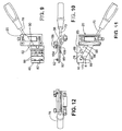
Figure 7 is a bottom perspective view showing the bottom and right side of the honing guide and with a skew chisel and a bevel setting, jig designed for use with a skew chisel secured in the guide. -
Figure 8 is a perspective view showing the top and left side of the guide, jig, and skew chisel shown inFigure 7 . -
Figure 9 is a top plan view of the guide, jig, and skew chisel shown inFigure 7 . -
Figure 10 is a right end view, looking toward the sharp end of the skew chisel, of the guide, jig, and skew chisel shown inFigure 7 . -
Figure 11 is a bottom plan view of the honing guide, bevel setting jig and the skew chisel shown inFigure 7 . -
Figure 12 is a front or end view looking toward the sharp end of the skew chisel and of the guide and jig shown inFigure 7 . -
Figure 13 is a side view in cross-section of the hollow blade clamp bar honing guide. -
Figure 14 is an enlarged view of the clamping surfaces ofFigure 14 . -
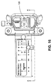
Figure 15 is a perspective view of an alternative embodiment of the honing guide of this invention having separate blade carrier and wheel frame components that can be repositioned to accommodate a wide range of bevel angles. -
Figure 16 is a top view of the alternative embodiment of the honing guide of this invention shown inFigure 15 . -
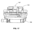
Figure 17 is a front view of the alternative embodiment of the honing guide of this invention shown inFigure 15 . -
Figure 18 is a view of right side the alternative embodiment of the honing guide of this invention shown inFigure 15 with portions of the blade carrier and wheel frame broken away to illustrate how they inter-fit. -
Figure 19 is a view of the right side of the alternative embodiment of the honing guide of this invention shown inFigure 15 with the blade carrier and wheel frame secured in a first position. -
Figure 20 is a second view likeFigure 19 with the blade carrier and wheel frame secured in a second position. -
Figure 21 is a third view likeFigure 19 with the blade carrier and wheel frame secured in a third position. -
Figure 22 is a perspective view of the top and left side of a honing guide and blade setting guide of this invention together with a pair of angle modifying wedges. -
Figure 23 is a left side view of the honing guide and bevel setting jig and wedges shown inFigure 22 . -
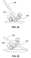
Figure 24 is a left side view of the honing guide and wedges shown inFigure 22 shown with a blade having a large bevel angle. -
Figure 25 is a left side view of the honing guide and wedges shown inFigure 22 shown with a blade having a smaller bevel angle. -
Figure 26 is a left side view of the honing guide shown inFigure 22 , with the wedges reversed and a blade shown position to hone a very small bevel angle. -
Figure 27 is a left side view of the honing guide, wedges and blade shown inFigure 26 with the blade positioned to bevel a somewhat larger bevel angle. -
Figure 28 is a fragmentary view of a wedge like those shown inFigures 22-27 showing the leaf spring in its relaxed position. -
Figure 29 is of the wedge like those shown inFigure 28 with the spring depressed by the blade securing screw or post. -
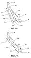
Figures 30 and 31 illustrate installation on the blade bar of a wedge of the type illustrated inFigures 22-29 . -
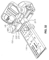
Figure 32 is a perspective view of a top and left side of a honing guide and jig, where the jig is adapted to remain attached to the honing guide during honing, and is hinged to pivot away from the abrasive surface of a sharpening stone, grinding wheel, or the like. - The chisel and plane blade honing apparatus illustrated in
Figures 1-12 includes three principal components: ablade holding guide 20 and two bevel setting jigs: a square end chisel or bladebevel setting jig 30 and a skew chisel orblade setting jig 40. As may be understood by reference toFigures 1 and2 , a tool or blade such as abench chisel 22 is secured inblade holding guide 20 with back orreference surface 24 of thechisel 22 forced against a guide reference surface, which is the underside 26 (seeFigure 7 ) ofbeam 28 ofguide body 32.Bar 34 is drawn againstchisel 22 by rotating thumb nuts 36 on threadedstuds 38.Bar 34 is adjustable both laterally and longitudinally. As may be well appreciated by reference toFigure 2 , arcuate, backward-reachingguide arms 41connect beam 28 toroller 42 that contacts anabrasive surface 44 of, for instance, a sharpeningstone 46 during use of theguide 20. These arcuate, backward-reachingarms 41 enableguide 20 to graspchisel 22 or other tools relatively close to their ends. -
Bar 34 is desirably relatively rigid so that it can be used with narrow, as well as wide, chisels 22 or other blades or tools without bending significantly. At the same time, positioning ofbar 34 near the end of thechisel 22 requires that the forward-most portion ofbar 34 be relatively thin so that it will not contactabrasive surface 44, as will be particularly well appreciated by reference toFigure 2 . Such desired rigidity with an abrasive contact-avoiding shape can be achieved by using a generally triangular cross sectional shape forbar 34, or a shape that is generally a constant thickness near thebar 34 ends and that swells to such a triangular cross-sectional shape in the middle, as is illustrated in the figures, particularly includingFigures 2 and7 . In other words, there is a leading chamfer on thebar 34. Attachment ofbar 34 withthumb nuts 36, which may be undercut, onstuds 38 positions the nuts 36 on the top of the jig, where they are easily accessible and do not prevent the desirable geometry of the underside ofguide 20. - As will also be appreciated by reference to
Figure 2 , the bevel angle that will be formed onchisel 22 during use of theguide 20 is a function of the length of chisel or plane blade projecting beyond theguide 20. Longer projection forms a shallower bevel angle. Such blade projection and proper orientation may be set by use of thebevel setting jig 30 or skewbevel setting jig 40, each of which couples to the guide during use of the settingjig guide 20 in the illustrated embodiments. - In the alternative, a
jig Figure 32 . Bevel settingjig 130 is removably attached toblade holding guide 120 by threaded posts or setscrews 218 whichsecure hinge 220 to guide 120. In this embodiment, hinge 220 allowsbevel setting jig 130 to pivot away from the abrasive surface of a sharpening stone, grinding wheel, or the like, but remain attached to guide 120, rendering the device more convenient to use. As illustrated, the lateral position ofjig 130 relative to guide 120 can be varied by looseningposts 218, slidinghinge 220 alongslots 222, and retighteningposts 218 to securejig 130 in its new position. Those of skill in the art will recognize thatjig 130 is illustrated as rigidly attached to hinge 220, and this can be obtained by welding or other appropriate method, and that equivalent functionality can be provided by locatingposts 218 andslots 222 on thejig 130 instead of, or in addition to, on theguide 120. Alternatively, the hinge can be rigidly attached to both thejig 130 and theguide 120, if adjustability or removability are not desired, e.g., to reduce manufacturing or materials costs. - In the illustrated embodiment, the
jig 30 attaches to a slidingdovetail 48 formed on thefront guide beam 28 so that thejig 30 is generally co-planer with the honingguide 20.Dovetail 48 is received in adovetail way 50 onjig body 52.Jig arms dovetail 48 by rotatingthumb screw 58 to draw thejig arms dovetail 48 structure is well adapted for temporary connection of thejigs guide 20, any other attachment structures that temporarily and properly position the jig being used with respect to the guide could be used instead. For instance, such attachment could be accomplished with one or more screws or bolts, pins in one of theguide 20 orjig - A series of parallel indicia lines 60 on
jig body 52 may be marked with various bevel angles, and ajig stop 62 may be positioned onjig body 52 in predetermined locations using a securingdevice 64. Securing device may be a knurled head thumb screw threaded intostop 62 or a spring loaded pin, either of which may be received in one ofseveral pin grooves 66 injig body 52. Other securingdevices 64 could be used, such as cam-acting clamps or any other structure that repositionably secures stop 62 in a selected desired location.Pin grooves 66 are preferably located at intervals that will position stop 62 to in turn position a chisel or blade for formingbevels 74 that form, with thereference surface 24 of the tool, angles between 20° and 40° in five degree intervals. A spring loaded ball or pin received ingrooves 66 may also be used, as may a variety of other structures for securingstop 62 at any predetermined or other desired location onjig body 52. For instance, predetermined positioning ofstop 62 could be achieved by penetratingjig body 52 with holes into which an end of securingdevice 64 is inserted to position stop 62 at the positions determined by hole locations. The location ofstop 62 may be read by reference to the stop's location along the scale formed byindicia 60. Whileindicia 60 are illustrated on the side ofjig 30, they could also be located on the top or bottom ofjig 30. - As may be best appreciated by reference to
Figures 5 and 6 , chisel 22 is positioned "square" in guide 20 (with the longitudinal axis of thetool 22 at right angles relative to the axis of roller 42) by positioning theedge 23 ofchisel 22 againstjig reference fence 25 which is "square" to theroller 42. This automatically positions the chisel orblade 22 to form anarris 72 square to the tool. Stop 62 wraps aroundfence 25, preventing removal ofstop 62 by lateral movement, and apin 27 prevents stop 62 from sliding off the end ofjig 30 by moving stop alongfence 25. Whilefence 25 is shown along one edge ofjig body 52, such afence 25 could be located on the opposite edge ofjig body 52 or at any intermediate position between those edges. The function ofreference fence 25 could also be served by other structures such as, for instance, an aligned row of pins injig body 52 so that a side of the chisel or blade can lie against two or more of such pins. Moreover, stop 62 could be omitted entirely in favor of positioning of achisel 22 or blade inguide 20 by visual reference between the position of thearris 72 and a scale or other indicia onjig body 52. - Adjacent to, and substantially parallel to,
fence 25 is groove 25A, which is adapted to receive a pin (not shown) projecting fromstop 62. This pin slidably engages groove 25A and provides a contact surface for the edge of the blade being sharpened. This prevents the blade from wedging itself between the underside ofjig 30 and the opposing surface ofstop 62. - After a principal bevel has been formed by abrading the
bevel surface 74 against an abrasive surface such asstone 46surface 44, the axis of rotation ofroller 42 may be positioned further fromback surface 24 of the chisel, thereby slightly lifting the tool orblade 22 and slightly increasing the angle of the tool orblade 22 by reference to theabrasive surface 44. This facilitates the easy formation of a micro bevel on thetool 22. Such axis of rotation movement may be accomplished, for instance, by rotatingknob 76 that is part of an eccentric mechanism described inU.S. Pat. No. 4,733,501 . - For instance, in the embodiment of the invention shown in the figures, the
roller 42 may be moved between the two positions by moving the position of theaxle 49 on which theroller 42 rotates. Theaxle 49 may be eccentrically positioned on ashaft 43 that is spring loaded to hold aknob 76 on the end of theshaft 43 against a protrusion 45 (seeFigure 7 ) on theguide body 32 in one of at least twodetents 47 inknob 76. Theknob 76 is pulled axially to overcome the spring (not shown but positioned around the exposed portion ofshaft 43 betweenroller 42 and protrusion 45) and disengage thedetent 47 fromprotrusion 45 and rotated to engage anotherdetent 47. - Honing
guide 20 may also be used as a grinding jig. Structure behind theroller 42, such as a protrudingledge 21 easily seen inFigures 1 and2 , enables theguide 20 to rest on a tool rest on a typical motorized bench grinder, belt grinder or other motorized abrasive device. This will allow the user to position a tool such aschisel 22 to be sharpened once in the guide for both rough grinding and fine honing. -
Figures 7-12 illustrate use ofguide 20 with askew chisel 70. Positioning of askew chisel 70 in the honingguide 20 can be facilitated by contact between achisel side 78 and areference face 81 of areference block 85 positioned onskew setting jig 40 and with the skewchisel cutting arris 172 contacting areference pin 80 on the end of aknurled head thumbscrew 82. - The reference faces 81 and 83 of
reference block 85 form the same angle "a" withbase side 86 ofblock 85 aslonger side 78 ofskew chisel 70 forms witharris 172. A "right hand" skew is positioned on one side of theblock 85 and a "left hand" skew is positioned for sharpening on the other side ofblock 85. For skew chisels having an arris at a different angle, adifferent block 85 with different angles "a" will be needed.Block 85 can be removably attached using appropriate fasteners such as screws (not shown), permitting use of interchangeable blocks for skews with different angles. Preferably, however, block 85 will be formed as a part of skew-settingjig 40, which is feasible because most skew chisels have the same angle (60°). As in settingjig 30 described above,arms jig 40 tighten against opposite sides ofdovetail 48 in order temporarily to positionjig 40 onguide 20 during positioning ofskew chisel 70 inguide 20, but, as described above, any suitable alternative method of attachment could instead be used. - As may be understood by reference to
Figures 7-12 ,skew jig 40 is penetrated byholes 88 within whichreference screw 82 may be alternatively positioned in order to positionpin 80 at predetermined locations that will result (when used together with block 85) inpositioning skew chisel 70 to form abevel 174 at a desired predetermined angle. Such apositioning pin 80 and holes 88 are a well-functioning stop structure for theskew jig 40 because the optimal stop positions do not lie along an edge of thejig 40, as may be done in the square-tool jig 40. Similar to the observation above aboutjig 30, other stop structures would also be used, however, injig 40, and the stops could be entirely omitted in favor of visual reference between askew chisel 70 and angle indicia on thejig 40. - Indicia 90 (see
Figures 1 ,3 and9 ) on thebody 32 ofguide 20 are used by reference to asmall mark 91 onjig 30. When using theguide 20 andjig 30, it will be necessary to secure thejig 30 in an appropriate position before thechisel 22 or other tool to be honed is clamped in place. Since it is desirable for thechisel 22 or other tool to be honed to be clamped so it is centered betweenarms 41 of theguide 20, it is necessary to know in advance where thejig 30 should be fixed on slidingdovetail 48 such that the resultant tool position is centered. The reference mark is to be aligned with thescale increment 90 to correspond to the width (in Metric measurements or inches, for instance) of thechisel 22 or other tool, to be honed. Indicia 92 (seeFigures 8 and9 ) onjig 30 are used by reference to either one of two specially shaped reference marks within thescale 90 onguide 20 depending on whether the skew chisel to be sharpened is "left hand "or "right hand" and depending on the width of the skew, which will typically be one of three common widths, 12.7 mm (1/2"), 19.1 mm (3/4") or 25.4 mm (1"). This will ensure that theskew 70 is optimally positioned to achieve the best possible relative orientation betweenroller 42 and cuttingarris 172.Indicia 92 may be laser etched or formed in some other appropriate manner making the indicia clearly visible to the user during set up. - As will be appreciated by those familiar with tool manufacture, the
guide body 32 andbar 34 can be made by die casting. Components so formed can then be anodized to form an attractive and wear-resistant surface. Components of this invention can also be manufactured of other materials and utilizing other manufacturing techniques. For instance, components could be machined from steel, brass (particularly in the case of the screws), or aluminum bar stock or could be molded of suitable plastic or plastic composite materials or produced by zinc die-casting. - As will be appreciated by those skilled in the art, this invention can be practiced in numerous alternative embodiments in addition to those shown in the drawings and described above without departing from the scope of this invention as defined by the following claims.
- For instance, one or more wheels could be used rather than the illustrated roller, and other structures could be used for shifting the axis of rotation of the roller in order to form micro bevels, or such structure could be omitted entirely if its micro bevel forming function were not desired. A jig in accordance with this invention could also be structured for contact between the
roller 42 and reference structure other than theabrasive surface 44. For instance,roller 42 could be arranged to contact bench-top or other planar surface on which the abrasive 46 rests, as is done in some prior art honing guides. -
Figures 13 and 14 illustrate a honingguide 100 havingclamp bars 102 between which atool 104 is clamped in place for honing or sharpening. Theconcave clamping surface 106 of thebars 102 force regions ofcontact 108 between thetool 104 and thesurface 106 as far apart as possible, so that the clamping force is concentrated along parallel lines at the edges of thebars 102. - Another possible variation of the blade honing guide of this invention involves utilization of structures that change the range of bevel angles possible. This can be accomplished by changing the positions of the wheel or roller axes of rotation relative to the blade securing structure (as is done in the micro-bevel structure described above, but by greater amounts). This can also be done by changing the angular position of the blade being held by the guide, as for instance changing the planes of the surfaces that clamp the blade.
- An alternative embodiment of this invention having provision for an increased range of bevel angles by making the blade carrier and wheel frame separate components is illustrated in
Figures 15-19 . - As is shown in
Figure 15 , aguide 120 may be attached to abevel setting jig 130, and these components function generally as described above by reference to theguide 20 andbevel setting jig 30. As is well illustrated byFigure 18 , theguide 20 has a guide body 132 provided by ablade carrier 131 and awheel frame 133.Carrier 131 is secured towheel frame 133 with a screw or stud (not shown) that passes through aslot 135 incarrier 131 and intowheel frame 133 and is tightened by rotating head orcap 137.Carrier 131 andframe 133 may be moved relative to each other and secured to each other in multiple positions. Such positioning could be in any relative location within a range of motion possible; however, it is preferable that an arrangement of detents, stops or other structure be provided so that relative positioning can be in repeatable locations. Such structure is provided in theguide 120 shown in the figures by the provision of aprotruding ridge 139 onframe 133 that is alternatively received in one of threetroughs carrier 131. Configuration of theguide 120 with the protrudingridge 139 positioned alternatively in each oftroughs Figures 19 ,20 and21 . As will be readily appreciated by reference to the Figures, particularly includingFigures 19 ,20 and21 , the different relative configurations ofcarrier 131 andframe 133 permit a wide range of bevel angles to be honed on blades and chisels secured in theguide 120. The joint betweencarrier 131 andframe 133 can be configured in three positions to allow three angle ranges, low angles (10° to 15°), mid range angles (15° to 40°) and high angles (25° to 65°). - Other structures than those illustrated in the Figures and described above can be used to join
carrier 131 andframe 133. The mating surfaces of these components can have matching protrusions and recesses having many different structures or can utilize entirely different structures such as a sliding dovetail or other adjustable, interfitting structure and appropriate locking mechanism, including arrangements allowing pivoting attachment of thecarrier 131 to theframe 133. Any structure may be used provided that it provides for securely and, preferably, repeatably attaching thecarrier 131 to theframe 133 in a range of locations or in multiple locations, including more or less than three locations. - Furthermore, a wheel need not be the only structure used for contact with the abrasive stone or other reference surface. A low friction pad, a rail system, or another appropriate guiding system could all be used / all be suitable.
- The angular position of the blade or chisel being honed in the blade carrier portion of the honing guide of this invention can be modified by placing the blade or chisel between an opposed pair of matching wedges within the blade clamping structure.
Figures 22-31 illustrate use ofsuch wedges 200 with theguide 20 andbevel setting jig 30 of this invention, butsuch wedges 200 could be used with other honing guides. -
Wedges 200 are shown installed inguide 20 inFigures 24-27 , but their structure and installation can be best understood by reference toFigures 28-31 . Eachwedge 200 is an elongated body having a wedge-shaped cross section with an included angle of approximately 16 (other included angles are also usable). One end of thewedge 200 has anopen slot 202 that receives onestud 38 attached to bar 34, and the other end has an L-shaped recess that receives theother stud 38 ofbar 34. Abent leaf spring 206 attaches to wedge 200 adjacent to and extends intorecess 204 so that (as is well illustrated byFigures 30 and 31 )positioning wedge 200 onbar 34 causes depression ofspring 206 by thestud 38 received in thatrecess 204 securing thewedge 200 in position and resisting its dislocation. As will be appreciated by reference to the Figures, securing a blade (e.g.,blade 208 inFigures 24 and 25 ) will exert pressure on thewedges 200 causing it to tend to slide relative to and off thebar 34 orbeam 28. The location ofprotrusions wedge 200 so that they contactstuds 38 preventswedge 200 from being dislocated. - Alternative end structures could be used on
wedges 200 for positioning and retaining them on the honing guide. For instance, the ends of thewedges 200 could be penetrated by round holes for receiving thestuds 38. Assembly ofsuch wedges 200 and the honing guide would require removal of thebar 34 from the guide to position the wedges on the studs. - A
recess 214 in the faces of thewedge 200 ensures that the blade or honing guide structure as may be the case contacts the wedge near its edges.Similar recesses 216 may be used in the face of thebar 34.
Claims (22)
- A honing guide (20, 120) and bevel setting jig (30, 40, 130) for honing a tool or blade (22, 70);
the guide comprising a holder (32, 131) for the tool or blade and a guiding system (41, 42, 133) for the holder which contacts a reference surface in use,
the jig being adapted for coupling to the guide
and comprising a stop or indicium (25, 60, 62, 80, 83, 90, 92) to facilitate positioning the tool or blade in the holder to form a bevel at a predetermined angle,
characterised in that the jig is tightly securable to the guide when positioning the tool or blade in the holder, to facilitate positioning of the tool or blade against the stop or indicium. - The honing guide and bevel setting jig of claim 1, wherein the tool or blade (22, 70) is secured in the guide (20, 120) by drawing a securing bar (34) toward a guide reference surface (26) to capture the tool or blade between the bar and the guide reference surface, at least a central portion of the securing bar having a generally triangular cross sectional shape.
- The honing guide and bevel setting jig of claim 2, wherein the shape of the securing bar (34) swells from relatively constant thickness proximate its ends to a central portion having the generally triangular cross sectional shape.
- The honing guide and bevel setting jig of any preceding claim, wherein the jig (30, 40, 130) is adapted to be tightly coupled to the guide (20, 120) in multiple positions, and further comprising indicia (90, 92) on at least one of the guide or jig to facilitate desirable positioning of the jig when coupling the jig to the guide so that the tool or blade (22, 70) will be desirably positioned in the guide.
- The honing guide and bevel setting jig of any preceding claim wherein the jig (30, 40, 130) is adapted to be tightly coupled to the guide (20, 120) in multiple relative lateral positions.
- The honing guide and bevel setting jig of any preceding claim in which the jig (30, 40, 130) is adapted to be tightly coupled to the guide (20, 120) by a pair of arms drawable towards each other by a screw.
- The honing guide and bevel setting jig of any of claims 1 - 7 wherein the jig .(30, 40, 130) is tightly coupled to the guide (20, 120) by a connection comprising one or more of a pin-and-hole, screws, bolts and a tongue-and groove.
- The tool honing guide and bevel setting jig of any preceding claim, further comprising a hinge disposed between the honing guide (20, 120) and bevel setting jig (30, 40, 130) and attached to each, adapted to pivot the bevel setting jig away from an abrasive surface.
- The honing guide and bevel setting jig of any preceding claim, wherein the jig (30, 40, 130) is releasably attachable to the guide (20, 120) by clamping the jig against a dovetail structure on the guide.
- The honing guide and bevel setting jig of any preceding claim, further comprising a repositionable stop (62, 80) for establishing projection of the tool or blade (22, 70) from the guide (20, 120).
- The honing guide and bevel setting jig of any preceding claim, further comprising a rest (21) for engaging a motorized grinder tool rest while contacting an abrasive surface of the grinder with the tool or blade (22, 70).
- The honing guide and bevel setting jig of any preceding claim, further comprising concave surface clamping bars (102).
- The honing guide and bevel setting jig of any preceding claim, wherein the guiding system comprises a frame (133) repositionably attachable to the tool or blade holder (131) so that the guiding system can be attached to the tool or blade holder in more than one position during use of the guide (20, 120).
- The honing guide and bevel setting jig of claim 13, wherein one of the tool / blade holder (131) or frame (133) has at least one ridge (139) for receipt in at least one matching trough (141, 143, 145) in the other of the frame or the tool / blade holder.
- The honing guide and bevel setting jig of claim 14, wherein the tool or blade holder (131) and frame (133) are attachable in three different relative positions.
- The honing guide and bevel setting jig of any preceding claim, further comprising a pair of wedges (200), one of which is positioned in use between a top face of the tool or blade (22, 70) and the holder (32, 131) and the other of which is positioned in use between a bottom face of the tool or blade and the holder, to change the angle between the tool or blade and the holder.
- The honing guide and bevel setting jig of claim 16, wherein the tool or blade holder (32, 131) has two studs (38) for securing the tool or blade in the holder, and wherein each wedge has two ends and an opening (202, 206) near each end for receiving one of the two studs.
- The honing guide and bevel setting jig of claim 16 or 17, wherein the included angle of each wedge (200) is approximately 16 degrees.
- The honing guide and bevel setting jig of any preceding claim, wherein the jig (30, 40, 130) has at least one positioning surface (25, 81, 83) for contact with a side of the tool or blade (22, 70) during positioning of the tool or blade in the jig.
- The honing guide and bevel setting jig of claim 19, wherein the positioning surface (81, 83) is not square to the setting jig (40) for positioning a skew end tool or blade (22, 70) in the guide (20, 120).
- The honing guide and bevel setting jig of any of claims 1 - 19, wherein the stop or indicium on the jig (30, 130) is for positioning a square edge tool or blade (22) and further comprising a second jig (40) adapted for removable coupling to the guide (20, 120) to facilitate positioning a second tool or blade in the guide to fonn a bevel on a skew edge (172) thereof, the second jig comprising:a. two skewed positioning surfaces (81, 83) for contact with a side (78) of the second, skew edge tool or blade (70), andb. a repositionable stop (80) for establishing projection of the second tool from the guide.
- A method of sharpening a tool or blade (22, 70), comprising:(a) positioning the tool or blade in a honing guide (20, 120) having a holder (32, 131) for the tool or blade (22, 70) and a guiding system (41, 42, 133) for the holder which contacts a reference surface in use, the positioning of the tool or blade comprising:(i) positioning the tool or blade against a stop or indicium (25, 60, 62, 80, 83, 90, 92) on a bevel setting jig (30, 40, 130) coupled to the guide, (ii) securing the tool or blade in the holder;(b) removing the stop or indicium from against the tool or blade,(c) manipulating the honing guide and tool or blade to abrade the tool or blade against an abrasive while maintaining contact between the guiding system and a reference surface; characterised in that in step (a) (i) the bevel setting jig is tightly secured to the guide, to facilitate positioning of the tool or blade against the stop or indicium.
Applications Claiming Priority (3)
| Application Number | Priority Date | Filing Date | Title |
|---|---|---|---|
| US46348403P | 2003-04-17 | 2003-04-17 | |
| US50959903P | 2003-10-08 | 2003-10-08 | |
| PCT/IB2004/001152 WO2004091860A2 (en) | 2003-04-17 | 2004-04-16 | Honing guide assembly |
Publications (2)
| Publication Number | Publication Date |
|---|---|
| EP1624995A2 EP1624995A2 (en) | 2006-02-15 |
| EP1624995B1 true EP1624995B1 (en) | 2012-02-15 |
Family
ID=33303123
Family Applications (1)
| Application Number | Title | Priority Date | Filing Date |
|---|---|---|---|
| EP04727955A Expired - Lifetime EP1624995B1 (en) | 2003-04-17 | 2004-04-16 | Honing guide assembly |
Country Status (7)
| Country | Link |
|---|---|
| US (1) | US7553216B2 (en) |
| EP (1) | EP1624995B1 (en) |
| CN (1) | CN1795077B (en) |
| AT (1) | ATE545486T1 (en) |
| AU (1) | AU2004230315B2 (en) |
| CA (1) | CA2518450C (en) |
| WO (1) | WO2004091860A2 (en) |
Families Citing this family (25)
| Publication number | Priority date | Publication date | Assignee | Title |
|---|---|---|---|---|
| US7666067B2 (en) * | 2004-06-11 | 2010-02-23 | Tj Utveckling Ab | Method and device for sharpening a cutting tool |
| US7056195B2 (en) | 2004-09-16 | 2006-06-06 | Geoffrey John Hamilton Evans | Apparatus and method for sharpening tool blades |
| US7281969B2 (en) * | 2005-05-11 | 2007-10-16 | Donald Naples | Tool sharpening and compound honing jig |
| USD611513S1 (en) | 2005-10-17 | 2010-03-09 | Lee Valley Tools, Ltd. | File and rasp grip |
| SE529606C2 (en) * | 2006-02-10 | 2007-10-02 | Tj Utveckling Ab | Tool adjuster for a grinding machine |
| WO2007124466A2 (en) * | 2006-04-20 | 2007-11-01 | Swartz Ronald F | Self-aligning honing device |
| US8388413B1 (en) * | 2008-09-19 | 2013-03-05 | Darex, Llc | Wideblade sharpening guide |
| GB2482332A (en) * | 2010-07-30 | 2012-02-01 | Elixair Internat Ltd | Automatic Portable Sharpening Apparatus with Tool Guide |
| US9289874B1 (en) * | 2012-05-03 | 2016-03-22 | Daniel B. Sabo | Modular honing guide system |
| CN103722252A (en) * | 2012-10-11 | 2014-04-16 | 天太·郭元焜 | Manual planer gear grinding machine |
| US9033771B2 (en) * | 2013-02-22 | 2015-05-19 | Lifetime Brands, Inc. | Knife sharpener |
| US9908211B2 (en) * | 2013-09-06 | 2018-03-06 | The Boeing Company | Tool support |
| US9168640B2 (en) * | 2013-11-20 | 2015-10-27 | Harrelson Stanley | Holder for sharpening and faceting |
| US9221144B2 (en) | 2013-12-23 | 2015-12-29 | David G. Powell | Universal sharpening jig for a cutting blade |
| US9962806B2 (en) * | 2014-09-12 | 2018-05-08 | The Shop, Inc. | Blade sharpening devices, blade sharpening systems and methods of sharpening a blade |
| TWD171425S (en) * | 2014-10-31 | 2015-11-01 | 黃振華 | Part of woodworking special drilling mold fixture |
| SE539239C2 (en) * | 2015-02-18 | 2017-05-23 | Tormek Ab | Adjustable grinding jig |
| USD767360S1 (en) | 2015-05-12 | 2016-09-27 | Lee Valley Tools Ltd. | Chisel honing guide blade carrier |
| US10759017B2 (en) * | 2018-03-23 | 2020-09-01 | David G. Powell | Glideway crowning plate and method thereof for creating a crown on a cutting edge of a cutting blade with a sharpening jig |
| KR102056029B1 (en) * | 2019-08-13 | 2019-12-13 | 김탄욱 | Honing Guide |
| US10744619B1 (en) * | 2019-09-17 | 2020-08-18 | Oleg Boutorine | Compact angle reference apparatus for sharpening blades |
| CN111922897B (en) * | 2020-09-29 | 2020-12-29 | 常州凯瑞莱精密工具有限公司 | Axial displacement adjustable chuck of honing tool |
| USD990275S1 (en) * | 2021-03-30 | 2023-06-27 | Choon's Kitchenware, LLC | Blade sharpening device |
| USD990274S1 (en) * | 2021-03-30 | 2023-06-27 | Choon's Kitchenware, LLC | Blade sharpening device |
| CN115338773B (en) * | 2022-07-29 | 2023-09-29 | 中国第一汽车股份有限公司 | Cylinder hole honing and aligning device and method |
Family Cites Families (27)
| Publication number | Priority date | Publication date | Assignee | Title |
|---|---|---|---|---|
| US560111A (en) * | 1896-05-12 | Tool-holder | ||
| US449673A (en) * | 1891-04-07 | Holder for gravers while being ground | ||
| US418781A (en) | 1890-01-07 | Device for holding tools for grinding | ||
| US364353A (en) * | 1887-06-07 | Eichaed kampfe | ||
| US210957A (en) * | 1878-12-17 | Improvement in portable tool-rests | ||
| US166830A (en) * | 1875-08-17 | Improvement in sharpening-machines | ||
| US729319A (en) * | 1902-12-27 | 1903-05-26 | Walter Baker Fowler | Tool-holding device. |
| US1239494A (en) * | 1917-01-15 | 1917-09-11 | Hugo A Lange | Graver-sharpener. |
| US1498283A (en) * | 1922-05-31 | 1924-06-17 | William A Kelsey | Dental tool holder |
| GB215818A (en) | 1923-02-10 | 1924-05-12 | Edward Lawrence Chadwick | Improvements in and connected with devices for sharpening chisels, plane blades and the like |
| US1770538A (en) * | 1928-01-25 | 1930-07-15 | Horace J Warner | Support for blade holders |
| GB326370A (en) | 1929-04-03 | 1930-03-13 | Franz Wobst | Improvements in work holders for use in grinding plane irons and other cutting tools |
| DE526996C (en) * | 1930-10-18 | 1931-06-12 | Konrad Stichel | Device for grinding curved cutting edges on knife blades for woodworking |
| US2353096A (en) * | 1941-09-18 | 1944-07-04 | Samuel Briskman | Work holder |
| GB626372A (en) | 1947-01-27 | 1949-07-14 | Dudley Austic Layton | Improvements in or relating to devices for facilitating the sharpening of chisels, plane blades and the like |
| GB693863A (en) | 1951-04-30 | 1953-07-08 | Costas Vaffiadis | Improvements relating to means for facilitating the grinding or honing of plane irons, chisels and the like |
| US2740241A (en) * | 1955-01-07 | 1956-04-03 | Cristo Z Mccubbin | Tool holders |
| GB795157A (en) | 1956-03-03 | 1958-05-14 | C & J Hampton Ltd | Improvements in or relating to honing clamps for plane irons and the like |
| FR1205686A (en) | 1958-07-16 | 1960-02-04 | Adjustable tool holder for sharpening plane irons, blades or other tools | |
| GB911900A (en) | 1960-11-02 | 1962-11-28 | Kenneth Barton Cox | A holder for use in the sharpening of the blades of tools |
| GB924579A (en) | 1961-04-18 | 1963-04-24 | Neill James & Co Sheffield Ltd | Improvements in or relating to honing clamps for chisels and the like |
| GB1445422A (en) * | 1973-06-01 | 1976-08-11 | Stanley Tools Ltd | Blade holder for use when sharpening and/or honing |
| US4078781A (en) * | 1976-12-07 | 1978-03-14 | Hmc-Brauer Limited | Clamps |
| US4733501A (en) * | 1985-09-23 | 1988-03-29 | Lee Valley Tools Ltd. | Honing guide |
| JP4025831B2 (en) * | 1996-08-07 | 2007-12-26 | 斉藤 悦朗 | Blade polishing equipment |
| US6726551B2 (en) * | 2001-01-11 | 2004-04-27 | Edgecraft Corporation | Manual knife sharpener with angle control |
| CN2477318Y (en) * | 2001-04-17 | 2002-02-20 | 李东仁 | Drill grinder |
-
2004
- 2004-04-16 US US10/553,592 patent/US7553216B2/en not_active Expired - Lifetime
- 2004-04-16 CA CA2518450A patent/CA2518450C/en not_active Expired - Fee Related
- 2004-04-16 AT AT04727955T patent/ATE545486T1/en active
- 2004-04-16 EP EP04727955A patent/EP1624995B1/en not_active Expired - Lifetime
- 2004-04-16 CN CN2004800101191A patent/CN1795077B/en not_active Expired - Fee Related
- 2004-04-16 WO PCT/IB2004/001152 patent/WO2004091860A2/en not_active Ceased
- 2004-04-16 AU AU2004230315A patent/AU2004230315B2/en not_active Ceased
Also Published As
| Publication number | Publication date |
|---|---|
| WO2004091860A2 (en) | 2004-10-28 |
| CA2518450A1 (en) | 2004-10-28 |
| WO2004091860A3 (en) | 2005-03-10 |
| AU2004230315B2 (en) | 2010-06-03 |
| CA2518450C (en) | 2011-01-25 |
| US7553216B2 (en) | 2009-06-30 |
| ATE545486T1 (en) | 2012-03-15 |
| AU2004230315A1 (en) | 2004-10-28 |
| CN1795077A (en) | 2006-06-28 |
| HK1085423A1 (en) | 2006-08-25 |
| CN1795077B (en) | 2012-02-15 |
| EP1624995A2 (en) | 2006-02-15 |
| US20060211348A1 (en) | 2006-09-21 |
Similar Documents
| Publication | Publication Date | Title |
|---|---|---|
| CA2518450C (en) | Honing guide assembly | |
| US20070281594A1 (en) | Honing guide assembly with camber roller | |
| US11883930B2 (en) | Precision adjust sharpener | |
| US11685010B2 (en) | Adjustable sharpening apparatus and method for cutting implements | |
| US7549910B2 (en) | Blade sharpening holder | |
| US8197304B2 (en) | Method and apparatus for sharpening a tool blade | |
| US10131028B1 (en) | Adjustable sharpening apparatus and method for cutting implements | |
| US11052512B1 (en) | Adjustable knife sharpener and clamping assembly | |
| US7281969B2 (en) | Tool sharpening and compound honing jig | |
| US6227958B1 (en) | Knife and sharpening holder | |
| EP1818138A1 (en) | A tool setter for a grinding machine | |
| US6926596B1 (en) | Tool sharpening apparatus | |
| CA1200105A (en) | Portable chain saw sharpening kit with cutting link alignment means and method for using same | |
| US7335093B1 (en) | Blade sharpening holder | |
| HK1085423B (en) | Honing guide assembly | |
| US4338749A (en) | Toolholder | |
| CA2228943A1 (en) | Apparatus for sharpening/bevelling of ski or snowboard edges | |
| US6405615B1 (en) | Fixture for snowboard edge finishing tool | |
| US5643066A (en) | Fixture for ski edge finishing tool | |
| CA2619791C (en) | Blade sharpening holder | |
| CN222059705U (en) | Grinding assembly and sharpener including the same | |
| US20050239384A1 (en) | Reshaping fixture for carbide inserts | |
| HK1093036A (en) | Honing guide assembly | |
| GB2397788A (en) | Honing guide for tool sharpening |
Legal Events
| Date | Code | Title | Description |
|---|---|---|---|
| PUAI | Public reference made under article 153(3) epc to a published international application that has entered the european phase |
Free format text: ORIGINAL CODE: 0009012 |
|
| 17P | Request for examination filed |
Effective date: 20051116 |
|
| AK | Designated contracting states |
Kind code of ref document: A2 Designated state(s): AT BE BG CH CY CZ DE DK EE ES FI FR GB GR HU IE IT LI LU MC NL PL PT RO SE SI SK TR |
|
| DAX | Request for extension of the european patent (deleted) | ||
| RAP1 | Party data changed (applicant data changed or rights of an application transferred) |
Owner name: LEE VALLEY TOOLS LTD. |
|
| REG | Reference to a national code |
Ref country code: HK Ref legal event code: DE Ref document number: 1085423 Country of ref document: HK |
|
| 17Q | First examination report despatched |
Effective date: 20110222 |
|
| 17Q | First examination report despatched |
Effective date: 20110222 |
|
| GRAP | Despatch of communication of intention to grant a patent |
Free format text: ORIGINAL CODE: EPIDOSNIGR1 |
|
| GRAS | Grant fee paid |
Free format text: ORIGINAL CODE: EPIDOSNIGR3 |
|
| GRAA | (expected) grant |
Free format text: ORIGINAL CODE: 0009210 |
|
| AK | Designated contracting states |
Kind code of ref document: B1 Designated state(s): AT BE BG CH CY CZ DE DK EE ES FI FR GB GR HU IE IT LI LU MC NL PL PT RO SE SI SK TR |
|
| REG | Reference to a national code |
Ref country code: GB Ref legal event code: FG4D Ref country code: CH Ref legal event code: EP |
|
| REG | Reference to a national code |
Ref country code: IE Ref legal event code: FG4D |
|
| REG | Reference to a national code |
Ref country code: AT Ref legal event code: REF Ref document number: 545486 Country of ref document: AT Kind code of ref document: T Effective date: 20120315 |
|
| REG | Reference to a national code |
Ref country code: DE Ref legal event code: R096 Ref document number: 602004036513 Country of ref document: DE Effective date: 20120412 |
|
| REG | Reference to a national code |
Ref country code: NL Ref legal event code: VDEP Effective date: 20120215 |
|
| PG25 | Lapsed in a contracting state [announced via postgrant information from national office to epo] |
Ref country code: NL Free format text: LAPSE BECAUSE OF FAILURE TO SUBMIT A TRANSLATION OF THE DESCRIPTION OR TO PAY THE FEE WITHIN THE PRESCRIBED TIME-LIMIT Effective date: 20120215 |
|
| PG25 | Lapsed in a contracting state [announced via postgrant information from national office to epo] |
Ref country code: GR Free format text: LAPSE BECAUSE OF FAILURE TO SUBMIT A TRANSLATION OF THE DESCRIPTION OR TO PAY THE FEE WITHIN THE PRESCRIBED TIME-LIMIT Effective date: 20120516 Ref country code: PL Free format text: LAPSE BECAUSE OF FAILURE TO SUBMIT A TRANSLATION OF THE DESCRIPTION OR TO PAY THE FEE WITHIN THE PRESCRIBED TIME-LIMIT Effective date: 20120215 Ref country code: PT Free format text: LAPSE BECAUSE OF FAILURE TO SUBMIT A TRANSLATION OF THE DESCRIPTION OR TO PAY THE FEE WITHIN THE PRESCRIBED TIME-LIMIT Effective date: 20120615 Ref country code: FI Free format text: LAPSE BECAUSE OF FAILURE TO SUBMIT A TRANSLATION OF THE DESCRIPTION OR TO PAY THE FEE WITHIN THE PRESCRIBED TIME-LIMIT Effective date: 20120215 Ref country code: BE Free format text: LAPSE BECAUSE OF FAILURE TO SUBMIT A TRANSLATION OF THE DESCRIPTION OR TO PAY THE FEE WITHIN THE PRESCRIBED TIME-LIMIT Effective date: 20120215 |
|
| REG | Reference to a national code |
Ref country code: HK Ref legal event code: GR Ref document number: 1085423 Country of ref document: HK |
|
| REG | Reference to a national code |
Ref country code: AT Ref legal event code: MK05 Ref document number: 545486 Country of ref document: AT Kind code of ref document: T Effective date: 20120215 |
|
| PG25 | Lapsed in a contracting state [announced via postgrant information from national office to epo] |
Ref country code: CY Free format text: LAPSE BECAUSE OF FAILURE TO SUBMIT A TRANSLATION OF THE DESCRIPTION OR TO PAY THE FEE WITHIN THE PRESCRIBED TIME-LIMIT Effective date: 20120215 |
|
| PG25 | Lapsed in a contracting state [announced via postgrant information from national office to epo] |
Ref country code: CZ Free format text: LAPSE BECAUSE OF FAILURE TO SUBMIT A TRANSLATION OF THE DESCRIPTION OR TO PAY THE FEE WITHIN THE PRESCRIBED TIME-LIMIT Effective date: 20120215 Ref country code: SI Free format text: LAPSE BECAUSE OF FAILURE TO SUBMIT A TRANSLATION OF THE DESCRIPTION OR TO PAY THE FEE WITHIN THE PRESCRIBED TIME-LIMIT Effective date: 20120215 Ref country code: SE Free format text: LAPSE BECAUSE OF FAILURE TO SUBMIT A TRANSLATION OF THE DESCRIPTION OR TO PAY THE FEE WITHIN THE PRESCRIBED TIME-LIMIT Effective date: 20120215 Ref country code: DK Free format text: LAPSE BECAUSE OF FAILURE TO SUBMIT A TRANSLATION OF THE DESCRIPTION OR TO PAY THE FEE WITHIN THE PRESCRIBED TIME-LIMIT Effective date: 20120215 Ref country code: RO Free format text: LAPSE BECAUSE OF FAILURE TO SUBMIT A TRANSLATION OF THE DESCRIPTION OR TO PAY THE FEE WITHIN THE PRESCRIBED TIME-LIMIT Effective date: 20120215 Ref country code: EE Free format text: LAPSE BECAUSE OF FAILURE TO SUBMIT A TRANSLATION OF THE DESCRIPTION OR TO PAY THE FEE WITHIN THE PRESCRIBED TIME-LIMIT Effective date: 20120215 |
|
| PG25 | Lapsed in a contracting state [announced via postgrant information from national office to epo] |
Ref country code: SK Free format text: LAPSE BECAUSE OF FAILURE TO SUBMIT A TRANSLATION OF THE DESCRIPTION OR TO PAY THE FEE WITHIN THE PRESCRIBED TIME-LIMIT Effective date: 20120215 Ref country code: IT Free format text: LAPSE BECAUSE OF FAILURE TO SUBMIT A TRANSLATION OF THE DESCRIPTION OR TO PAY THE FEE WITHIN THE PRESCRIBED TIME-LIMIT Effective date: 20120215 Ref country code: MC Free format text: LAPSE BECAUSE OF NON-PAYMENT OF DUE FEES Effective date: 20120430 |
|
| REG | Reference to a national code |
Ref country code: CH Ref legal event code: PL |
|
| PLBE | No opposition filed within time limit |
Free format text: ORIGINAL CODE: 0009261 |
|
| STAA | Information on the status of an ep patent application or granted ep patent |
Free format text: STATUS: NO OPPOSITION FILED WITHIN TIME LIMIT |
|
| REG | Reference to a national code |
Ref country code: IE Ref legal event code: MM4A |
|
| REG | Reference to a national code |
Ref country code: FR Ref legal event code: ST Effective date: 20121228 |
|
| 26N | No opposition filed |
Effective date: 20121116 |
|
| PG25 | Lapsed in a contracting state [announced via postgrant information from national office to epo] |
Ref country code: CH Free format text: LAPSE BECAUSE OF NON-PAYMENT OF DUE FEES Effective date: 20120430 Ref country code: LI Free format text: LAPSE BECAUSE OF NON-PAYMENT OF DUE FEES Effective date: 20120430 Ref country code: IE Free format text: LAPSE BECAUSE OF NON-PAYMENT OF DUE FEES Effective date: 20120416 Ref country code: AT Free format text: LAPSE BECAUSE OF FAILURE TO SUBMIT A TRANSLATION OF THE DESCRIPTION OR TO PAY THE FEE WITHIN THE PRESCRIBED TIME-LIMIT Effective date: 20120215 |
|
| PG25 | Lapsed in a contracting state [announced via postgrant information from national office to epo] |
Ref country code: FR Free format text: LAPSE BECAUSE OF NON-PAYMENT OF DUE FEES Effective date: 20120430 |
|
| REG | Reference to a national code |
Ref country code: DE Ref legal event code: R097 Ref document number: 602004036513 Country of ref document: DE Effective date: 20121116 |
|
| PG25 | Lapsed in a contracting state [announced via postgrant information from national office to epo] |
Ref country code: ES Free format text: LAPSE BECAUSE OF FAILURE TO SUBMIT A TRANSLATION OF THE DESCRIPTION OR TO PAY THE FEE WITHIN THE PRESCRIBED TIME-LIMIT Effective date: 20120526 |
|
| PG25 | Lapsed in a contracting state [announced via postgrant information from national office to epo] |
Ref country code: BG Free format text: LAPSE BECAUSE OF FAILURE TO SUBMIT A TRANSLATION OF THE DESCRIPTION OR TO PAY THE FEE WITHIN THE PRESCRIBED TIME-LIMIT Effective date: 20120515 |
|
| PG25 | Lapsed in a contracting state [announced via postgrant information from national office to epo] |
Ref country code: TR Free format text: LAPSE BECAUSE OF FAILURE TO SUBMIT A TRANSLATION OF THE DESCRIPTION OR TO PAY THE FEE WITHIN THE PRESCRIBED TIME-LIMIT Effective date: 20120215 |
|
| PG25 | Lapsed in a contracting state [announced via postgrant information from national office to epo] |
Ref country code: LU Free format text: LAPSE BECAUSE OF NON-PAYMENT OF DUE FEES Effective date: 20120416 |
|
| PG25 | Lapsed in a contracting state [announced via postgrant information from national office to epo] |
Ref country code: HU Free format text: LAPSE BECAUSE OF FAILURE TO SUBMIT A TRANSLATION OF THE DESCRIPTION OR TO PAY THE FEE WITHIN THE PRESCRIBED TIME-LIMIT Effective date: 20040416 |
|
| PGFP | Annual fee paid to national office [announced via postgrant information from national office to epo] |
Ref country code: DE Payment date: 20180420 Year of fee payment: 15 |
|
| REG | Reference to a national code |
Ref country code: DE Ref legal event code: R119 Ref document number: 602004036513 Country of ref document: DE |
|
| PG25 | Lapsed in a contracting state [announced via postgrant information from national office to epo] |
Ref country code: DE Free format text: LAPSE BECAUSE OF NON-PAYMENT OF DUE FEES Effective date: 20191101 |
|
| PGFP | Annual fee paid to national office [announced via postgrant information from national office to epo] |
Ref country code: GB Payment date: 20230223 Year of fee payment: 20 |
|
| REG | Reference to a national code |
Ref country code: GB Ref legal event code: PE20 Expiry date: 20240415 |
|
| PG25 | Lapsed in a contracting state [announced via postgrant information from national office to epo] |
Ref country code: GB Free format text: LAPSE BECAUSE OF EXPIRATION OF PROTECTION Effective date: 20240415 |
|
| PG25 | Lapsed in a contracting state [announced via postgrant information from national office to epo] |
Ref country code: GB Free format text: LAPSE BECAUSE OF EXPIRATION OF PROTECTION Effective date: 20240415 |