EP1623869A1 - Damper for car seat and car seat mechanism having the damper - Google Patents
Damper for car seat and car seat mechanism having the damper Download PDFInfo
- Publication number
- EP1623869A1 EP1623869A1 EP04708046A EP04708046A EP1623869A1 EP 1623869 A1 EP1623869 A1 EP 1623869A1 EP 04708046 A EP04708046 A EP 04708046A EP 04708046 A EP04708046 A EP 04708046A EP 1623869 A1 EP1623869 A1 EP 1623869A1
- Authority
- EP
- European Patent Office
- Prior art keywords
- hollow cylindrical
- damper
- automobile seat
- rotator
- silicone
- Prior art date
- Legal status (The legal status is an assumption and is not a legal conclusion. Google has not performed a legal analysis and makes no representation as to the accuracy of the status listed.)
- Granted
Links
Images





Classifications
-
- F—MECHANICAL ENGINEERING; LIGHTING; HEATING; WEAPONS; BLASTING
- F16—ENGINEERING ELEMENTS AND UNITS; GENERAL MEASURES FOR PRODUCING AND MAINTAINING EFFECTIVE FUNCTIONING OF MACHINES OR INSTALLATIONS; THERMAL INSULATION IN GENERAL
- F16F—SPRINGS; SHOCK-ABSORBERS; MEANS FOR DAMPING VIBRATION
- F16F9/00—Springs, vibration-dampers, shock-absorbers, or similarly-constructed movement-dampers using a fluid or the equivalent as damping medium
-
- F—MECHANICAL ENGINEERING; LIGHTING; HEATING; WEAPONS; BLASTING
- F16—ENGINEERING ELEMENTS AND UNITS; GENERAL MEASURES FOR PRODUCING AND MAINTAINING EFFECTIVE FUNCTIONING OF MACHINES OR INSTALLATIONS; THERMAL INSULATION IN GENERAL
- F16F—SPRINGS; SHOCK-ABSORBERS; MEANS FOR DAMPING VIBRATION
- F16F9/00—Springs, vibration-dampers, shock-absorbers, or similarly-constructed movement-dampers using a fluid or the equivalent as damping medium
- F16F9/30—Springs, vibration-dampers, shock-absorbers, or similarly-constructed movement-dampers using a fluid or the equivalent as damping medium with solid or semi-solid material, e.g. pasty masses, as damping medium
-
- B—PERFORMING OPERATIONS; TRANSPORTING
- B60—VEHICLES IN GENERAL
- B60N—SEATS SPECIALLY ADAPTED FOR VEHICLES; VEHICLE PASSENGER ACCOMMODATION NOT OTHERWISE PROVIDED FOR
- B60N2/00—Seats specially adapted for vehicles; Arrangement or mounting of seats in vehicles
- B60N2/24—Seats specially adapted for vehicles; Arrangement or mounting of seats in vehicles for particular purposes or particular vehicles
- B60N2/30—Non-dismountable or dismountable seats storable in a non-use position, e.g. foldable spare seats
-
- B—PERFORMING OPERATIONS; TRANSPORTING
- B60—VEHICLES IN GENERAL
- B60N—SEATS SPECIALLY ADAPTED FOR VEHICLES; VEHICLE PASSENGER ACCOMMODATION NOT OTHERWISE PROVIDED FOR
- B60N2/00—Seats specially adapted for vehicles; Arrangement or mounting of seats in vehicles
- B60N2/24—Seats specially adapted for vehicles; Arrangement or mounting of seats in vehicles for particular purposes or particular vehicles
- B60N2/30—Non-dismountable or dismountable seats storable in a non-use position, e.g. foldable spare seats
- B60N2/3002—Non-dismountable or dismountable seats storable in a non-use position, e.g. foldable spare seats back-rest movements
- B60N2/3004—Non-dismountable or dismountable seats storable in a non-use position, e.g. foldable spare seats back-rest movements by rotation only
- B60N2/3009—Non-dismountable or dismountable seats storable in a non-use position, e.g. foldable spare seats back-rest movements by rotation only about transversal axis
- B60N2/3011—Non-dismountable or dismountable seats storable in a non-use position, e.g. foldable spare seats back-rest movements by rotation only about transversal axis the back-rest being hinged on the cushion, e.g. "portefeuille movement"
-
- B—PERFORMING OPERATIONS; TRANSPORTING
- B60—VEHICLES IN GENERAL
- B60N—SEATS SPECIALLY ADAPTED FOR VEHICLES; VEHICLE PASSENGER ACCOMMODATION NOT OTHERWISE PROVIDED FOR
- B60N2/00—Seats specially adapted for vehicles; Arrangement or mounting of seats in vehicles
- B60N2/24—Seats specially adapted for vehicles; Arrangement or mounting of seats in vehicles for particular purposes or particular vehicles
- B60N2/30—Non-dismountable or dismountable seats storable in a non-use position, e.g. foldable spare seats
- B60N2/3038—Cushion movements
- B60N2/304—Cushion movements by rotation only
- B60N2/3043—Cushion movements by rotation only about longitudinal axis
-
- B—PERFORMING OPERATIONS; TRANSPORTING
- B60—VEHICLES IN GENERAL
- B60N—SEATS SPECIALLY ADAPTED FOR VEHICLES; VEHICLE PASSENGER ACCOMMODATION NOT OTHERWISE PROVIDED FOR
- B60N2/00—Seats specially adapted for vehicles; Arrangement or mounting of seats in vehicles
- B60N2/24—Seats specially adapted for vehicles; Arrangement or mounting of seats in vehicles for particular purposes or particular vehicles
- B60N2/30—Non-dismountable or dismountable seats storable in a non-use position, e.g. foldable spare seats
- B60N2/3038—Cushion movements
- B60N2/304—Cushion movements by rotation only
- B60N2/3045—Cushion movements by rotation only about transversal axis
- B60N2/305—Cushion movements by rotation only about transversal axis the cushion being hinged on the vehicle frame
-
- B—PERFORMING OPERATIONS; TRANSPORTING
- B60—VEHICLES IN GENERAL
- B60N—SEATS SPECIALLY ADAPTED FOR VEHICLES; VEHICLE PASSENGER ACCOMMODATION NOT OTHERWISE PROVIDED FOR
- B60N2/00—Seats specially adapted for vehicles; Arrangement or mounting of seats in vehicles
- B60N2/24—Seats specially adapted for vehicles; Arrangement or mounting of seats in vehicles for particular purposes or particular vehicles
- B60N2/30—Non-dismountable or dismountable seats storable in a non-use position, e.g. foldable spare seats
- B60N2/3072—Non-dismountable or dismountable seats storable in a non-use position, e.g. foldable spare seats on a lower level of a multi-level vehicle floor
- B60N2/3075—Non-dismountable or dismountable seats storable in a non-use position, e.g. foldable spare seats on a lower level of a multi-level vehicle floor stowed in recess
-
- B—PERFORMING OPERATIONS; TRANSPORTING
- B60—VEHICLES IN GENERAL
- B60N—SEATS SPECIALLY ADAPTED FOR VEHICLES; VEHICLE PASSENGER ACCOMMODATION NOT OTHERWISE PROVIDED FOR
- B60N2/00—Seats specially adapted for vehicles; Arrangement or mounting of seats in vehicles
- B60N2/24—Seats specially adapted for vehicles; Arrangement or mounting of seats in vehicles for particular purposes or particular vehicles
- B60N2/32—Seats specially adapted for vehicles; Arrangement or mounting of seats in vehicles for particular purposes or particular vehicles convertible for other use
-
- F—MECHANICAL ENGINEERING; LIGHTING; HEATING; WEAPONS; BLASTING
- F16—ENGINEERING ELEMENTS AND UNITS; GENERAL MEASURES FOR PRODUCING AND MAINTAINING EFFECTIVE FUNCTIONING OF MACHINES OR INSTALLATIONS; THERMAL INSULATION IN GENERAL
- F16F—SPRINGS; SHOCK-ABSORBERS; MEANS FOR DAMPING VIBRATION
- F16F9/00—Springs, vibration-dampers, shock-absorbers, or similarly-constructed movement-dampers using a fluid or the equivalent as damping medium
- F16F9/10—Springs, vibration-dampers, shock-absorbers, or similarly-constructed movement-dampers using a fluid or the equivalent as damping medium using liquid only; using a fluid of which the nature is immaterial
- F16F9/12—Devices with one or more rotary vanes turning in the fluid any throttling effect being immaterial, i.e. damping by viscous shear effect only
-
- F—MECHANICAL ENGINEERING; LIGHTING; HEATING; WEAPONS; BLASTING
- F16—ENGINEERING ELEMENTS AND UNITS; GENERAL MEASURES FOR PRODUCING AND MAINTAINING EFFECTIVE FUNCTIONING OF MACHINES OR INSTALLATIONS; THERMAL INSULATION IN GENERAL
- F16F—SPRINGS; SHOCK-ABSORBERS; MEANS FOR DAMPING VIBRATION
- F16F2224/00—Materials; Material properties
- F16F2224/02—Materials; Material properties solids
- F16F2224/025—Elastomers
-
- F—MECHANICAL ENGINEERING; LIGHTING; HEATING; WEAPONS; BLASTING
- F16—ENGINEERING ELEMENTS AND UNITS; GENERAL MEASURES FOR PRODUCING AND MAINTAINING EFFECTIVE FUNCTIONING OF MACHINES OR INSTALLATIONS; THERMAL INSULATION IN GENERAL
- F16F—SPRINGS; SHOCK-ABSORBERS; MEANS FOR DAMPING VIBRATION
- F16F2232/00—Nature of movement
- F16F2232/06—Translation-to-rotary conversion
Definitions
- the rotation of the rotator with respect to the fixing member causes shear deformation in the silicone-based unvulcanized rubber, and the damping function is obtained by this shear deformation. Therefore, there is no possibility of wear, the seal for leakage prevention can be omitted, and it is possible to easily obtain a large damping force even with a lightweight and compact damper.
- the rotator may have a central shaft portion and a plurality of hollow cylindrical portions disposed concentrically with the central shaft portion
- the fixing member may have a plurality of hollow cylindrical portions disposed concentrically with the central shaft portion and, at the hollow cylindrical portion on an innermost peripheral side among the plurality of hollow cylindrical portions, is fitted slidably over the central shaft portion to rotatably support the rotator.
- the damper can be supported at its both ends by the recess or the projection and the mounting portion, with the result that the damper can be firmly fixed to the chassis.
- the one-way clutch means may have a coil spring whose one end portion is formed as a free end and wound around a cylindrical outer peripheral surface of the rotator and whose other end portion is adapted to be attached to an automobile rear seat.
- the rotator may include an outer peripheral hollow cylindrical portion disposed concentrically with the outer hollow cylindrical portion on an inner side of the outer hollow cylindrical portion and on an outer side of the inner hollow cylindrical portion, an inner peripheral hollow cylindrical portion connected to the outer peripheral hollow cylindrical portion and disposed concentrically with the outer peripheral hollow cylindrical portion on an inner side of the inner hollow cylindrical portion.
- the outer peripheral hollow cylindrical portion and at least one of the outer hollow cylindrical portion and the inner hollow cylindrical portion may be overlappingly fitted to each other in the radial direction with the gap in which the silicone-based unvulcanized rubber is disposed.
- the one-way clutch means may include a hollow cylindrical body juxtaposed to the inner peripheral hollow cylindrical portion in the axial direction, as well as a coil spring having one end portion formed as a free end and wound around respective outer peripheral surfaces of the inner peripheral hollow cylindrical portion and the hollow cylindrical body.
- the hollow cylindrical body may have on an inner peripheral surface thereof a pair of flat surfaces which oppose each other, so as to engage a shaft member which is inserted into an interior thereof and to be rotated together with the shaft member, or as in the damper for an automobile seat according to a 13th aspect of the invention, the hollow cylindrical body may have a slit extending from one annular end face thereof to another annular end face thereof in the axial direction and which is capable of undergoing a reduction in diameter, so that the hollow cylindrical body can be rotated together with the shaft member by tightening the shaft member inserted in the interior thereof.
- the coil spring may be connected at the other end portion thereof to the rotator, and may have such an inside diameter that the coil spring tightens the shaft member inserted in the interior thereof, and that the one end portion which is the free end thereof is rotated together with the shaft member.
- the silicone-based unvulcanized rubber is sufficient if it has a degree of plasticity of 30 to 420 as in the damper for an automobile seat according to a 16th aspect of the invention.
- the silicone-based unvulcanized rubber has a degree of plasticity of 60 to 320 as in the damper for an automobile seat according to a 17th aspect of the invention. More preferably, the silicone-based unvulcanized rubber has a degree of plasticity of 160 to 320 as in the damper for an automobile seat according to an 18th aspect of the invention.
- the degree of plasticity of the silicone-based unvulcanized rubber is a value measured by a Williams plastometer standardized by ASTM and the like. Specifically, a silicone-based unvulcanized rubber having a cylindrical shape with a diameter of about 1.43 cm and a height of 1.27 cm and having a volume of 2 cc is clamped by two upper and lower parallel plates and is compressed by a load of 5 kg at 70°C to 100°C, and the degree of plasticity is expressed by the height (mm/100) of the silicone-based unvulcanized rubber after pressurization for 3 minutes.
- the degree of plasticity of the silicone-based unvulcanized rubber is greater than 420, the affinity with the contact surfaces of the rotator and the fixing member is lost, and the silicone-based unvulcanized rubber becomes brittle and is easily sheared, as described above.
- the silicone-based unvulcanized rubber having a degree of plasticity of not more than 320 the affinity with the respective surfaces of the rotator and the fixing member improves, and deformation occurs in the silicone-based unvulcanized rubber without slipping so much with respect to the respective surfaces of the rotator and the fixing member in the mutual relative rotation of the rotator and the fixing member, thereby making it possible to easily obtain the targeted attenuation.
- the silicone-based unvulcanized rubber may have, instead of such a degree of plasticity, a Mooney viscosity of 10 to 150 ML 1 + 4 (100°C) as in the damper for an automobile seat according to its 19th aspect.
- the silicone-based unvulcanized rubber may have a Mooney viscosity of 36 to 72 ML 1 + 4 (100°C) as in the damper for an automobile seat according to a 20th aspect of the invention. More preferably, the silicone-based unvulcanized rubber may have a Mooney viscosity of 66 to 72 ML 1 + 4 (100°C) as in the damper for an automobile seat according to a 21st aspect of the invention.
- the silicone-based unvulcanized rubber has preferably a Mooney viscosity of 36 to 72 ML 1 + 4 (100°C), more preferably a Mooney viscosity of 66 to 72 ML 1 + 4 (100°C).
- the silicone-based unvulcanized rubber is constituted by a silicone-modified ethylene propylene rubber.
- the coil spring 74 which is rotated in the same direction through the arm member 91 is adapted to undergo enlargement in diameter at the portion where it is in contact with and wound around the outer peripheral surface 73.
- the coil spring 74 idles with respect to the outer peripheral surface 73, does not transmit the lateral rotation R1 in the raising direction of the rear seat 3 to the rotator 11, and does not allow the relative rotation in the direction of the lateral rotation R1 about the axis X to be produced between the rotator 11 and the fixing member 12.
Landscapes
- Engineering & Computer Science (AREA)
- Mechanical Engineering (AREA)
- Aviation & Aerospace Engineering (AREA)
- Transportation (AREA)
- General Engineering & Computer Science (AREA)
- Seats For Vehicles (AREA)
- Fluid-Damping Devices (AREA)
- Vibration Dampers (AREA)
Abstract
Description
- The present invention relates to a damper for an automobile seat which makes it possible to eliminate the sudden returning of an automobile seat, e.g., a rear seat which is rotatable in a lateral direction, by absorbing the rotational energy in the return of the rear seat which has been sprung up in the lateral direction, as well as an automobile seat mechanism having the damper.
- In an automobile, it has been proposed to allow a rear seat to be sprung up in a lateral direction so as to make the space inside a vehicle compartment large. In the case where such a rear seat is sprung up in a lateral direction (in the case of lateral rotation in a raising direction), even if a slightly large force is applied, the self weight of the rear seat acts, so that the problem of a violent collision against a stopper and the like does not occur so much. However, in the case where the rear seat is returned to its original state (in the case of lateral rotation in a lowering direction), the rear seat is suddenly lowered in the lateral direction due to the effect of the self weight of the rear seat and violently collides against the stopper and the like, generating a large unpleasant noise. To allow the lateral rotation in the lowering direction of this rear seat to be effected slowly, it is sufficient to use a damper for absorbing the lateral rotational energy. As such a damper, one using a fluid is known, and with this damper using the fluid, the damper must inevitably become large-sized in order to obtain a large damping force, and a large-scale seal is required to prevent the leakage of the fluid. Particularly in the case of a damper for an automobile seat mechanism in which a backrest is arranged to be extended with respect to the rear seat by rotating the backrest in a backward direction with respect to the rear seat, and the rear seat is subsequently arranged to be sprung up in the lateral direction so as to secure an accommodating space inside the vehicle compartment, it is necessary to damp large rotational energy based on the total load of the backrest and the rear seat. Therefore, with a compact damper which merely makes use of a fluid, it is difficult to obtain the targeted large attenuation.
- The present invention has been devised in view of the above-described aspects, and its object is to provide a damper which is suitable as an automobile seat and which is capable of obtaining a large damping force and can be made compact, and in which, in particular, the backrest is extended or the backrest is folded, and subsequently the seat is sprung up laterally, or the seat is rotated backward, as well as an automobile seat mechanism having the damper.
- A damper for an automobile seat according to a first aspect of the invention comprises: a fixing member adapted to be fixed to a chassis on which an automobile seat is rotatably installed; a rotator which is rotatable relative to the fixing member and forms a gap with the fixing member; a silicone-based unvulcanized rubber disposed in the gap; and a one-way clutch means which, in the rotation of the automobile seat in one direction, is adapted to transmit the rotation in the one direction to the rotator, and which, in the rotation of the automobile seat in another direction, is adapted to inhibit the transmission of the rotation in the other direction to the rotator.
- In accordance with the damper according to the first aspect, the rotation of the rotator with respect to the fixing member causes shear deformation in the silicone-based unvulcanized rubber, and the damping function is obtained by this shear deformation. Therefore, there is no possibility of wear, the seal for leakage prevention can be omitted, and it is possible to easily obtain a large damping force even with a lightweight and compact damper. Moreover, the one-way clutch means ensures that the damping function based on the silicone-based unvulcanized rubber is not produced in the rotation in one direction of the automobile seat, e.g., in the springing-up lateral rotation of the seat or the forward returning rotation of the seat, while the damping function based on the silicone-based unvulcanized rubber is produced in the rotation in another direction of the automobile seat, e.g., in the returning and lowering lateral rotation of the seat or the backwardly reclining and lowering rotation of the seat. Therefore, the springing up or forward returning of the automobile seat can be effected easily, and the generation of a large unpleasant noise due to a violent collision against a stopper or the like does not occur in the returning and lowering lateral rotation of the seat or the backwardly reclining and lowering rotation of the seat..
- In accordance with the damper for an automobile seat according to a second aspect of the invention, in the damper according to the above-described first aspect, the fixing member is adapted to be fixed to the chassis on which the automobile seat is installed rotatably in raising and lowering directions, and wherein in the lateral rotation of the automobile seat in the lowering direction, the one-way clutch means is adapted to transmit the lateral rotation in the lowering direction to the rotator so as to cause the rotator to rotate, whereas in the lateral rotation of the automobile seat in the raising direction, the one-way clutch means is adapted to inhibit the transmission of the lateral rotation in the raising direction to the rotator. In accordance with the damper for an automobile seat according to a third aspect of the invention, in the damper according to the above-described first aspect, the fixing member is adapted to be fixed to the chassis on which the automobile seat is installed rotatably in back-and-forth directions, and wherein in the backward rotation of the automobile seat, the one-way clutch means is adapted to transmit the backward rotation to the rotator so as to cause the rotator to rotate, whereas in the forward rotation of the automobile seat, the one-way clutch means is adapted to inhibit the transmission of the forward rotation to the rotator.
- In the damper according to any one of the above-described aspects, as in the damper for an automobile seat according to a fourth aspect of the invention, the rotator may have a central shaft portion and a plurality of hollow cylindrical portions disposed concentrically with the central shaft portion, and the fixing member may have a plurality of hollow cylindrical portions disposed concentrically with the central shaft portion and, at the hollow cylindrical portion on an innermost peripheral side among the plurality of hollow cylindrical portions, is fitted slidably over the central shaft portion to rotatably support the rotator. Further, the plurality of hollow cylindrical portions of the rotator and the plurality of hollow cylindrical portions of the fixing member may be overlappingly fitted to each other in a radial direction with the gap in which the silicone-based unvulcanized rubber is disposed. In this case, as in the damper for an automobile seat according to a fifth aspect of the invention, preferably, the rotator has a closure portion formed integrally with respective one axial end portions of the plurality of hollow cylindrical portions and a recess or a projection provided in or on an axial end face of the closure portion, and the fixing member has a closure portion formed integrally with one axial end portions of the hollow cylindrical portions and a mounting portion formed integrally with the closure portion and adapted to be fixed to the chassis.
- If the rotator has a recess or a projection and the fixing member has a mounting portion as in the damper according to the fifth aspect, the damper can be supported at its both ends by the recess or the projection and the mounting portion, with the result that the damper can be firmly fixed to the chassis.
- In the damper according to any one of the above-described first to third aspects, as in the damper for an automobile seat according to a sixth aspect of the invention, the fixing member may be constituted by two members, one of the members having a central shaft portion and a plurality of hollow cylindrical portions disposed concentrically on the one axial end portion side of the central shaft portion, another one of the members having a plurality of other hollow cylindrical portions disposed concentrically on another axial end portion side of the central shaft portion. Further, the hollow cylindrical portion on an innermost peripheral side among the plurality of other hollow cylindrical portions may be fittingly secured in the other axial end portion of the central shaft portion. Further, the rotator may include two sets of pluralities of hollow cylindrical portions disposed concentrically with the central shaft portion and arranged in an axial direction and a closure portion disposed between the two sets of pluralities of hollow cylindrical portions and formed integrally with respective ones of the two sets of pluralities of hollow cylindrical portions, the rotator being supported rotatably by the central shaft portion between the two members of the fixing member. Further, both pluralities of hollow cylindrical portions of the fixing member and the two sets of pluralities of hollow cylindrical portions may be overlappingly fitted to each other in the radial direction with the gap in which the silicone-based unvulcanized rubber is disposed. In this case, as in the damper for an automobile seat according to a seventh aspect of the invention, the one member of the fixing member has a closure portion formed integrally with the one axial end portion of the central shaft portion and respective one axial end portions of the plurality of hollow cylindrical portions, as well as a mounting portion formed integrally with the closure portion so as to be fixed to the chassis, and the other member of the fixing member has another closure portion formed integrally with the respective one axial end portions of the plurality of hollow cylindrical portions, as well as a recess or a projection provided in or on an axial end face of the closure portion.
- If the fixing member has a mounting portion and a recess or a projection as in the damper according to the seventh aspect, the damper can be supported at its both ends by the mounting portion and the recess or the projection, with the result that the damper can be firmly fixed to the chassis in the same way as the damper according to the fifth embodiment.
- In the invention, as in the damper according to its eighth embodiment, the one-way clutch means may have a coil spring whose one end portion is formed as a free end and wound around a cylindrical outer peripheral surface of the rotator and whose other end portion is adapted to be attached to an automobile rear seat.
- In accordance with the damper according to the eighth aspect, since the one-way clutch means has a coil spring wound around the outer peripheral surface of the rotator, by virtue of the action of the one-way clutch means based on the enlargement and reduction in diameter of such a coil spring, it is ensured that the damping function based on the silicone-based unvulcanized rubber is not produced in the rotation in the one direction of the automobile seat, while the damping function based on the silicone-based unvulcanized rubber can be produced in the rotation in the other direction of the automobile seat. Therefore, by virtue of a very simple mechanism, it can be ensured that the springing up or forward returning of the automobile seat, for instance, can be effected easily, and the generation of a large unpleasant noise due to a violent collision against a stopper or the like does not occur in the returning and lowering lateral rotation of the seat or the backwardly reclining and lowering rotation of the seat.
- In the damper according to any one of the above-described first to third aspects, as in the damper for an automobile seat according to a ninth aspect of the invention, the fixing member may include a housing member and a cover member which is threadedly secured or fittingly secured to the housing member. Further, the housing member may include an outer hollow cylindrical portion, an inner hollow cylindrical portion disposed concentrically with the outer hollow cylindrical portion on an inner side of the outer hollow cylindrical portion, and a closure portion formed integrally on the outer hollow cylindrical portion and the inner hollow cylindrical portion so as to close one axial end portions of the outer hollow cylindrical portion and the inner hollow cylindrical portion. Further, the cover member may be threadedly secured or fittingly secured to another axial end portion of the outer hollow cylindrical portion. Further, the rotator may include an outer peripheral hollow cylindrical portion disposed concentrically with the outer hollow cylindrical portion on an inner side of the outer hollow cylindrical portion and on an outer side of the inner hollow cylindrical portion, an inner peripheral hollow cylindrical portion connected to the outer peripheral hollow cylindrical portion and disposed concentrically with the outer peripheral hollow cylindrical portion on an inner side of the inner hollow cylindrical portion. Further, the outer peripheral hollow cylindrical portion and at least one of the outer hollow cylindrical portion and the inner hollow cylindrical portion may be overlappingly fitted to each other in the radial direction with the gap in which the silicone-based unvulcanized rubber is disposed. In such a damper for an automobile seat according to the ninth aspect, as in the damper for an automobile seat according to a 10th aspect of the invention, the rotator may further include an intermediate hollow cylindrical portion disposed intermediate between the outer peripheral hollow cylindrical portion and the inner peripheral hollow cylindrical portion on the inner side of the inner hollow cylindrical portion, and the intermediate hollow cylindrical portion and the inner hollow cylindrical portion may be overlappingly fitted to each other in the radial direction with a gap in which said silicone-based unvulcanized rubber is disposed.
- In the damper according to the ninth or 10th aspect, as in the damper for an automobile seat according to an 11th aspect of the invention, the one-way clutch means may include a hollow cylindrical body juxtaposed to the inner peripheral hollow cylindrical portion in the axial direction, as well as a coil spring having one end portion formed as a free end and wound around respective outer peripheral surfaces of the inner peripheral hollow cylindrical portion and the hollow cylindrical body. In this case, as in the damper for an automobile seat according to a 12th aspect of the invention, the hollow cylindrical body may have on an inner peripheral surface thereof a pair of flat surfaces which oppose each other, so as to engage a shaft member which is inserted into an interior thereof and to be rotated together with the shaft member, or as in the damper for an automobile seat according to a 13th aspect of the invention, the hollow cylindrical body may have a slit extending from one annular end face thereof to another annular end face thereof in the axial direction and which is capable of undergoing a reduction in diameter, so that the hollow cylindrical body can be rotated together with the shaft member by tightening the shaft member inserted in the interior thereof.
- In the damper according to any one of the above-described 11th to 13th aspects, the coil spring may be connected at its other end portion to the hollow cylindrical body. However, as in the damper for an automobile seat according to a 14th aspect of the invention, the coil spring may have an inside diameter of such a measure as to tighten the hollow cylindrical body, and the other end portion thereof may be also formed as a free end. In addition, in the damper according to the 11th aspect, as in the damper for an automobile seat according to a 15th aspect of the invention, the coil spring may be connected at the other end portion thereof to the rotator, and may have such an inside diameter that the coil spring tightens the shaft member inserted in the interior thereof, and that the one end portion which is the free end thereof is rotated together with the shaft member.
- In the invention, the silicone-based unvulcanized rubber is sufficient if it has a degree of plasticity of 30 to 420 as in the damper for an automobile seat according to a 16th aspect of the invention. Preferably, the silicone-based unvulcanized rubber has a degree of plasticity of 60 to 320 as in the damper for an automobile seat according to a 17th aspect of the invention. More preferably, the silicone-based unvulcanized rubber has a degree of plasticity of 160 to 320 as in the damper for an automobile seat according to an 18th aspect of the invention.
- The degree of plasticity of the silicone-based unvulcanized rubber is a value measured by a Williams plastometer standardized by ASTM and the like. Specifically, a silicone-based unvulcanized rubber having a cylindrical shape with a diameter of about 1.43 cm and a height of 1.27 cm and having a volume of 2 cc is clamped by two upper and lower parallel plates and is compressed by a load of 5 kg at 70°C to 100°C, and the degree of plasticity is expressed by the height (mm/100) of the silicone-based unvulcanized rubber after pressurization for 3 minutes.
- In the invention, the silicone-based unvulcanized rubber is sufficient if it has a degree of plasticity of 30 to 420, as described above. However, if it has a degree of plasticity smaller than 30, the silicone-based unvulcanized rubber is likely to flow, so that an exaggerated seal for preventing leakage is required for the silicone-based unvulcanized rubber disposed in the gap, and it becomes difficult to expect a large damping force. If the degree of plasticity is greater than 420, the affinity with the respective surfaces of the rotator and the fixing member forming the gap is practically lost, and one of the rotator and the fixing member slips with respect to the silicone-based unvulcanized rubber in the mutual relative rotation of the rotator and the fixing member, making it difficult to obtain a substantial damping force based on the deformation of the silicone-based unvulcanized rubber. In addition, even if an attempt is made to form the surfaces of the rotator and the fixing member in contact with such a silicone-based unvulcanized rubber into uneven surfaces so as to grip the silicone-based unvulcanized rubber, since the silicone-based unvulcanized rubber having a degree of plasticity of greater than 420 is extremely brittle, the silicone-based unvulcanized rubber is easily sheared (torn apart) in the mutual relative rotation of the rotator and the fixing member. This also makes it impossible to obtain the damping force based on the deformation of the silicone-based unvulcanized rubber.
- In addition, although the silicone-based unvulcanized rubber is filled in the gap between the rotator and the fixing member, if its degree of plasticity is greater than 420, it becomes extremely difficult to fill the silicone-based unvulcanized rubber without a cavity (an unfilled portion) in the gap. If the cavity is formed between the rotator and the fixing member, on the one hand, and the silicone-based unvulcanized rubber, on the other hand, there is a possibility that a desired attenuation cannot be obtained.
- From the above-described viewpoints of the nonrequirement of the seal, the affinity, brittleness, the ease of filling, durability, and the like, the degree of plasticity of the silicone-based unvulcanized rubber is preferably 60 to 320, more preferably 160 to 320, as described above. If the degree of plasticity is not less than 60, the fluidity of the silicone-based unvulcanized rubber practically disappears, and the leakage of the silicone-based unvulcanized rubber can be prevented with a simple seal mechanism. If the degree of plasticity is not less than 160, the seal mechanism can be practically omitted, and a relatively large damping force can be obtained. On the other hand, if the degree of plasticity of the silicone-based unvulcanized rubber is greater than 420, the affinity with the contact surfaces of the rotator and the fixing member is lost, and the silicone-based unvulcanized rubber becomes brittle and is easily sheared, as described above. However, with the silicone-based unvulcanized rubber having a degree of plasticity of not more than 320, the affinity with the respective surfaces of the rotator and the fixing member improves, and deformation occurs in the silicone-based unvulcanized rubber without slipping so much with respect to the respective surfaces of the rotator and the fixing member in the mutual relative rotation of the rotator and the fixing member, thereby making it possible to easily obtain the targeted attenuation. Moreover, the brittleness disappears, the silicone-based unvulcanized rubber is favorably deformed plastically in correspondence with the mutual relative rotation of the rotator and the fixing member, and even if the rotator and the fixing member on which the uneven surfaces for gripping the silicone-based unvulcanized rubber are formed is used, it is possible to obviate a situation in which the silicone-based unvulcanized rubber is sheared into pieces.
- In addition, in the invention, although, as the silicone-based unvulcanized rubber, one having the aforementioned degree of plasticity is preferable, the silicone-based unvulcanized rubber may have, instead of such a degree of plasticity, a Mooney viscosity of 10 to 150
ML 1 + 4 (100°C) as in the damper for an automobile seat according to its 19th aspect. Preferably, however, the silicone-based unvulcanized rubber may have a Mooney viscosity of 36 to 72ML 1 + 4 (100°C) as in the damper for an automobile seat according to a 20th aspect of the invention. More preferably, the silicone-based unvulcanized rubber may have a Mooney viscosity of 66 to 72ML 1 + 4 (100°C) as in the damper for an automobile seat according to a 21st aspect of the invention. - In the same way as the silicone-based unvulcanized rubber having the aforementioned degree of plasticity, if the silicone-based unvulcanized rubber has a Mooney viscosity of less than 10
ML 1 + 4 (100°C), the silicone-based unvulcanized rubber is likely to flow, so that an exaggerated seal for preventing leakage is required for the silicone-based unvulcanized rubber disposed in the gap, and it becomes difficult to expect a large damping force. If the silicone-based unvulcanized rubber has the Mooney viscosity which exceeds 150ML 1 + 4 (100°C), the affinity with the respective surfaces of the rotator and the fixing member forming the gap is practically lost, and the rotator and the fixing member slip with respect to the silicone-based unvulcanized rubber in the mutual relative rotation of the rotator and the fixing member, making it difficult to obtain a substantial damping force based on the deformation of the silicone-based unvulcanized rubber. In addition, to prevent the rotator and the fixing member to slip, even if an attempt is made to form the surfaces of the rotator and the fixing member in contact with such a silicone-based unvulcanized rubber into uneven surfaces so as to grip the silicone-based unvulcanized rubber, since the silicone-based unvulcanized rubber having a Mooney viscosity of greater than 150ML 1 + 4 (100°C) is extremely brittle, the silicone-based unvulcanized rubber is easily sheared (torn apart) in the mutual relative rotation of the rotator and the fixing member. This also makes it impossible to obtain the damping force based on the deformation of the silicone-based unvulcanized rubber. From the above-described viewpoints of the nonrequirement of the seal, the affinity, brittleness, the ease of filling, durability, and the like, the silicone-based unvulcanized rubber has preferably a Mooney viscosity of 36 to 72ML 1 + 4 (100°C), more preferably a Mooney viscosity of 66 to 72ML 1 + 4 (100°C). - In the invention, as in the damper for an automobile seat according to its 22nd aspect, the silicone-based unvulcanized rubber is constituted by a silicone-modified ethylene propylene rubber.
- If the silicone-based unvulcanized rubber is constituted by a silicone-modified ethylene propylene rubber, the silicone-based unvulcanized rubber excels in the durability and weather resistance, and it is possible to provide a desirable damper for an automobile seat.
- In the invention, the rotator and the fixing member have uneven surfaces in contact with the silicone-based unvulcanized rubber, and these uneven surfaces may be adapted to prevent the slippage with respect to the uneven surfaces of the silicone-based unvulcanized rubber in the vicinities of the uneven surfaces in the relative rotation of the rotator and the fixing member. The uneven surfaces may be embodied by discretely arranged projections or U-grooves or continuous projections or U-grooves, or may be embodied by satin finished surfaces or crimped uneven surfaces.
- Such uneven surfaces function to grip the silicone-based unvulcanized rubber in the vicinities of the uneven surfaces, with the result that it is possible to prevent the slippage between the rotator and the fixing member, on the one hand, and the silicone-based unvulcanized rubber, on the other hand, in the relative rotation between the rotator and the fixing member. Thus, desired plastic deformation is caused in the silicone-based unvulcanized rubber, thereby allowing the silicone-based unvulcanized rubber to absorb the targeted energy. In a case where the silicone-based unvulcanized rubber and the surfaces of the rotator and the fixing member in contact therewith exhibit good affinity, and the slippage does not occur between the rotator and the fixing member, on the one hand, and the silicone-based unvulcanized rubber, on the other hand, or in a case where the slippage is allowed, flat smooth surfaces may be formed without forming such uneven surfaces.
- An automobile seat mechanism according to a first aspect of the invention comprises: the damper for an automobile seat according to any one of the aforementioned aspects; a seat provided rotatably with respect to the automobile chassis; and a backrest provided rotatably with respect to the seat.
- In accordance with the automobile seat mechanism according to such a first aspect, since the damping function is obtained by the silicone-based unvulcanized rubber, it is possible to obtain the effect based on the above-described damper and eliminate the sudden returning or sudden backward reclining of the seat, e.g., the rear seat. It should be noted that the damper and the automobile seat mechanism in any one of the above-described aspects in accordance with the invention is applicable to an automobile seat, including the front seat, the rear seat, and the like, but is preferably applied to the rear seat.
- In the automobile seat mechanism according to the first aspect, the backrest may be provided rotatably in a backward direction with respect to the seat as in the automobile seat mechanism according to a second aspect of the invention, or may be provided rotatably in a forward direction with respect to the seat as in the automobile seat mechanism according to a third aspect of the invention.
- In the automobile seat mechanism according to any one of the first to third aspects, as in the automobile seat mechanism according to a fourth aspect of the invention, the seat is provided rotatably with respect to the automobile chassis through a shaft member disposed in such a manner as to be passed through the damper, and in this case, the shaft member is adapted to be rotated together with the rotation of the seat. In accordance with the automobile seat mechanism according to such a fourth aspect, the damper can be disposed compactly around the shaft member.
- According to the invention, it is possible to provide a damper which is suitable as an automobile seat and which is capable of obtaining a large damping force and can be made compact, and in which, in particular, the backrest is extended or the backrest is folded, and subsequently the seat is sprung up laterally or the seat is rotated backward, as well as an automobile seat mechanism having the damper.
- Hereafter, a description will be given of the present invention and the mode for carrying out the invention with reference to preferred embodiments shown in the drawings. It should be noted that the present invention is not limited to these embodiments.
-
- Fig. 1 is an explanatory cross-sectional view of a preferred embodiment of a damper for an automobile seat in accordance with the invention;
- Fig. 2 is a cross-sectional view, taken in the direction of arrows along line II - II, of the embodiment shown in Fig. 1;
- Fig. 3 is a left side view of the embodiment shown in Fig. 1;
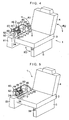
- Fig. 4 is a perspective view of an automobile seat mechanism using the embodiment shown in Fig. 1;
- Fig. 5 is a partly cutaway perspective view of the embodiment shown in Fig. 4;
- Fig. 6 is a diagram explaining the operation of the embodiment shown in Fig. 4;
- Fig. 7 is an explanatory cross-sectional view of another preferred embodiment of the invention;
- Fig. 8 is an explanatory cross-sectional view of still another preferred embodiment of the invention;
- Fig. 9 is a diagram explaining the operation of the embodiment shown in Fig. 8;
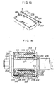
- Fig. 10 is an explanatory diagram of a further preferred embodiment of the invention;
- Fig. 11 is an explanatory partly enlarged cross-sectional view of the embodiment shown in Fig. 10;
- Fig. 12 is an explanatory partly enlarged cross-sectional view of the embodiment shown in Fig. 10;
- Fig. 13 is a diagram explaining the operation of the embodiment shown in Fig. 10;
- Fig. 14 is an explanatory diagram of a still further preferred embodiment of the invention;
- Fig. 15 is an explanatory diagram of a hollow cylinder used in the embodiment shown in Fig. 14;
- Fig. 16 is an explanatory diagram of a further preferred embodiment of the invention; and
- Fig. 17 is an explanatory diagram of a coil spring used in the embodiment shown in Fig. 14.
- In Figs. 1 to 5, an
automobile seat mechanism 1 in accordance with this embodiment is comprised of adamper 2 for an automobile seat; a seat, i.e., arear seat 3 in this embodiment, which is provided rotatably about an axis X with respect to an automobile chassis in lateral directions in raising and lowering directions, i.e., in directions of lateral rotation R1; abackrest 4 provided rotatably in a backward direction R2 with respect to therear seat 3; and aleg 5 provided rotatably in a lateral direction R3 with respect to therear seat 3. - The
damper 2 includes a fixingmember 12 adapted to be fixed to the chassis on which therear seat 3 of the automobile is installed rotatably in the directions of the lateral rotation R1; arotator 11 which is supported by the fixingmember 12 rotatably in the directions of the lateral rotation R1 and forms agap 13 with the fixingmember 12, and to which the lateral rotation R1 of the automobilerear seat 3 is adapted to be transmitted through a one-way clutch means 16; a silicone-basedunvulcanized rubber 15 disposed in thegap 13; and the one-way clutch means 16 which, in the lateral rotation R1 (the lowering rotation for returning therear seat 3 to its original position shown in Figs. 4 and 5) in the lowering direction of the automobilerear seat 3, is adapted to transmit the lateral rotation R1 in the lowering direction to therotator 11 so as to cause therotator 11 to undergo rotation about the axis X, and which, in the lateral rotation R1 (the springing-up rotation for bringing therear seat 3 to the position shown in Fig. 6) in the raising direction of the automobilerear seat 3, is adapted to inhibit the transmission of the lateral rotation R1 in the raising direction to therotator 11. - The
rotator 11 includes a cylindricalcentral shaft portion 21; a plurality of hollowcylindrical portions central shaft portion 21; a disk-shapedclosure portion 25 formed integrally with respective one axial end portions of the plurality of hollowcylindrical portions central shaft portion 21; acircular recess 26 provided in an axial end face of theclosure portion 25; and anannular detent member 27 fitted to the other axial end of thecentral shaft portion 21. - The fixing
member 12 has a plurality of hollowcylindrical portions central shaft portion 21; aclosure portion 43 formed integrally with one axial end portions of the hollowcylindrical portions portion 46 which is formed integrally with theclosure portion 43 and having throughholes 45 for insertion of fixingbolts 44; and arecess 47 which is formed in theclosure portion 43 and in which thedetent member 27 is disposed. The fixingmember 12 at the hollowcylindrical portion 41 on the innermost peripheral side between the plurality of hollowcylindrical portions central shaft portion 21, and rotatably supports therotator 11 to allow therotator 11 to be rotatable about the axis X. - The plurality of hollow
cylindrical portions rotator 11 and the plurality of hollowcylindrical portions member 12 are overlappingly fitted to each other in the radial direction with thegap 13 in which the silicone-basedunvulcanized rubber 15 is densely disposed. - The silicone-based
unvulcanized rubber 15, which has a Mooney viscosity of 10 to 150ML 1 + 4 (100°C), preferably a Mooney viscosity of 36 to 72ML 1 + 4 (100°C), more preferably a Mooney viscosity of 66 to 72ML 1 + 4 (100°C), still more preferably a Mooney viscosity of substantially 70ML 1 + 4 (100°C) and is constituted by a silicone-modified ethylene propylene rubber, is filled in thegap 13 in close contact with therotator 11 and the fixingmember 12. - The one-way clutch means 16 in accordance with this embodiment, which, in the lateral rotation R1 in the lowering direction of the automobile
rear seat 3, transmits the lateral rotation R1 in the lowering direction of therear seat 3 to therotator 11 so as to cause therotator 11 to rotate in the same direction, and which, in the lateral rotation R1 in the raising direction of the automobilerear seat 3, inhibits the transmission of the lateral rotation R1 in the lowering direction of therear seat 3 to therotator 11, has acoil spring 74 whose oneend portion 72 is formed as a free end is wound around a cylindrical outerperipheral surface 73 of therotator 11, specifically, the outerperipheral surface 73 of the hollowcylindrical potion 23, and whoseother end portion 71 curved in loop form is adapted to be attached to the automobilerear seat 3 through ahinge mechanism 82. - The
coil spring 74 is wound with such a winding direction that if thecoil spring 74 tends to be rotated in the same direction through thehinge mechanism 82 in the lateral rotation R1 in the raising direction of the automobilerear seat 3, its diameter is enlarged at the portion where thecoil spring 74 is in contact with and wound around the outerperipheral surface 73. As a result, thecoil spring 74 inhibits the transmission of such a lateral rotation R1 in the raising direction of therear seat 3 to therotator 11, so that relative rotation in the direction of the lateral rotation R1 about the axis X will not occur between therotator 11 and the fixingmember 12. Thus, thecoil spring 74 ensures that resistance against the lateral rotation R1 in the raising direction of the automobilerear seat 3 due to the shear deformation of the silicone-basedunvulcanized rubber 15 will not be produced. On the other hand, thecoil spring 74 is wound with such a winding direction that if thecoil spring 74 tends to be rotated in the same direction through thehinge mechanism 82 in the lateral rotation R1 in the lowering direction of the automobilerear seat 3, its diameter is reduced at the portion where thecoil spring 74 is in contact with and wound around the outerperipheral surface 73. As a result, thecoil spring 74 transmits the lateral rotation R1 in the lowering direction of therear seat 3 to therotator 11, thereby producing relative rotation in the direction of the lateral rotation R1 about the axis X between therotator 11 and the fixingmember 12. Thus, thecoil spring 74 is arranged to produce the resistance against the lateral rotation R1 in the lowering direction of the automobilerear seat 3 due to the shear deformation of the silicone-basedunvulcanized rubber 15, thereby allowing the energy of the lateral rotation R1 in the lowering direction of therear seat 3 to be partially absorbed by the silicone-basedunvulcanized rubber 15. - The
rear seat 3 is installed on a base 81 secured to the automobile chassis rotatably in the lateral rotation R1 through thedamper 2 and thehinge mechanism 82. Thus, therear seat 3 is provided on the automobile chassis rotatably in the direction of the lateral rotation R1 through thebase 81. - The
hinge mechanism 82 has abracket 83 secured to thebase 81; one arm member 88 which is connected at oneend portion 84 thereof to one bearingportion 85 of thebracket 83 rotatably in the direction of the lateral rotation R1 through ashaft member 86, and which is secured at theother end portion 87 thereof to therear seat 3; and anotherarm member 91 which at oneend portion 89 thereof supports ashaft member 24 inserted and secured in therecess 26 of therotator 11 of thedamper 2 rotatably in the directions of the lateral rotation R1, and which is secured at the other end portion 90 thereof to therear seat 3. - The mounting
portion 46 of the fixingmember 12 of thedamper 2 is secured by the fixingbolts 44 to a mountingportion 93 of thebracket 83 bridging the bearingportions - The
other end portion 71 of thecoil spring 74 curved in loop form is secured to the other end portion 90 of thearm member 91 through a mounting pin or the like. Thus, theother end portion 71 is attached to the automobilerear seat 3 through thehinge mechanism 82. Thecoil spring 74 is adapted to be rotated in the same direction when therear seat 3 is rotated in the directions of the lateral rotation R1. - The
backrest 4 is installed on therear seat 3 rotatably in the backward direction R2 relative to therear seat 3 through a known hinge mechanism 95 (see Fig. 6). Theleg 5 is also installed on therear seat 3 rotatably in the lateral direction R3 relative to therear seat 3 through a knownhinge mechanism 96. Since lock mechanisms and the like of thehinge mechanisms - According to the above-described
automobile seat mechanism 1 having thedamper 2, after thebackrest 4 is rotated in the backward direction R2, as shown in Fig. 6, if therear seat 3 is rotated in the raising direction in the lateral rotation R1, and theleg 5 is rotated in the lateral direction R3 relative to therear seat 3, it is possible to provide a large accommodating space inside the vehicle compartment. - Further, according to the automobile seat mechanism1, in the lateral rotation R1 in the raising direction of the
rear seat 3, thecoil spring 74 which is rotated in the same direction through thearm member 91 is adapted to undergo enlargement in diameter at the portion where it is in contact with and wound around the outerperipheral surface 73. As a result, thecoil spring 74 idles with respect to the outerperipheral surface 73, does not transmit the lateral rotation R1 in the raising direction of therear seat 3 to therotator 11, and does not allow the relative rotation in the direction of the lateral rotation R1 about the axis X to be produced between therotator 11 and the fixingmember 12. It is thereby ensured that the damping function based on the silicone-basedunvulcanized rubber 15 is not produced; therefore, it is possible to easily effect the springing up of therear seat 3 in the lateral direction. On the other hand, in the lateral rotation R1 in the lowering direction of therear seat 3, thecoil spring 74 which is rotated in the same direction through thearm member 91 is adapted to undergo shrinkage in diameter at the portion where it is in contact with and wound around the outerperipheral surface 73. As a result, thecoil spring 74 is tightly wound around the outerperipheral surface 73, transmits the lateral rotation R1 in the lowering direction of therear seat 3 to therotator 11, and allows the relative rotation in the direction of the lateral rotation R1 about the axis X to be produced between therotator 11 and the fixingmember 12. It is thereby ensured that the silicone-basedunvulcanized rubber 15 is made to undergo shear deformation, allowing the rotational energy of therear seat 3 to be absorbed by the shear deformation of the silicone-basedunvulcanized rubber 15. Therefore, it is possible to avoid sudden lateral rotation R1 in the returning and lowering direction of therear seat 3, eliminate the sudden returning of therear seat 3, and eliminate the generation of a large unpleasant noise due to a violent collision against the stopper or the like. - Further, according to the
damper 2, since the damping function is obtained by the shear deformation of the silicone-basedunvulcanized rubber 15, there is no possibility of wear, the seal for leakage prevention can be omitted, and it is possible to easily obtain a large damping force even with a lightweight and compact damper. Moreover, therotator 11 is supported at itsrecess 26 by thearm member 91 through theshaft member 24, while the fixingmember 12 is supported at its mountingportion 46 by the mountingportion 93, such that thedamper 2 is supported at its both ends. Therefore, thedamper 2 is firmly fixed to the chassis. - With the above-described
damper 2, the fixingmember 12 is formed by an integral member, but the fixingmember 12 may alternatively formed by twomembers damper 2 shown in Fig. 7, the onemember 151 of the fixingmember 12 includes acentral shaft portion 153; a plurality of hollowcylindrical portions axial end portion 154 side of thecentral shaft portion 153; aclosure portion 157 formed integrally with the oneaxial end portion 154 of thecentral shaft portion 153 and respective one axial end portions of the plurality of hollowcylindrical portions portion 46 formed integrally with theclosure portion 157 so as to be fixed to the chassis. Theother member 152 of the fixingmember 12 includes a plurality of hollowcylindrical portions axial end portion 160 side of thecentral shaft portion 153; theother closure portion 163 formed integrally with respective one axial end portions of the plurality of hollowcylindrical portions recess 26 provided in an axial end face of theclosure portion 163. The hollowcylindrical portion 161 on the innermost peripheral side between the plurality of hollowcylindrical portions axial end portion 160 of thecentral shaft portion 153 with serration (projection/recess) coupling. - In the
damper 2 shown in Fig. 7 and having such a fixingmember 12, therotator 11 constituted by an integral member includes two sets of pluralities of hollowcylindrical portions central shaft portion 153 and are arranged in the axial direction; and anannular closure portion 177 which is disposed between the two sets of pluralities of hollowcylindrical portions cylindrical portions rotator 11 is supported rotatably by thecentral shaft portion 153 between the twomembers member 12. Both pluralities of hollowcylindrical portions member 12 and the two sets of pluralities of hollowcylindrical portions gap 13 in which the silicone-basedunvulcanized rubber 15 is densely disposed. - In the
damper 2 shown in Fig. 7, thecoil spring 74 of the one-way clutch means 16 has oneend portion 72 formed as a free end and wound around a cylindrical outerperipheral surface 178 of therotator 11, specifically around the outerperipheral surface 178 of the hollowcylindrical portions closure portion 177, theother end portion 71 curved in loop form being adapted to be attached to the automobilerear seat 3 through thearm member 91 of thehinge mechanism 82. - In the same way as the
damper 2 shown in Fig. 1, thedamper 2 shown in Fig. 7 is secured at its mountingportion 46 to the mountingportion 93 of thebracket 83 by means of the fixingbolts 44, and is supported by thearm member 91 at therecess 26 via theshaft member 24 fitted in therecess 26. - Also in the
automobile seat mechanism 1 having thedamper 2 shown in Fig. 7, in the lateral rotation R1 in the raising direction of therear seat 3, thecoil spring 74 which is rotated in the same direction through thearm member 91 is adapted to undergo enlargement in diameter at the portion where it is in contact with and wound around the outerperipheral surface 178. As a result, thecoil spring 74 idles with respect to the outerperipheral surface 178, does not transmit the lateral rotation R1 in the raising direction of therear seat 3 to therotator 11, and does not allow the relative rotation in the direction of the lateral rotation R1 about the axis X to be produced between therotator 11 and the fixingmember 12. It is thereby ensured that the damping function based on the silicone-basedunvulcanized rubber 15 is not produced; therefore, it is possible to easily effect the springing up of therear seat 3 in the lateral direction. On the other hand, in the lateral rotation R1 in the lowering direction of therear seat 3, thecoil spring 74 which is rotated in the same direction through thearm member 91 is adapted to undergo shrinkage in diameter at the portion where it is in contact with and wound around the outerperipheral surface 178. As a result, thecoil spring 74 is tightly wound around the outerperipheral surface 178, transmits the lateral rotation R1 in the lowering direction of therear seat 3 to therotator 11, and allows the relative rotation in the direction of the lateral rotation R1 about the axis X to be produced between therotator 11 and the fixingmember 12. It is thereby ensured that the silicone-basedunvulcanized rubber 15 is made to undergo shear deformation, allowing the rotational energy of therear seat 3 to be absorbed by the shear deformation of the silicone-basedunvulcanized rubber 15. Therefore, it is possible to avoid sudden lateral rotation R1 in the returning and lowering direction of therear seat 3, eliminate the sudden returning of therear seat 3, and eliminate the generation of a large unpleasant noise due to a violent collision against the stopper or the like. Further, since the damping function can be obtained by the shear deformation of the silicone-basedunvulcanized rubber 15, there is no possibility of wear, the seal for leakage prevention can be omitted, and it is possible to easily obtain a large damping force even with a lightweight and compact damper. At the same time, therotator 11 is supported at itsrecess 26 by thearm member 91 through theshaft member 24, while the fixingmember 12 is supported at its mountingportion 46 by the mountingportion 93, such that thedamper 2 is supported at its both ends. Therefore, thedamper 2 is firmly fixed to the chassis. - Incidentally, although described above is the example of the
automobile seat mechanism 1 in which therear seat 3 is installed rotatably in the directions of the lateral rotation R1, thedamper 2 may alternatively be used in theautomobile seat mechanism 1 in which therear seat 3 is installed rotatably in back-and-forth directions R4, as shown in Fig. 8. - In the
automobile seat mechanism 1 shown in Fig. 8, thedamper 2 is accommodated in aside frame 101, and the fixingmember 12 of thedamper 2 has its mountingportion 46 secured to the automobile chassis by being secured to theside frame 101 or afloor plate 102 of the automobile. Theshaft member 24 disposed in therecess 26 and supported rotatably by theside frame 101 is inserted and secured in a hole of theother end 106 of aseat bracket 105 secured at oneend 104 thereof to therear seat 3, and rotatably supports theseat bracket 105. Theother end portion 71 of thecoil spring 74 curved in loop form is attached to a pin (not shown) which is embedded in theother end 106 of theseat bracket 105, is passed through a circular arc-shaped elongated hole of theside frame 101, and extends into theside frame 101. The rotation in back-and-forth direction R4 of therear seat 3 is adapted to be transmitted to theother end portion 71 of thecoil spring 74 through theseat bracket 105, so that thebackrest 4 is provided rotatably in a forward direction R5 relative to therear seat 3. Theother seat bracket 116 secured at oneend 115 thereof to therear seat 3 is supported at theother end 117 thereof to the other side frame (not shown) of the automobile through a shaft and the like so as to be rotatable in the back-and-forth directions R4. - Further, with the
automobile seat mechanism 1 shown in Fig. 8, after thebackrest 4 is rotated in the forward direction R5 and is superposed on the rear seat 3 (after being folded), therear seat 3 is rotated in the backward direction in the back-and-forth directions R4 and is then further rotated in the lowering direction, so as to be accommodated in arecess 121 formed in thefloor plate 102 of the automobile. Hence, it is possible to provide a large accommodating space inside the vehicle compartment, as shown in Fig. 9. In addition, in the state shown in Fig. 9, after therear seat 3 is rotated in the raising direction so as to be brought out from therecess 121, therear seat 3 is rotated in the forward direction in the back-and-forth directions R4, and is abutted against astopper 122 attached to theside frame 101. Subsequently, if thebackrest 4 is rotated, therear seat 3 can be returned to its original state. - With the
automobile seat mechanism 1 shown in Fig. 8, thecoil spring 74 is adapted to undergo shrinkage in diameter in the backward rotation of therear seat 3 including the lowering direction in the back-and-forth directions R4, and is adapted to undergo enlargement in diameter in the forward rotation of therear seat 3 including the raising direction in the back-and-forth directions R4. Thus, in this embodiment, in the backward rotation of therear seat 3 in the back-and-forth directions R4, the one-way clutch means 16 is adapted to transmit that backward rotation to therotator 11 and causes rotation in therotator 11, thereby allowing the relative rotation to be produced between therotator 11 and the fixingmember 12 on the basis of the backward rotation including the lowering direction in the back-and-forth directions R4. On the other hand, in the forward rotation of therear seat 3 including the raising direction in the back-and-forth directions R4, the one-way clutch means 16 is adapted to inhibit the transmission of that forward rotation to therotator 11 so as not to cause relative rotation between therotator 11 and the fixingmember 12 on the basis of the forward rotation including the raising direction in the back-and-forth directions R4. In other words, the silicone-basedunvulcanized rubber 15 is adapted to undergo shear deformation in the backward rotation of therear seat 3 including the lowering direction in the back-and-forth directions R4, whereas the silicone-basedunvulcanized rubber 15 is adapted not to undergo shear deformation in the forward rotation of therear seat 3 including the raising direction in the back-and-forth directions R4. - Although in the
automobile seat mechanism 1 shown in Fig. 8, thedamper 2 is accommodated in theside frame 101, thedamper 2 may alternatively be installed outside theside frame 101, or thedamper 2 may be installed also on theother seat bracket 116 side. - In addition, although in each of the above-described
dampers 2, therecess 26 is provided in theclosure portions shaft member 24 is fitted in therecess 26, instead of such a recess 26 a projection may be provided on each of theclosure portions shaft member 24. - Further, the
automobile seat mechanism 1 and thedamper 2 may be constructed, as shown in Figs. 10 to 12. Thedamper 2 shown in Figs. 10 to 12 includes a fixingmember 212; arotator 211 which is rotatable in the back-and-forth directions R4 relative to the fixingmember 212 and forms agap 213 with the fixingmember 212; a silicone-basedunvulcanized rubber 215 disposed in thegap 213; and a one-way clutch means 216 which, in the backward rotation of therear seat 3 in the back-and-forth directions R4, is adapted to transmit that backward rotation to therotator 211 to cause rotation in therotator 211, and which, in the forward rotation of therear seat 3 in the back-and-forth directions R4, is adapted to inhibit the transmission of that forward rotation to therotator 211. - The fixing
member 212, which is adapted to be fixed to the chassis on which therear seat 3 is installed rotatably in the back-and-forth directions R4, includes ahousing member 221, as well as anannular cover member 223 which is threadedly secured or fittingly secured, i.e., threadedly secured through a threadedportion 222 in this embodiment, to thehousing member 221. Thehousing member 221 includes an outer hollowcylindrical portion 224; an inner hollowcylindrical portion 225 disposed concentrically with the outer hollowcylindrical portion 224 on the inner side of the outer hollowcylindrical portion 224; and an annular plate-shapedclosure portion 226 which is formed integrally on the outer hollowcylindrical portion 224 and the inner hollowcylindrical portion 225 so as to close one axial end portions of the outer hollowcylindrical portion 224 and the inner hollowcylindrical portion 225. Thecover member 223 is threadedly secured to an inner peripheral surface of the other end portion in the direction of the axis X of the outer hollowcylindrical portion 224 through the threadedportion 222. Therotator 211 includes an outer peripheral hollowcylindrical portion 227 disposed concentrically with the outer hollowcylindrical portion 224 on the inner side of the outer hollowcylindrical portion 224 and on the outer side of the inner hollowcylindrical portion 225; an inner peripheral hollowcylindrical portion 228 connected to the outer peripheral hollowcylindrical portion 227 and disposed concentrically with the outer peripheral hollowcylindrical portion 227 on the inner side of the inner hollowcylindrical portion 225; and an intermediate hollowcylindrical portion 229 disposed concentrically with the outer peripheral hollowcylindrical portion 227 and disposed intermediate between the outer peripheral hollowcylindrical portion 227 and the inner peripheral hollowcylindrical portion 228 and on the inner side of the inner hollowcylindrical portion 225. The outer hollowcylindrical portion 224, the inner hollowcylindrical portion 225, and the outer peripheral hollowcylindrical portion 227 are overlappingly fitted to each other in the radial direction with thegap 213 in which the silicone-basedunvulcanized rubber 215 is disposed. The intermediate hollowcylindrical portion 229 and the inner hollowcylindrical portion 225 are overlappingly fitted to each other in the radial direction. It should be noted that such an intermediate hollowcylindrical portion 229 and the inner hollowcylindrical portion 225 may be overlappingly fitted to each other in the radial direction with a gap in which the silicone-basedunvulcanized rubber 215 is disposed. - The one-way clutch means 216 includes a collared hollow
cylindrical body 231 juxtaposed to the inner peripheral hollowcylindrical portion 228 in the direction of the axis X, as well as acoil spring 235 having oneend portion 232 formed as a free end and wound around respective hollow cylindrical outerperipheral surfaces cylindrical portion 228 and the hollowcylindrical body 231. The hollowcylindrical body 231 has on its inner peripheral surface a pair offlat surfaces 238 which oppose each other, so as to engage flat surfaces (two side portions) 237 formed on oneend portion 251 of ashaft member 236 which is inserted into its interior and to be rotated together with theshaft member 236. - The
coil spring 235 has an inside diameter of such a measure as to tighten the outerperipheral surface 234 of the hollowcylindrical body 231, and itsother end portion 241 is also formed as a free end in this embodiment. Alternatively, thecoil spring 235 may be secured and connected to the hollowcylindrical body 231 at theother end portion 241. - The fixing
member 212 is secured at its outer hollowcylindrical portion 224 to abase portion 246 of a mountingmember 245 by means of bolts, welding, or the like. The mountingmember 245 has, in addition to thebase portion 246, a pair ofshaft supporting portions 247 formed integrally with thebase portion 246. The mountingmember 245 is secured to the automobile chassis through bolts or the like inserted in bolt holes 248. The fixingmember 212 is adapted to be fixed through such a mountingmember 245 to the chassis on which therear seat 3 is rotatably installed. - The
shaft member 236 at its oneend portion 251 having theflat surfaces 237 is passed through thedamper 2 and the pair ofshaft supporting portions 247, and is supported by the pair ofshaft supporting portions 247 through collaredbushes nut 255 is secured to the oneend portion 251 through awasher 254 so that the oneend portion 251 does not come off thedamper 2 and theshaft supporting portion 247. In the same way as the oneend portion 251, theother end portion 256 of theshaft member 236 is also supported through another mountingmember 257 rotatably in the back-and-forth directions R4. The mountingmember 257 is secured to the automobile chassis through bolts or the like in the same way as the mountingmember 245. - The
shaft member 236 on its oneend portion 251 side is passed through a hole in the other end of aseat bracket 261 having one end secured to therear seat 3, and is secured to the other end of theseat bracket 261 by welding or the like. Meanwhile, theshaft member 236 on itsother end portion 256 side is passed through a hole in the other end of anotherseat bracket 262 having one end secured to therear seat 3, and is secured to the other end of theseat bracket 262 by welding or the like. Thus, therear seat 3 is rotatably installed on the automobile chassis through theshaft member 236 disposed by being passed through thedamper 2 as well as theseat brackets 261 and 267, and theshaft member 236 is adapted to be rotated in the same direction in conjunction with the rotation of therear seat 3 in the back-and-forth direction R4. - A
coil spring 265 having one end secured to theseat bracket 261 and the other end secured to theshaft member 236 and acoil spring 266 having one end secured to theseat bracket 262 and the other end secured to theshaft member 236 are disposed over theshaft member 236 concentrically therewith in such a manner as to surround theshaft member 236. Thecoil spring 265 is adapted to assist by its resiliency the backward rotation of therear seat 3 in the back-and-forth directions R4, while thecoil spring 266 is adapted to assist by its resiliency the forward rotation of therear seat 3 in the back-and-forth directions R4. - In the
automobile seat mechanism 1 shown in Figs. 10 to 12, if the backward rotation of therear seat 3 in the back-and-forth directions R4 is effected together with the assistance by the resiliency of thecoil spring 265 so as to accommodate therear seat 3 and thebackrest 4 in therecess 121, as shown in Fig. 13, the hollowcylindrical body 231 is also rotated in the same direction together with the rotation in the same direction of theshaft member 236. Thecoil spring 235 disposed to tighten the outerperipheral surface 234 of the hollowcylindrical body 231 undergoes shrinkage in diameter by the rotation of the hollowcylindrical body 231. Consequently, the outerperipheral surface 233 of the inner peripheral hollowcylindrical portion 228 is also tightened by thecoil spring 235, which causes the inner peripheral hollowcylindrical portion 228 to rotate together with the backward rotation of theshaft member 236 in the back-and-forth directions R4. As a result, relative rotation occurs between therotator 211 and the fixingmember 212 on the basis of the rotation in the back-and-forth directions R4, so that shear deformation occurs in the silicone-basedunvulcanized rubber 215, thereby absorbing the rotational energy of therear seat 3 by the shear deformation of the silicone-basedunvulcanized rubber 215. On the other hand, if the forward rotation of therear seat 3 in the back-and-forth directions R4 is effected, the hollowcylindrical body 231 is also rotated in the same direction together with the rotation in the same direction of theshaft member 236. Thecoil spring 235 disposed to tighten the outerperipheral surface 234 of the hollowcylindrical body 231 undergoes shrinkage in diameter by the rotation of the hollowcylindrical body 231. Consequently, thecoil spring 235 on the outerperipheral surface 233 of the inner peripheral hollowcylindrical portion 228 also undergoes enlargement in diameter, which causes the hollowcylindrical body 231 to idle with respect to thecoil spring 235 and the inner peripheral hollowcylindrical portion 228, so that relative rotation does not occur between therotator 211 and the fixingmember 212. Thus, the damping function based on the silicone-basedunvulcanized rubber 15 is not produced, and the forward rotation of therear seat 3 in the back-and-forth directions R4 is smoothly effected by the assistance based on the resiliency of thecoil spring 266. - Thus, with the one-way clutch means 216 as well, in the backward rotation of the
rear seat 3 in the back-and-forth directions R4, this backward rotation is transmitted to therotator 211 to cause rotation in therotator 211, thereby allowing relative rotation to occur between therotator 211 and the fixingmember 212 on the basis of the backward rotation in the back-and-forth directions R4. On the other hand, in the forward rotation of therear seat 3 in the back-and-forth directions R4, the transmission of this forward rotation to therotator 211 is inhibited, to ensure that relative rotation does not occur between therotator 211 and the fixingmember 212 on the basis of the forward rotation in the back-and-forth directions R4. In other words, in the backward rotation of therear seat 3 in the back-and-forth directions R4, the silicone-basedunvulcanized rubber 215 is made to undergo shear deformation, whereas in the forward rotation of therear seat 3 in the back-and-forth directions R4, the silicone-basedunvulcanized rubber 215 is made not to undergo shear deformation. - Further, according to the
automobile seat mechanism 1 shown in Figs. 10 to 12, since therear seat 3 is rotatably installed on the automobile chassis through theshaft member 236 which is disposed by being passed through thedamper 2 and is adapted to be rotated together with the rotation of therear seat 3, thedamper 2 can be disposed compactly around theshaft member 236. - In the
automobile seat mechanism 1 shown in Figs. 10 to 12, instead of providing thedamper 2 on only the oneend portion 251 side of theshaft member 236, thedamper 2 may be similarly provided also on theother end portion 256 side of theshaft member 236. - Incidentally, in the
automobile seat mechanism 1 shown in Figs. 10 to 12, theflat surfaces 237 and theflat surfaces 238 which engage each other are respectively provided on theshaft member 236 and the hollowcylindrical body 231 so as to rotate the hollowcylindrical body 231 together with the rotation of theshaft member 236. Alternatively, it is possible to provide a hollowcylindrical body 274 which has aslit 273 extending from oneannular end face 271 to the otherannular end face 272 in the direction of the axis X and which is capable of undergoing a reduction in diameter, so that the hollowcylindrical body 274 can be rotated in the back-and-forth directions R4 together with theshaft member 236 by tightening the oneend portion 251 of theshaft member 236 inserted in its interior, as shown in Figs. 14 and 15. Instead of the collared hollowcylindrical body 231, the hollowcylindrical body 274 is juxtaposed to the inner peripheral hollowcylindrical portion 228 in the direction of the axis X. In theautomobile seat mechanism 1 shown in Figs. 10 to 12, as theshaft member 236 rotates, the hollowcylindrical body 274 which tightened theshaft member 236 is also adapted to rotate, and thecoil spring 235 wound around the hollowcylindrical body 274 in such a manner as to tighten the hollowcylindrical body 274 is adapted to undergo shrinkage or enlargement in diameter by the rotation of the hollowcylindrical body 274, so as to effect the operation similar to the one described above. It should be noted that in thedamper 2 shown in Fig. 14, thecover member 223 is disposed on thenut 255 side, and is fitted to the oneend portion 251 of theshaft member 236. - In addition, as shown in the
automobile seat mechanism 1 shown in Figs. 16 and 17, the hollowcylindrical body 274 may be omitted, and thecoil spring 235 may be directly brought into contact with the oneend portion 251 of theshaft member 236, while thecoil spring 235 may be connected at itsother end portion 241 to the inner peripheral hollowcylindrical portion 228 of therotator 211. In this case, thecoil spring 235 has such an inside diameter that thecoil spring 235 tightens the oneend portion 251 of theshaft member 236 inserted in its interior, and that the oneend portion 232 which is its free end is rotated together with theshaft member 236. Thehousing member 221 has, in addition to the outer hollowcylindrical portion 224 and the inner hollowcylindrical portion 225, a further hollow cylindrical portion 281 which is formed integrally with theclosure portion 226 on the inner peripheral side of the inner hollowcylindrical portion 225 and the intermediate hollowcylindrical portion 229 concentrically therewith and in such a manner as to surround thecoil spring 235. - With the one-way clutch means 216 having the
coil spring 235 shown in Figs. 16 and 17, in the rotation of theshaft member 236 in the same direction due to the backward rotation of therear seat 3 in the back-and-forth directions R4, thecoil spring 235 is made to undergo shrinkage in diameter, is tightly wound around the oneend portion 251 of theshaft member 236, and is rotated together with the rotation of theshaft member 236. As a result, therotator 211 is rotated in the same direction. On the other hand, in the rotation of theshaft member 236 in the same direction due to the forward rotation of therear seat 3 in the back-and-forth directions R4, thecoil spring 235 is made to undergo enlargement in diameter, and is loosely wound around the oneend portion 251 of theshaft member 236. As a result, theshaft member 236 is idled with respect to thecoil spring 235, thereby preventing the transmission of the forward rotation of therear seat 3 in the back-and-forth directions R4 to therotator 211. - As in the
damper 2 shown in Figs. 16 and 17, the intermediate hollowcylindrical portion 229 and the inner hollowcylindrical portion 225 may be overlappingly fitted to each other in the radial direction with thegap 213 in which the silicone-basedunvulcanized rubber 215 is disposed. - Also with the
damper 2 having the one-way clutch means 216 shown in Figs. 16 and 17 and theautomobile seat mechanism 1 having such adamper 2, it is possible to obtain advantages similar to those described above, and since the hollowcylindrical body
Claims (26)
- A damper for an automobile seat comprising: a fixing member adapted to be fixed to a chassis on which an automobile seat is rotatably installed; a rotator which is rotatable relative to said fixing member and forms a gap with said fixing member; a silicone-based unvulcanized rubber disposed in the gap; and a one-way clutch means which, in the rotation of the automobile seat in one direction, is adapted to transmit the rotation in the one direction to said rotator, and which, in the rotation of the automobile seat in another direction, is adapted to inhibit the transmission of the rotation in the other direction to said rotator.
- The damper for an automobile seat according to claim 1, wherein said fixing member is adapted to be fixed to the chassis on which the automobile seat is installed rotatably in raising and lowering directions, and wherein in the lateral rotation of the automobile seat in the lowering direction, said one-way clutch means is adapted to transmit the lateral rotation in the lowering direction to said rotator so as to cause said rotator to rotate, whereas in the lateral rotation of the automobile seat in the raising direction, said one-way clutch means is adapted to inhibit the transmission of the lateral rotation in the raising direction to said rotator.
- The damper for an automobile seat according to claim 1, wherein said fixing member is adapted to be fixed to the chassis on which the automobile seat is installed rotatably in back-and-forth directions, and wherein in the backward rotation of the automobile seat, said one-way clutch means is adapted to transmit the backward rotation to said rotator so as to cause said rotator to rotate, whereas in the forward rotation of the automobile seat, said one-way clutch means is adapted to inhibit the transmission of the forward rotation to said rotator.
- The damper for an automobile seat according to any one of claims 1 to 3, wherein said rotator has a central shaft portion and a plurality of hollow cylindrical portions disposed concentrically with the central shaft portion, and said fixing member has a plurality of hollow cylindrical portions disposed concentrically with the central shaft portion and, at the hollow cylindrical portion on an innermost peripheral side among the plurality of hollow cylindrical portions, is fitted slidably over the central shaft portion to rotatably support said rotator, and wherein the plurality of hollow cylindrical portions of said rotator and the plurality of hollow cylindrical portions of said fixing member are overlappingly fitted to each other in a radial direction with the gap in which said silicone-based unvulcanized rubber is disposed.
- The damper for an automobile seat according to claim 4, wherein said rotator has a closure portion formed integrally with respective one axial end portions of the plurality of hollow cylindrical portions and a recess or a projection provided in or on an axial end face of said closure portion, and said fixing member has a closure portion formed integrally with one axial end portions of the hollow cylindrical portions and a mounting portion formed integrally with said closure portion and adapted to be fixed to the chassis.
- The damper for an automobile seat according to any one of claims 1 to 3, wherein said fixing member is constituted by two members, one of said members having a central shaft portion and a plurality of hollow cylindrical portions disposed concentrically on the one axial end portion side of the central shaft portion, another one of said members having a plurality of other hollow cylindrical portions disposed concentrically on another axial end portion side of the central shaft portion, wherein the hollow cylindrical portion on an innermost peripheral side among said plurality of other hollow cylindrical portions is fittingly secured in the other axial end portion of the central shaft portion, wherein said rotator includes two sets of pluralities of hollow cylindrical portions disposed concentrically with the central shaft portion and arranged in an axial direction and a closure portion disposed between said two sets of pluralities of hollow cylindrical portions and formed integrally with respective ones of said two sets of pluralities of hollow cylindrical portions, said rotator being supported rotatably by the central shaft portion between said two members of said fixing member, and wherein both pluralities of hollow cylindrical portions of said fixing member and said two sets of pluralities of hollow cylindrical portions are overlappingly fitted to each other in the radial direction with the gap in which said silicone-based unvulcanized rubber is disposed.
- The damper for an automobile seat according to claim 6, wherein said one member of said fixing member has a closure portion formed integrally with the one axial end portion of the central shaft portion and respective one axial end portions of the plurality of hollow cylindrical portions, as well as a mounting portion formed integrally with said closure portion so as to be fixed to the chassis, and said other member of said fixing member has another closure portion formed integrally with the respective one axial end portions of the plurality of other hollow cylindrical portions, as well as a recess or a projection provided in or on an axial end face of said closure portion.
- The damper for an automobile seat according to claim any one of claims 1 to 7, wherein said one-way clutch means has a coil spring whose one end portion is formed as a free end and wound around a cylindrical outer peripheral surface of said rotator and whose other end portion is adapted to be attached to an automobile rear seat.
- The damper for an automobile seat according to any one of claims 1 to 3, wherein said fixing member includes a housing member and a cover member which is threadedly secured or fittingly secured to said housing member, wherein said housing member includes an outer hollow cylindrical portion, an inner hollow cylindrical portion disposed concentrically with the outer hollow cylindrical portion on an inner side of the outer hollow cylindrical portion, and a closure portion formed integrally on the outer hollow cylindrical portion and the inner hollow cylindrical portion so as to close one axial end portions of the outer hollow cylindrical portion and the inner hollow cylindrical portion, wherein said cover member is threadedly secured or fittingly secured to another axial end portion of the outer hollow cylindrical portion, wherein said rotator includes an outer peripheral hollow cylindrical portion disposed concentrically with the outer hollow cylindrical portion on an inner side of the outer hollow cylindrical portion and on an outer side of the inner hollow cylindrical portion, an inner peripheral hollow cylindrical portion connected to the outer peripheral hollow cylindrical portion and disposed concentrically with the outer peripheral hollow cylindrical portion on an inner side of the inner hollow cylindrical portion, and wherein the outer peripheral hollow cylindrical portion and at least one of the outer hollow cylindrical portion and the inner hollow cylindrical portion are overlappingly fitted to each other in the radial direction with the gap in which said silicone-based unvulcanized rubber is disposed.
- The damper for an automobile seat according to claim 9, wherein said rotator further includes an intermediate hollow cylindrical portion disposed intermediate between the outer peripheral hollow cylindrical portion and the inner peripheral hollow cylindrical portion on the inner side of the inner hollow cylindrical portion, and wherein the intermediate hollow cylindrical portion and the inner hollow cylindrical portion are overlappingly fitted to each other in the radial direction with a gap in which said silicone-based unvulcanized rubber is disposed.
- The damper for an automobile seat according to claim 9 or 10, wherein said one-way clutch means includes a hollow cylindrical body juxtaposed to the inner peripheral hollow cylindrical portion in the axial direction, as well as a coil spring having one end portion formed as a free end and wound around respective outer peripheral surfaces of the inner peripheral hollow cylindrical portion and the hollow cylindrical body.
- The damper for an automobile seat according to claim 11, wherein the hollow cylindrical body has on an inner peripheral surface thereof a pair of flat surfaces which oppose each other, so as to engage a shaft member which is inserted into an interior thereof and to be rotated together with the shaft member.
- The damper for an automobile seat according to claim 11, wherein the hollow cylindrical body has a slit extending from one annular end face thereof to another annular end face thereof in the axial direction and which is capable of undergoing a reduction in diameter, so that the hollow cylindrical body can be rotated together with the shaft member by tightening the shaft member inserted in the interior thereof.
- The damper for an automobile seat according to any one of claims 11 to 13, wherein said coil spring has an inside diameter of such a measure as to tighten the hollow cylindrical body, and the other end portion thereof is also formed as a free end.
- The damper for an automobile seat according to claim 11, wherein said coil spring is connected at the other end portion thereof to said rotator, and has such an inside diameter that said coil spring tightens said shaft member inserted in the interior thereof, and that the one end portion which is the free end thereof is rotated together with said shaft member.
- The damper for an automobile seat according to any one of claims 1 to 15, wherein said silicone-based unvulcanized rubber has a degree of plasticity of 30 to 420.
- The damper for an automobile seat according to any one of claims 1 to 15, wherein said silicone-based unvulcanized rubber has a degree of plasticity of 60 to 320.
- The damper for an automobile seat according to any one of claims 1 to 15, wherein said silicone-based unvulcanized rubber has a degree of plasticity of 160 to 320.
- The damper for an automobile seat according to any one of claims 1 to 15, wherein said silicone-based unvulcanized rubber has a Mooney viscosity of 10 to 150 ML1 + 4(100°C).
- The damper for an automobile seat according to any one of claims 1 to 15, wherein said silicone-based unvulcanized rubber has a Mooney viscosity of 36 to 72 ML 1 + 4 (100°C).
- The damper for an automobile seat according to any one of claims 1 to 15, wherein said silicone-based unvulcanized rubber has a Mooney viscosity of 66 to 72 ML1 + 4 (100°C).
- The damper for an automobile seat according to any one of claims 1 to 21, wherein said silicone-based unvulcanized rubber is constituted by a silicone-modified ethylene propylene rubber.
- An automobile seat mechanism comprising: said damper for an automobile seat according to any one of claims 1 to 22; a seat provided rotatably with respect to the automobile chassis; and a backrest provided rotatably with respect to said seat.
- The automobile seat mechanism according to claim 23, wherein said backrest is provided rotatably in a backward direction with respect to said seat.
- The automobile seat mechanism according to claim 23 or 24, wherein said backrest is provided rotatably in a forward direction with respect to said seat.
- The automobile seat mechanism according to any one of claims 23 to 25, wherein said seat is provided rotatably with respect to the automobile chassis through a shaft member disposed in such a manner as to be passed through said damper, and said shaft member is adapted to be rotated together with the rotation of said seat.
Applications Claiming Priority (2)
| Application Number | Priority Date | Filing Date | Title |
|---|---|---|---|
| JP2003133689A JP4352756B2 (en) | 2002-07-18 | 2003-05-12 | Damper for automobile seat and automobile seat mechanism equipped with this damper |
| PCT/JP2004/001149 WO2004098944A1 (en) | 2003-05-12 | 2004-02-04 | Damper for car seat and car seat mechanism having the damper |
Publications (3)
| Publication Number | Publication Date |
|---|---|
| EP1623869A1 true EP1623869A1 (en) | 2006-02-08 |
| EP1623869A4 EP1623869A4 (en) | 2007-05-23 |
| EP1623869B1 EP1623869B1 (en) | 2008-10-22 |
Family
ID=33432197
Family Applications (1)
| Application Number | Title | Priority Date | Filing Date |
|---|---|---|---|
| EP04708046A Expired - Lifetime EP1623869B1 (en) | 2003-05-12 | 2004-02-04 | Damper for car seat and car seat mechanism having the damper |
Country Status (6)
| Country | Link |
|---|---|
| US (1) | US7597389B2 (en) |
| EP (1) | EP1623869B1 (en) |
| KR (1) | KR101059966B1 (en) |
| CN (4) | CN1787930B (en) |
| DE (1) | DE602004017301D1 (en) |
| WO (1) | WO2004098944A1 (en) |
Cited By (1)
| Publication number | Priority date | Publication date | Assignee | Title |
|---|---|---|---|---|
| US8757719B2 (en) | 2011-08-11 | 2014-06-24 | Toyota Boshoku Kabushiki Kaisha | Vehicle seat |
Families Citing this family (6)
| Publication number | Priority date | Publication date | Assignee | Title |
|---|---|---|---|---|
| US8769770B2 (en) * | 2008-09-15 | 2014-07-08 | Sca Hygiene Products Ab | Hinge arrangement |
| DE102009060167B4 (en) | 2009-12-23 | 2022-10-13 | Sitech Sitztechnik Gmbh | Arrangement of a vehicle seat within a vehicle |
| JP6576378B2 (en) * | 2017-02-27 | 2019-09-18 | 日本発條株式会社 | Vehicle seat |
| US9844272B1 (en) * | 2017-04-25 | 2017-12-19 | Seachrome Corporation | Lift assist systems and methods for adjustable seats |
| WO2020002545A1 (en) * | 2018-06-27 | 2020-01-02 | Basf Polyurethanes Gmbh | Friction damper for damping a tilting movement between two components of a vehicle, particularly a seat part and a backrest in a vehicle, and seat and vehicle with same |
| US11148556B2 (en) * | 2019-08-09 | 2021-10-19 | Mahindra N.A. Tech Center | Vehicle seat hinge assembly |
Family Cites Families (13)
| Publication number | Priority date | Publication date | Assignee | Title |
|---|---|---|---|---|
| JPH0678703B2 (en) * | 1989-05-02 | 1994-10-05 | スガツネ工業株式会社 | Damper for flap door using viscous fluid |
| US5211269A (en) * | 1989-05-02 | 1993-05-18 | Sugatsune Industrial Co., Ltd. | Damper for a flapdoor using viscous fluid |
| KR100251977B1 (en) * | 1991-10-29 | 2000-04-15 | 구로이시 이쿠오 | Footwork parking brake for automobiles and one-way dampers used in it |
| JPH05229411A (en) * | 1991-10-29 | 1993-09-07 | Oiles Ind Co Ltd | Unidirectional damper and pedal type parking brake for automobile using the damper |
| DE69211336T2 (en) * | 1992-07-08 | 1997-02-06 | Sugatsune Kogyo | Damping device for a folding seat |
| JP3196000B2 (en) | 1994-11-22 | 2001-08-06 | ダイハツ工業株式会社 | Space up sheet with slide mechanism |
| JP2844531B2 (en) * | 1997-01-24 | 1999-01-06 | 光洋ファスナー株式会社 | Rotation control damper |
| DE29721962U1 (en) * | 1997-12-12 | 1998-02-05 | Utescheny-Endos GmbH, 75059 Zaisenhausen | Damping device for a component movable about an axis of rotation |
| US6405410B1 (en) * | 1999-06-17 | 2002-06-18 | Nishikawa Kasei Co., Ltd. | Retractable assist grip and mounting method thereof |
| JP4524771B2 (en) * | 2001-01-26 | 2010-08-18 | 株式会社ニフコ | Rotating damper and assist grip device |
| DE60227862D1 (en) * | 2001-02-14 | 2008-09-11 | Oiles Industry Co Ltd | Damper and motor vehicle seat with such a damper |
| JP4352629B2 (en) * | 2001-04-26 | 2009-10-28 | オイレス工業株式会社 | Damper for automobile seat and automobile seat equipped with this damper |
| US6843526B2 (en) * | 2002-03-26 | 2005-01-18 | Hiroyuki Honda | Removable jump seat for a vehicle |
-
2004
- 2004-02-04 CN CN200480012695XA patent/CN1787930B/en not_active Expired - Fee Related
- 2004-02-04 WO PCT/JP2004/001149 patent/WO2004098944A1/en not_active Ceased
- 2004-02-04 KR KR1020057021145A patent/KR101059966B1/en not_active Expired - Fee Related
- 2004-02-04 CN CN2009101281336A patent/CN101503067B/en not_active Expired - Fee Related
- 2004-02-04 CN CN2009101281340A patent/CN101503068B/en not_active Expired - Fee Related
- 2004-02-04 CN CN2009101281355A patent/CN101503069B/en not_active Expired - Fee Related
- 2004-02-04 US US10/556,138 patent/US7597389B2/en not_active Expired - Lifetime
- 2004-02-04 EP EP04708046A patent/EP1623869B1/en not_active Expired - Lifetime
- 2004-02-04 DE DE602004017301T patent/DE602004017301D1/en not_active Expired - Lifetime
Cited By (1)
| Publication number | Priority date | Publication date | Assignee | Title |
|---|---|---|---|---|
| US8757719B2 (en) | 2011-08-11 | 2014-06-24 | Toyota Boshoku Kabushiki Kaisha | Vehicle seat |
Also Published As
| Publication number | Publication date |
|---|---|
| US20070001357A1 (en) | 2007-01-04 |
| CN1787930A (en) | 2006-06-14 |
| EP1623869A4 (en) | 2007-05-23 |
| CN1787930B (en) | 2010-05-12 |
| CN101503069A (en) | 2009-08-12 |
| CN101503067B (en) | 2011-04-06 |
| US7597389B2 (en) | 2009-10-06 |
| KR20050120817A (en) | 2005-12-23 |
| EP1623869B1 (en) | 2008-10-22 |
| CN101503067A (en) | 2009-08-12 |
| WO2004098944A1 (en) | 2004-11-18 |
| DE602004017301D1 (en) | 2008-12-04 |
| CN101503069B (en) | 2011-04-06 |
| CN101503068B (en) | 2011-04-06 |
| CN101503068A (en) | 2009-08-12 |
| KR101059966B1 (en) | 2011-08-26 |
Similar Documents
| Publication | Publication Date | Title |
|---|---|---|
| US7866451B2 (en) | Damper and automobile seat having the damper | |
| JP4063863B1 (en) | Headrest | |
| US7597389B2 (en) | Damper for automobile seat and automobile seat mechanism having the damper | |
| JP3467568B2 (en) | Vehicle seat back frame | |
| JP4352756B2 (en) | Damper for automobile seat and automobile seat mechanism equipped with this damper | |
| US20080314188A1 (en) | Steering Column Arrangement For A Motor Vehicle | |
| JP3891584B2 (en) | Armrest device | |
| JP4196566B2 (en) | Damper for automobile seat and automobile seat mechanism equipped with this damper | |
| JP2005121141A (en) | Ball joint structure | |
| JP2006192132A5 (en) | ||
| JP4352629B2 (en) | Damper for automobile seat and automobile seat equipped with this damper | |
| JP4628616B2 (en) | Armrest | |
| CN214189586U (en) | Vibration isolators for retractors, retractors and vehicles | |
| JP3983010B2 (en) | Truck shock absorber | |
| CN216833560U (en) | Anti-theft lock for motor vehicle | |
| JP2001334944A (en) | Impact absorptive steering device | |
| JP3301205B2 (en) | Mounting structure of torsion bar spring | |
| KR100783774B1 (en) | Mounting shock absorbing structure of steering column | |
| JP2005329810A (en) | Assist grip | |
| JPS64387Y2 (en) | ||
| KR19980044181U (en) | Car cabin mounting with improved noise and abrasion resistance | |
| JPH04116236U (en) | Emergency locking device for vehicle seats | |
| WO1995002527A1 (en) | Steering lock | |
| JP2014070641A (en) | Rotary damper | |
| JPS6311166B2 (en) |
Legal Events
| Date | Code | Title | Description |
|---|---|---|---|
| PUAI | Public reference made under article 153(3) epc to a published international application that has entered the european phase |
Free format text: ORIGINAL CODE: 0009012 |
|
| 17P | Request for examination filed |
Effective date: 20051110 |
|
| AK | Designated contracting states |
Kind code of ref document: A1 Designated state(s): DE FR GB |
|
| DAX | Request for extension of the european patent (deleted) | ||
| RBV | Designated contracting states (corrected) |
Designated state(s): DE FR GB |
|
| A4 | Supplementary search report drawn up and despatched |
Effective date: 20070424 |
|
| 17Q | First examination report despatched |
Effective date: 20070706 |
|
| GRAP | Despatch of communication of intention to grant a patent |
Free format text: ORIGINAL CODE: EPIDOSNIGR1 |
|
| RIN1 | Information on inventor provided before grant (corrected) |
Inventor name: IGARASHI, YOSHITERU,C/O OILES CORP. FUJISAWA PLANT Inventor name: HARADA, YOSHIHIRO,C/O OILES CORPORATION FUJISAWA P Inventor name: KOJIMA, MASAMITSU,C/O OILES CORPORATION FUJISAWA P |
|
| GRAS | Grant fee paid |
Free format text: ORIGINAL CODE: EPIDOSNIGR3 |
|
| GRAA | (expected) grant |
Free format text: ORIGINAL CODE: 0009210 |
|
| AK | Designated contracting states |
Kind code of ref document: B1 Designated state(s): DE FR GB |
|
| REG | Reference to a national code |
Ref country code: GB Ref legal event code: FG4D |
|
| REF | Corresponds to: |
Ref document number: 602004017301 Country of ref document: DE Date of ref document: 20081204 Kind code of ref document: P |
|
| PLBE | No opposition filed within time limit |
Free format text: ORIGINAL CODE: 0009261 |
|
| STAA | Information on the status of an ep patent application or granted ep patent |
Free format text: STATUS: NO OPPOSITION FILED WITHIN TIME LIMIT |
|
| 26N | No opposition filed |
Effective date: 20090723 |
|
| PGFP | Annual fee paid to national office [announced via postgrant information from national office to epo] |
Ref country code: FR Payment date: 20111215 Year of fee payment: 9 |
|
| PGFP | Annual fee paid to national office [announced via postgrant information from national office to epo] |
Ref country code: GB Payment date: 20120201 Year of fee payment: 9 |
|
| PGFP | Annual fee paid to national office [announced via postgrant information from national office to epo] |
Ref country code: DE Payment date: 20120405 Year of fee payment: 9 |
|
| GBPC | Gb: european patent ceased through non-payment of renewal fee |
Effective date: 20130204 |
|
| REG | Reference to a national code |
Ref country code: FR Ref legal event code: ST Effective date: 20131031 |
|
| REG | Reference to a national code |
Ref country code: DE Ref legal event code: R119 Ref document number: 602004017301 Country of ref document: DE Effective date: 20130903 |
|
| PG25 | Lapsed in a contracting state [announced via postgrant information from national office to epo] |
Ref country code: FR Free format text: LAPSE BECAUSE OF NON-PAYMENT OF DUE FEES Effective date: 20130228 Ref country code: DE Free format text: LAPSE BECAUSE OF NON-PAYMENT OF DUE FEES Effective date: 20130903 Ref country code: GB Free format text: LAPSE BECAUSE OF NON-PAYMENT OF DUE FEES Effective date: 20130204 |