EP1623094B1 - Gesteuerte aufweitung eines gebirgsankers - Google Patents
Gesteuerte aufweitung eines gebirgsankers Download PDFInfo
- Publication number
- EP1623094B1 EP1623094B1 EP04732534A EP04732534A EP1623094B1 EP 1623094 B1 EP1623094 B1 EP 1623094B1 EP 04732534 A EP04732534 A EP 04732534A EP 04732534 A EP04732534 A EP 04732534A EP 1623094 B1 EP1623094 B1 EP 1623094B1
- Authority
- EP
- European Patent Office
- Prior art keywords
- pressure
- control system
- installation
- rock bolt
- sequence
- Prior art date
- Legal status (The legal status is an assumption and is not a legal conclusion. Google has not performed a legal analysis and makes no representation as to the accuracy of the status listed.)
- Expired - Lifetime
Links
Images
Classifications
-
- E—FIXED CONSTRUCTIONS
- E21—EARTH OR ROCK DRILLING; MINING
- E21D—SHAFTS; TUNNELS; GALLERIES; LARGE UNDERGROUND CHAMBERS
- E21D20/00—Setting anchoring-bolts
-
- E—FIXED CONSTRUCTIONS
- E21—EARTH OR ROCK DRILLING; MINING
- E21D—SHAFTS; TUNNELS; GALLERIES; LARGE UNDERGROUND CHAMBERS
- E21D21/00—Anchoring-bolts for roof, floor in galleries or longwall working, or shaft-lining protection
-
- E—FIXED CONSTRUCTIONS
- E21—EARTH OR ROCK DRILLING; MINING
- E21D—SHAFTS; TUNNELS; GALLERIES; LARGE UNDERGROUND CHAMBERS
- E21D21/00—Anchoring-bolts for roof, floor in galleries or longwall working, or shaft-lining protection
- E21D21/0026—Anchoring-bolts for roof, floor in galleries or longwall working, or shaft-lining protection characterised by constructional features of the bolts
- E21D21/0073—Anchoring-bolts having an inflatable sleeve, e.g. hollow sleeve expanded by a fluid
Definitions
- the present invention is related to an improved method and apparatus for manual installation of rock bolts expandable by means of pressure.
- the manual installation of rock bolts includes an operator manually connecting an installation apparatus to a rock bolt.
- the installation apparatus comprises an installation arm connected to a pump system by means of which pressurisation of the rock bolt take place.
- a pressure media for example water
- a pressure media for example water
- the pump system and more specifically a high-pressure pump whereby the rock bolt is made to expand.
- the expanding of the rock bolt requires a pressurisation up to a certain level, and that this pressure is maintained for a period of time that is enough for the rock bolt to be allowed to expand.
- the pump system used for pressurisation of rock bolts normally comprises a control system with a low intelligence, and which only strives to keep the pressure from the high-pressure pump constant at a prescribed installation level.
- the required pressure depends on type of rock bolt, but is often 240 or 300 bar.
- EP 0 272 233 A1 shows a rock stabilizer expandable by means of pressure media for insertion in a drilltide where the rock stabilizer comprises a boss with means for detachable interaction with a chuck for expansion of the rock stabilizer.
- a problem with the present manual installation of rock bolts is that the installation procedure is difficult to handle for an operator. Since the operator applies the pressure by pressing in or releasing, respectively, a handle in an installation apparatus, the pressure may sometimes cease and it is also difficult for the operator to decide during how long time a certain pressure has been maintained, and thereby for how long the expansion of the rock bolt has been proceeded. It has turned out that an operator often overestimates the elapsed time when manually installing rock bolts, and is thereby inclined to interrupt the installation process prematurely. In rock bolting it has thus turned out that some of the rock bolts are insufficiently expanded; giving quality problems and inadequate reliability of the supporting of rock.
- a method for manual installation by pressurisation of expandable rock bolts comprising manual connection of a pressure source to a rock bolt to be expanded, in which an operator starts a sequence, whereby the rock bolt is pressurized to a predetermined pressure. It is ensured that the predetermined pressure is kept under a predetermined period of time, during installation in progress. Thereby an operator is prevented from prematurely, by mistake, interrupt an installation of a rock bolt, and the quality of the rock support may be guaranteed. An operator may however interrupt an installation by deliberately pressing a reset button, for example if he discovers a leakage or the like.
- a signal is given when the installation sequence is successfully performed.
- a signal is given off, and preferably also an error message, when the installation sequence has not been successfully performed.
- the operator is made aware of the fact that an installation has failed and may remake the installation. A quality assured installation of rock bolts is thereby provided.
- a timer or some other means for time metering, is cleared if the predetermined pressure during the predetermined time period is below an indicated pressure level, and is further restarted when the indicated pressure level is again reached. Thereby it is ensured that the pressure required for expanding a rock bolt completely is really held during a prescribed period of time.
- a chuck or another means used for the installation, holds its grip on a rock bolt until the predetermined period of time has elapsed. Thereby a secure and reliable installation of rock bolts is provided.
- the starting of the installation requires an action by an operator during a certain period of time before the sequence is started. Thereby a certain amount of time is given the operator to see any possible faults in the system and during which time the operator may prevent the start of the sequence.
- the present invention also relates to a control system for manual installation of an expandable rock bolt, whereby advantages corresponding to the above described are achieved.
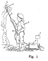
- An operator 1 has access to an installation apparatus for setting of rock bolts comprising an installation arm 2, with a handle 3 in one end and an installation chuck 4 in the other.
- the installation arm 2 is connected to a high-pressure pump 5, pumping out a pressure media, such as water, with a predetermined pressure into the rock bolt 6.
- a pressure media such as water
- the operator 1 starts an installation sequence, which he then may not interrupt other than by pressing a reset button, which is preferably placed on the high-pressure pump 5.
- the operator 1 only needs to start an installation sequence.
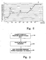
- phase marked 1 the rock bolt is filled with water (or other liquid), whereby the pressure need not be so high. Thereafter the pressure limit for permanent deformation is exceeded, marked by 2.
- phase 3 the pressure drops somewhat, and the indentation of the rock bolt unfolds and is pressed, in phase 4, to abutment to the rock.
- phase 4 elastic strain of the rock also occurs.
- the pressure reaches the prescribed limit. The pressure should be maintained at this level for a predetermined period of time, typically 6 seconds, in order to allow complete expansion of the rock bolt in the bore hole.
- Different bolts require different pressures, and even in rock bolts of the same kind the resistance may vary somewhat. A pressure slightly above 300 bars is however usually enough.
- the control system 7 in accordance with the present invention has as main function to ensure that the cycle, described in figure 2, cannot be interrupted manually by the operator 1.
- the operator 1 should thus not be able to interrupt the installation by lettibg go of the handle 3, and the installation sequence continues even if the operator 1 should release the handle 3.
- the control system 7 is shown in figure 1 only schematically as a separate unit connected to a high-pressure pump 5, but it is realised that it may constitute a part of the high-pressure pump 5, or for example form part elsewhere in the pump system.
- the control system 7 comprises means, for example a timer, that when a prescribed time has elapsed, makes a relay switch off the high-pressure pump 5.
- the rock bolt should be pressurised with a predetermined pressure during the period of time indicated in phase 5, say 6 seconds, and the chuck 4 does not loosen its grip of the rock bolt 6 before this time has elapsed. If the pressure during this phase should sink below the indicated pressure the timer is reset and restarted when the indicated pressure has again been reached.
- step 100 the operator manually connects a pressure source to a rock bolt to be expanded; in step 102 the operator starts a sequence whereby the rock bolt is pressurised to a predetermined pressure; and in step 104 the control system 7 ensures that the predetermined pressure is kept during a predetermined period of time, that cannot be affected by the operator.
- a sensor in the handle may give off a signal to the control system 7, whereby the installation sequence is started.
- the sensor is connected to a control system 7 controlling the high-pressure pump 5.
- the control system 7 then starts a time metering, for example by means of a timer, and controls that a set pressure is reached in the rock bolt during a certain, prescribed time (the time and the pressure corresponding to phase 5 in figure 2).
- a relay that receives a signal from the timer when the prescribed time has elapsed, may switch off the pressure source, for example the high-pressure pump 5.
- the time metering need not be governed by a mechanical unit, but may of course alternatively be accomplished by software.
- the three way valve described in the introduction may thus in the present invention be eliminated and be replaced with for example a sensor.
- rock bolt cannot be expanded, for example if there is no hole in the rock bolt. If that is the case, the pressure will reach the indicated value immediately and the sequence is interrupted after the predetermined period of time as usual. The rock bolt will then however not be expanded and there is no danger that a partly expanded rock bolt stays in the bore hole. Thereby the operator is aware of the fact that the rock bolt is defective and the quality of the rock support can thereby always be guaranteed.
- the control system 7 also handles the situation that come up when the prescribed pressure in the rock bolt cannot be reached, as is the case for example when a rock bolt is leaking.
- the operator may then stop the high-pressure pump by pressing the reset button on the handle of the installation arm or on the high-pressure pump itself, or the like.
- a function may be implemented where for example a timer controls that the sequence is performed within a prescribed maximum period of time, within which the prescribed pressure should have been reached and held during the prescribed time period.
- the timer is then set on a time period concerning the total installation time, and if this time period is exceeded the installation sequence is interrupted. It is important that the total installation time period set is not set to be too short, since the installation of the rock bolt then may be interrupted prematurely without the operator being aware of it.
- control system 7 comprises such a maximum installation time, after which the installation sequence is interrupted, a certain signal may be given off in order to alert the operator that the maximum time has been exceeded. Moreover, an error message may be presented to the operator, for example "Installation failed". The operator must then restart (reset) the system.
- the above function may be used when the pressure never reaches the prescribed and required level, but also if the pressure suddenly falls below this level before the required time has elapsed.
- the bolt is then not accurately installed, but has only expanded partly, and the control system 7 should then warn the operator.
- Partly expanded bolts may for example occur in case a rock bolt starts to leak, or if there arises a leakage in the pump system. Since the operator, in accordance with the present invention, may only interrupt an installation manually by pressing a reset button, and since he otherwise will be presented with an error message or a signal, he will thus always be aware of the case that a rock bolt has not been installed correctly.
- the control system 7 senses this, in an alternative embodiment.
- the control system 7 controls that the increase of pressure is normal, which is not the case for example if there is no rock bolt.
- the control system 7 then interrupts the sequence and an immediate restart of the same is possible.
- the starting of the installation requires action of the operator during a certain determined period of time, for example that the operator presses the handle during a certain period of time, say 2 seconds, before the sequence is started and is so to say locked and can no longer be interrupted by the operator.
- the operator has time to see for example if there is a leakage in the pump system, and may then prevent the start of the sequence.
- control system 7 may also include a counter registering the number of correctly installed bolts. This may for example be advantageous when it is critically important that a certain number of rock bolts have been installed or if statistics is desired.
- the expansion of a rock bolt cannot be interrupted prematurely by mistake, and thereby there is no risk for the anchorage of the rock bolt into the rock to be reduced and thereby to render the supporting of rock deficient.
- the control system 7 in accordance with the present invention ensures that the rock bolt 6 is-pressurised with a prescribed pressure and that the pressure is then held during a prescribed, required period of time. This provides a very reliable manual installation of rock bolts.
- the invention provides the possibility to store pressure and time for individual bolts for later quality follow-up.
Landscapes
- Engineering & Computer Science (AREA)
- Mining & Mineral Resources (AREA)
- Geology (AREA)
- Life Sciences & Earth Sciences (AREA)
- General Life Sciences & Earth Sciences (AREA)
- Geochemistry & Mineralogy (AREA)
- Structural Engineering (AREA)
- Earth Drilling (AREA)
- Dowels (AREA)
- Piles And Underground Anchors (AREA)
- Joining Of Building Structures In Genera (AREA)
- Drilling And Exploitation, And Mining Machines And Methods (AREA)
- Control Of Positive-Displacement Pumps (AREA)
- Pharmaceuticals Containing Other Organic And Inorganic Compounds (AREA)
- Control Of Electric Motors In General (AREA)
- Vehicle Body Suspensions (AREA)
- Transition And Organic Metals Composition Catalysts For Addition Polymerization (AREA)
- Hand Tools For Fitting Together And Separating, Or Other Hand Tools (AREA)
- Iron Core Of Rotating Electric Machines (AREA)
- Sowing (AREA)
Claims (16)
- Verfahren zur manuellen Installation von aufweitbaren Gesteinsankern durch Druckbeaufschlagung, mit einer manuellen Verbinden einer Druckquelle mit einem aufzuweitenden Gesteinsanker, dadurch gekennzeichnet, dass das Verfahren folgende Schritte umfasst:Starten einer Sequenz durch eine Bedienperson, wodurch der Gesteinsanker bis zu einem vorher festgelegten Druck mit Druck beaufschlagt wird, undSicherstellen, dass der vorher festgelegte Druck für eine vorher festgelegte Zeitdauer mittels der Sequenz und einer Vorrichtung gehalten wird, die ein Steuersystem aufweist, welches Mittel eines Steuersystems zur Gewährleistung aufweist, dass der Druck während einer vorher festgelegten Zeitdauer gehalten wird.
- Verfahren nach Anspruch 1, bei welchem ein Signal abgegeben wird, wenn die Sequenz erfolgreich ausgeführt worden ist.
- Verfahren nach Anspruch 1 oder 2, bei welchem ein Signal abgegeben wird, wenn die Sequenz nicht erfolgreich ausgeführt worden ist.
- Verfahren nach einem der Ansprüche 1 bis 3, bei welchem eine Fehlermitteilung abgegeben wird, wenn die Sequenz nicht erfolgreich ausgeführt worden ist.
- Verfahren nach einem der Ansprüche 1 bis 4, bei welchem eine Zeituhr gelöscht wird, wenn der vorher festgelegte Druck während der vorher festgelegten Zeitdauer unterhalb eines festgesetzten Druckwerts fällt, und wieder neu gestartet wird, wenn der festgesetzte Druckwert wieder erreicht wird.
- Verfahren nach einem der vorhergehenden Ansprüche, bei welchem ein für die Installation verwendetes Futter seinen Halt eines Gesteinsankers nicht freigibt, bevor die vorher festgelegte Zeitdauer vergangen ist.
- Verfahren nach einem der vorhergehenden Ansprüche, bei welchem das Starten der Installation über eine bestimmte festgelegte Zeitdauer ein Einwirken von einer Bedienperson erfordert, bevor die Sequenz gestartet wird.
- Steuersystem für die Verbindung mit einer Druckquelle zur manuellen Installation von aufweitbaren Gesteinsankern durch Druckbeaufschlagung, dadurch gekennzeichnet, dass das Steuersystem (7)Mittel zur Gewährleistung, dass der Gesteinsanker bis zu einem vorher festgelegten Druck mit Druck beaufschlagt wird, undMittel zur Gewährleistung, dass der Druck während einer vorher festgelegten Zeitdauer gehalten wird, aufweist.
- Steuersystem nach Anspruch 8, bei welchem die Mittel zur Gewährleistung eines Drucks eine Zeituhr aufweisen, mit der die Dauer des vorher festgelegten Drucks erfassbar ist.
- Steuersystem nach Anspruch 9, bei welchem die Zeituhr löschbar ist, wenn der gewünschte Druck während einer vorher festgelegten Zeitdauer unterhalb einen gegebenen Druckwert fällt, und die weiter neu startbar ist, wenn der gegebene Druckwert wieder erreicht ist.
- Steuersystem nach einem der Ansprüche 8 bis 10, bei weichem das Steuersystem (7) einen Rückstellknopf aufweist, um eine Unterbrechung der Installation zu ermöglichen.
- Steuersystem nach einem der Ansprüche 8 bis 11, bei welchem das Steuersystem (7) einen Zähler aufweist, der die Zahl der ordnungsgemäß installierten Gesteinsanker zählt.
- Steuersystem nach einem der Ansprüche 8 bis 12, bei welchem das Steuersystem (7) Mittel aufweist, mit denen ein Signal ausgebbar ist, wenn die Installation erfolgreich war.
- Steuersystem nach einem der Ansprüche 8 bis 13, bei welchem das Steuersystem (7) Mittel aufweist, mit denen ein Signal ausgebbar ist, wenn die Installation nicht erfolgreich verlaufen ist.
- Steuersystem nach einem der Ansprüche 8 bis 14, bei welchem eine Fehlermitteilung abgegeben wird, wenn die Sequenz nicht erfolgreich ausgeführt worden ist.
- Vorrichtung zum Installieren eines mittels Druckbeaufschlagung aufweitbaren Gesteinsankers, wobei die Vorrichtung eine Druckquelle und Mittel zum manuellen Koppeln an einen aufweitbaren Gesteinsanker umfasst, dadurch gekennzeichnet, dass die Vorrichtung ein Steuersystem (7) nach einem der Ansprüche 8 bis 15 aufweist.
Priority Applications (2)
| Application Number | Priority Date | Filing Date | Title |
|---|---|---|---|
| PL04732534T PL1623094T3 (pl) | 2003-05-12 | 2004-05-12 | Kontrolowane rozszerzanie żerdzi kotwowych |
| SI200430646T SI1623094T1 (sl) | 2003-05-12 | 2004-05-12 | Krmiljeno raztezanje sidrnega vijaka |
Applications Claiming Priority (2)
| Application Number | Priority Date | Filing Date | Title |
|---|---|---|---|
| SE0301377A SE525179C2 (sv) | 2003-05-12 | 2003-05-12 | Metod och reglersystem för genom trycksättning expanderbara bergbultar |
| PCT/SE2004/000733 WO2004099570A1 (en) | 2003-05-12 | 2004-05-12 | Controlled expansion of rock bolt |
Publications (2)
| Publication Number | Publication Date |
|---|---|
| EP1623094A1 EP1623094A1 (de) | 2006-02-08 |
| EP1623094B1 true EP1623094B1 (de) | 2008-01-09 |
Family
ID=20291275
Family Applications (1)
| Application Number | Title | Priority Date | Filing Date |
|---|---|---|---|
| EP04732534A Expired - Lifetime EP1623094B1 (de) | 2003-05-12 | 2004-05-12 | Gesteuerte aufweitung eines gebirgsankers |
Country Status (22)
| Country | Link |
|---|---|
| US (1) | US7320560B2 (de) |
| EP (1) | EP1623094B1 (de) |
| JP (1) | JP2006526093A (de) |
| KR (1) | KR20060012603A (de) |
| CN (1) | CN1791734B (de) |
| AT (1) | ATE383497T1 (de) |
| AU (1) | AU2004236623B2 (de) |
| BR (1) | BRPI0410167B1 (de) |
| CA (1) | CA2525458C (de) |
| DE (1) | DE602004011207T2 (de) |
| DK (1) | DK1623094T3 (de) |
| ES (1) | ES2297419T3 (de) |
| HR (1) | HRP20080031T3 (de) |
| IL (1) | IL171669A (de) |
| NO (1) | NO336673B1 (de) |
| PL (1) | PL1623094T3 (de) |
| PT (1) | PT1623094E (de) |
| RU (1) | RU2338067C2 (de) |
| SE (1) | SE525179C2 (de) |
| SI (1) | SI1623094T1 (de) |
| WO (1) | WO2004099570A1 (de) |
| ZA (1) | ZA200508477B (de) |
Families Citing this family (5)
| Publication number | Priority date | Publication date | Assignee | Title |
|---|---|---|---|---|
| SE528911C2 (sv) * | 2005-01-19 | 2007-03-13 | Atlas Copco Rock Drills Ab | Förfarande och system för övervakning och dokumentering av installation av bergförstärkningsbult |
| SE531009C2 (sv) * | 2005-05-03 | 2008-11-18 | Atlas Copco Rock Drills Ab | Anordning och förfarande för att installera en bergbult och en bergbultinstallationsrigg |
| KR101358946B1 (ko) * | 2012-12-05 | 2014-02-07 | 코오롱글로벌 주식회사 | 락볼트 체결용 장치 및 락볼트 체결용 장치의 구동방법 |
| CZ2016244A3 (cs) | 2016-04-28 | 2017-06-28 | Dsi Underground Ip Holdings Luxembourg Sarl | Rozpínatelný horninový svorník s indikátorem upnutí |
| KR101696374B1 (ko) | 2016-04-28 | 2017-01-13 | 주식회사 에이치아이씨 | 설치 상태의 점검이 가능한 팽창형 락볼트의 시공방법 |
Family Cites Families (13)
| Publication number | Priority date | Publication date | Assignee | Title |
|---|---|---|---|---|
| SE427764B (sv) * | 1979-03-09 | 1983-05-02 | Atlas Copco Ab | Bergbultningsforfarande jemte rorformig bergbult |
| NO159201C (no) * | 1980-09-08 | 1988-12-07 | Atlas Copco Ab | Fremgangsmaate ved bolting i fjell og kombinert ekspansjonsbolt og installasjonsanordning for samme. |
| US4954017A (en) * | 1980-11-10 | 1990-09-04 | The Curators Of The University Of Missouri | Expansion bolt and mine roof reinforcement |
| SE8106165L (sv) * | 1981-10-19 | 1983-04-20 | Atlas Copco Ab | Forfarande for bergbultning och bergbult |
| SE457894B (sv) * | 1985-06-17 | 1989-02-06 | Atlas Copco Ab | Saett att stabilisera berg |
| SE8605408D0 (sv) | 1986-12-16 | 1986-12-16 | Atlas Copco Ab | Method of stabilizing a rock structure and stabilizer therefor |
| SU1737130A1 (ru) * | 1990-06-21 | 1992-05-30 | Институт Горного Дела Ан Казсср | Анкер |
| CN1073501A (zh) * | 1991-12-19 | 1993-06-23 | 新汶矿务局 | 水力膨胀式锚杆防采煤面片帮冒顶 |
| RU2072048C1 (ru) * | 1992-12-29 | 1997-01-20 | Сергей Алексеевич Логашкин | Анкер |
| SE502795C2 (sv) * | 1994-06-02 | 1996-01-15 | Atlas Copco Rock Drills Ab | Rörformig bergbult med orienteringsmedel |
| SE9600640L (sv) * | 1996-02-21 | 1997-03-17 | Atlas Copco Rock Drills Ab | Skarvning av en rörformad bergbult |
| JPH10140998A (ja) * | 1996-11-13 | 1998-05-26 | Fujita Corp | 地山の安定化方法 |
| JP3630516B2 (ja) * | 1997-01-27 | 2005-03-16 | 日立建機株式会社 | 自動運転ショベル |
-
2003
- 2003-05-12 SE SE0301377A patent/SE525179C2/sv not_active IP Right Cessation
-
2004
- 2004-05-12 ZA ZA200508477A patent/ZA200508477B/en unknown
- 2004-05-12 KR KR1020057021527A patent/KR20060012603A/ko not_active Ceased
- 2004-05-12 ES ES04732534T patent/ES2297419T3/es not_active Expired - Lifetime
- 2004-05-12 AT AT04732534T patent/ATE383497T1/de active
- 2004-05-12 RU RU2005138521/03A patent/RU2338067C2/ru active
- 2004-05-12 BR BRPI0410167A patent/BRPI0410167B1/pt not_active IP Right Cessation
- 2004-05-12 PL PL04732534T patent/PL1623094T3/pl unknown
- 2004-05-12 DE DE602004011207T patent/DE602004011207T2/de not_active Expired - Lifetime
- 2004-05-12 CA CA2525458A patent/CA2525458C/en not_active Expired - Fee Related
- 2004-05-12 EP EP04732534A patent/EP1623094B1/de not_active Expired - Lifetime
- 2004-05-12 WO PCT/SE2004/000733 patent/WO2004099570A1/en not_active Ceased
- 2004-05-12 US US10/555,026 patent/US7320560B2/en not_active Expired - Lifetime
- 2004-05-12 SI SI200430646T patent/SI1623094T1/sl unknown
- 2004-05-12 JP JP2006508055A patent/JP2006526093A/ja active Pending
- 2004-05-12 DK DK04732534T patent/DK1623094T3/da active
- 2004-05-12 CN CN2004800128692A patent/CN1791734B/zh not_active Expired - Fee Related
- 2004-05-12 PT PT04732534T patent/PT1623094E/pt unknown
- 2004-05-12 AU AU2004236623A patent/AU2004236623B2/en not_active Ceased
- 2004-05-12 HR HR20080031T patent/HRP20080031T3/xx unknown
-
2005
- 2005-10-30 IL IL171669A patent/IL171669A/en not_active IP Right Cessation
- 2005-12-09 NO NO20055862A patent/NO336673B1/no not_active IP Right Cessation
Also Published As
| Publication number | Publication date |
|---|---|
| SI1623094T1 (sl) | 2008-06-30 |
| PT1623094E (pt) | 2008-01-29 |
| DE602004011207T2 (de) | 2008-12-24 |
| DE602004011207D1 (de) | 2008-02-21 |
| RU2338067C2 (ru) | 2008-11-10 |
| CA2525458C (en) | 2012-11-27 |
| WO2004099570A1 (en) | 2004-11-18 |
| CN1791734A (zh) | 2006-06-21 |
| CA2525458A1 (en) | 2004-11-18 |
| IL171669A (en) | 2010-02-17 |
| HRP20080031T3 (hr) | 2008-02-29 |
| ATE383497T1 (de) | 2008-01-15 |
| NO336673B1 (no) | 2015-10-19 |
| RU2005138521A (ru) | 2006-06-10 |
| WO2004099570A8 (en) | 2005-12-08 |
| EP1623094A1 (de) | 2006-02-08 |
| AU2004236623A1 (en) | 2004-11-18 |
| PL1623094T3 (pl) | 2008-05-30 |
| ZA200508477B (en) | 2007-05-30 |
| AU2004236623B2 (en) | 2008-12-18 |
| ES2297419T3 (es) | 2008-05-01 |
| KR20060012603A (ko) | 2006-02-08 |
| SE0301377D0 (sv) | 2003-05-12 |
| SE0301377L (sv) | 2004-11-13 |
| BRPI0410167A (pt) | 2006-05-16 |
| DK1623094T3 (da) | 2008-04-28 |
| JP2006526093A (ja) | 2006-11-16 |
| SE525179C2 (sv) | 2004-12-21 |
| NO20055862L (no) | 2006-02-03 |
| CN1791734B (zh) | 2012-10-10 |
| US7320560B2 (en) | 2008-01-22 |
| US20070036614A1 (en) | 2007-02-15 |
| BRPI0410167B1 (pt) | 2016-08-16 |
Similar Documents
| Publication | Publication Date | Title |
|---|---|---|
| CA2525458C (en) | Controlled expansion of rock bolt | |
| JPH07225686A (ja) | プログラムダウンロード方式 | |
| EP4308016B1 (de) | Automatische staubindevorrichtung mit patientenwarnmittel | |
| JPS6233155B2 (de) | ||
| JPH06136967A (ja) | 構造物の不同沈下修正装置 | |
| JP3056205B1 (ja) | 水系自動消火設備 | |
| JP2020085368A (ja) | ヒートポンプ式給湯機 | |
| KR101696374B1 (ko) | 설치 상태의 점검이 가능한 팽창형 락볼트의 시공방법 | |
| KR100411560B1 (ko) | 보일러의 실내온도 개별 조절 시스템의 통신불량검출방법 | |
| JP2001107875A (ja) | 給水装置 | |
| KR200416714Y1 (ko) | 접점압력계를 이용한 압력약탕기 압력자동 조절 장치 | |
| JP3261979B2 (ja) | 気泡浴槽のポンプ制御方法 | |
| JPH0370985B2 (de) | ||
| JP3205034B2 (ja) | 浴槽装置 | |
| JP2780839B2 (ja) | 温水暖房装置における循環水の初期注入方法 | |
| JP3570906B2 (ja) | 水中ポンプの制御装置 | |
| CN121539207A (zh) | 一种全通径漂浮下套管装置 | |
| JP2615537B2 (ja) | トルコンオイルチェンジャー | |
| JPH06149557A (ja) | ファームウェア自動リカバリ方式 | |
| JP2009187051A (ja) | 情報処理装置の製造方法および電源接続切断装置 | |
| JPH0882404A (ja) | ボイラ起動時における水位制御筒の詰まり検出方法 | |
| JPH05317449A (ja) | 消火設備の自動点検装置 | |
| JP2001221673A (ja) | 燃料タンクの液面監視システム | |
| JPH03132000A (ja) | 自動販売機の製氷装置 | |
| JPH0370984B2 (de) |
Legal Events
| Date | Code | Title | Description |
|---|---|---|---|
| PUAI | Public reference made under article 153(3) epc to a published international application that has entered the european phase |
Free format text: ORIGINAL CODE: 0009012 |
|
| 17P | Request for examination filed |
Effective date: 20051119 |
|
| AK | Designated contracting states |
Kind code of ref document: A1 Designated state(s): AT BE BG CH CY CZ DE DK EE ES FI FR GB GR HU IE IT LI LU MC NL PL PT RO SE SI SK TR |
|
| AX | Request for extension of the european patent |
Extension state: HR LV |
|
| RAX | Requested extension states of the european patent have changed |
Extension state: HR Payment date: 20051119 Extension state: LV Payment date: 20051119 |
|
| 17Q | First examination report despatched |
Effective date: 20061227 |
|
| RIN1 | Information on inventor provided before grant (corrected) |
Inventor name: PERSSON, TOMMY Inventor name: OERJAS, NICLAS Inventor name: KANFLOD, MORGAN Inventor name: SJOESTEDT, GOERAN Inventor name: TOIVONEN, TAPIO Inventor name: GUSTAVSSON, HANS Inventor name: OEBERG, FREDRIK |
|
| RIN1 | Information on inventor provided before grant (corrected) |
Inventor name: OERJAS, NICLAS Inventor name: PERSSON, TOMMY Inventor name: GUSTAVSSON, HANS Inventor name: SJOESTEDT, GOERAN Inventor name: TOIVONEN, TAPIO Inventor name: OEBERG, FREDRIK Inventor name: KANFLOD, MORGAN |
|
| GRAP | Despatch of communication of intention to grant a patent |
Free format text: ORIGINAL CODE: EPIDOSNIGR1 |
|
| GRAS | Grant fee paid |
Free format text: ORIGINAL CODE: EPIDOSNIGR3 |
|
| GRAA | (expected) grant |
Free format text: ORIGINAL CODE: 0009210 |
|
| AK | Designated contracting states |
Kind code of ref document: B1 Designated state(s): AT BE BG CH CY CZ DE DK EE ES FI FR GB GR HU IE IT LI LU MC NL PL PT RO SE SI SK TR |
|
| AX | Request for extension of the european patent |
Extension state: HR LV |
|
| REG | Reference to a national code |
Ref country code: GB Ref legal event code: FG4D |
|
| REG | Reference to a national code |
Ref country code: HR Ref legal event code: TUEP Ref document number: P20080031 Country of ref document: HR |
|
| REG | Reference to a national code |
Ref country code: PT Ref legal event code: SC4A Free format text: AVAILABILITY OF NATIONAL TRANSLATION Effective date: 20080116 |
|
| REG | Reference to a national code |
Ref country code: CH Ref legal event code: NV Representative=s name: BRAUNPAT BRAUN EDER AG Ref country code: CH Ref legal event code: EP |
|
| REG | Reference to a national code |
Ref country code: IE Ref legal event code: FG4D |
|
| REG | Reference to a national code |
Ref country code: RO Ref legal event code: EPE |
|
| REF | Corresponds to: |
Ref document number: 602004011207 Country of ref document: DE Date of ref document: 20080221 Kind code of ref document: P |
|
| REG | Reference to a national code |
Ref country code: HR Ref legal event code: T1PR Ref document number: P20080031 Country of ref document: HR |
|
| REG | Reference to a national code |
Ref country code: GR Ref legal event code: EP Ref document number: 20080400511 Country of ref document: GR |
|
| REG | Reference to a national code |
Ref country code: DK Ref legal event code: T3 |
|
| REG | Reference to a national code |
Ref country code: ES Ref legal event code: FG2A Ref document number: 2297419 Country of ref document: ES Kind code of ref document: T3 |
|
| REG | Reference to a national code |
Ref country code: PL Ref legal event code: T3 |
|
| PG25 | Lapsed in a contracting state [announced via postgrant information from national office to epo] |
Ref country code: SE Free format text: LAPSE BECAUSE OF FAILURE TO SUBMIT A TRANSLATION OF THE DESCRIPTION OR TO PAY THE FEE WITHIN THE PRESCRIBED TIME-LIMIT Effective date: 20080409 |
|
| PLBE | No opposition filed within time limit |
Free format text: ORIGINAL CODE: 0009261 |
|
| STAA | Information on the status of an ep patent application or granted ep patent |
Free format text: STATUS: NO OPPOSITION FILED WITHIN TIME LIMIT |
|
| REG | Reference to a national code |
Ref country code: EE Ref legal event code: HC1A Ref document number: E002032 Country of ref document: EE |
|
| 26N | No opposition filed |
Effective date: 20081010 |
|
| PG25 | Lapsed in a contracting state [announced via postgrant information from national office to epo] |
Ref country code: MC Free format text: LAPSE BECAUSE OF NON-PAYMENT OF DUE FEES Effective date: 20080531 |
|
| REG | Reference to a national code |
Ref country code: HU Ref legal event code: AG4A Ref document number: E005070 Country of ref document: HU |
|
| PG25 | Lapsed in a contracting state [announced via postgrant information from national office to epo] |
Ref country code: CY Free format text: LAPSE BECAUSE OF FAILURE TO SUBMIT A TRANSLATION OF THE DESCRIPTION OR TO PAY THE FEE WITHIN THE PRESCRIBED TIME-LIMIT Effective date: 20080109 |
|
| REG | Reference to a national code |
Ref country code: HR Ref legal event code: ODRP Ref document number: P20080031 Country of ref document: HR Payment date: 20120404 Year of fee payment: 9 |
|
| PGFP | Annual fee paid to national office [announced via postgrant information from national office to epo] |
Ref country code: CZ Payment date: 20120425 Year of fee payment: 9 Ref country code: SK Payment date: 20120424 Year of fee payment: 9 Ref country code: TR Payment date: 20120413 Year of fee payment: 9 Ref country code: EE Payment date: 20120416 Year of fee payment: 9 Ref country code: HU Payment date: 20120424 Year of fee payment: 9 Ref country code: BG Payment date: 20120405 Year of fee payment: 9 Ref country code: LU Payment date: 20120511 Year of fee payment: 9 Ref country code: IE Payment date: 20120510 Year of fee payment: 9 Ref country code: NL Payment date: 20120515 Year of fee payment: 9 Ref country code: DK Payment date: 20120510 Year of fee payment: 9 |
|
| PGFP | Annual fee paid to national office [announced via postgrant information from national office to epo] |
Ref country code: RO Payment date: 20120413 Year of fee payment: 9 Ref country code: GR Payment date: 20120417 Year of fee payment: 9 |
|
| PGFP | Annual fee paid to national office [announced via postgrant information from national office to epo] |
Ref country code: SI Payment date: 20120412 Year of fee payment: 9 |
|
| REG | Reference to a national code |
Ref country code: HR Ref legal event code: PBON Ref document number: P20080031 Country of ref document: HR Effective date: 20130513 |
|
| REG | Reference to a national code |
Ref country code: NL Ref legal event code: V1 Effective date: 20131201 |
|
| PG25 | Lapsed in a contracting state [announced via postgrant information from national office to epo] |
Ref country code: CZ Free format text: LAPSE BECAUSE OF NON-PAYMENT OF DUE FEES Effective date: 20130512 Ref country code: SK Free format text: LAPSE BECAUSE OF NON-PAYMENT OF DUE FEES Effective date: 20130512 Ref country code: EE Free format text: LAPSE BECAUSE OF NON-PAYMENT OF DUE FEES Effective date: 20130531 |
|
| REG | Reference to a national code |
Ref country code: SK Ref legal event code: MM4A Ref document number: E 3197 Country of ref document: SK Effective date: 20130512 |
|
| REG | Reference to a national code |
Ref country code: GR Ref legal event code: ML Ref document number: 20080400511 Country of ref document: GR Effective date: 20131204 |
|
| REG | Reference to a national code |
Ref country code: DK Ref legal event code: EBP Effective date: 20130531 |
|
| REG | Reference to a national code |
Ref country code: EE Ref legal event code: MM4A Ref document number: E002032 Country of ref document: EE Effective date: 20130531 |
|
| REG | Reference to a national code |
Ref country code: IE Ref legal event code: MM4A |
|
| PG25 | Lapsed in a contracting state [announced via postgrant information from national office to epo] |
Ref country code: RO Free format text: LAPSE BECAUSE OF NON-PAYMENT OF DUE FEES Effective date: 20130512 Ref country code: NL Free format text: LAPSE BECAUSE OF NON-PAYMENT OF DUE FEES Effective date: 20131201 Ref country code: HU Free format text: LAPSE BECAUSE OF NON-PAYMENT OF DUE FEES Effective date: 20130513 Ref country code: SI Free format text: LAPSE BECAUSE OF NON-PAYMENT OF DUE FEES Effective date: 20130513 Ref country code: GR Free format text: LAPSE BECAUSE OF NON-PAYMENT OF DUE FEES Effective date: 20131204 |
|
| REG | Reference to a national code |
Ref country code: SI Ref legal event code: KO00 Effective date: 20140110 |
|
| PG25 | Lapsed in a contracting state [announced via postgrant information from national office to epo] |
Ref country code: IE Free format text: LAPSE BECAUSE OF NON-PAYMENT OF DUE FEES Effective date: 20130512 Ref country code: DK Free format text: LAPSE BECAUSE OF NON-PAYMENT OF DUE FEES Effective date: 20130531 |
|
| PG25 | Lapsed in a contracting state [announced via postgrant information from national office to epo] |
Ref country code: BG Free format text: LAPSE BECAUSE OF NON-PAYMENT OF DUE FEES Effective date: 20140630 |
|
| PG25 | Lapsed in a contracting state [announced via postgrant information from national office to epo] |
Ref country code: BG Free format text: LAPSE BECAUSE OF NON-PAYMENT OF DUE FEES Effective date: 20130531 |
|
| PG25 | Lapsed in a contracting state [announced via postgrant information from national office to epo] |
Ref country code: LU Free format text: LAPSE BECAUSE OF NON-PAYMENT OF DUE FEES Effective date: 20130512 |
|
| PG25 | Lapsed in a contracting state [announced via postgrant information from national office to epo] |
Ref country code: TR Free format text: LAPSE BECAUSE OF NON-PAYMENT OF DUE FEES Effective date: 20130512 |
|
| REG | Reference to a national code |
Ref country code: DE Ref legal event code: R082 Ref document number: 602004011207 Country of ref document: DE Representative=s name: PATENTANWAELTE OLBRICHT, BUCHHOLD, KEULERTZ PA, DE |
|
| REG | Reference to a national code |
Ref country code: FR Ref legal event code: PLFP Year of fee payment: 13 |
|
| REG | Reference to a national code |
Ref country code: FR Ref legal event code: PLFP Year of fee payment: 14 |
|
| REG | Reference to a national code |
Ref country code: BE Ref legal event code: HC Owner name: EPIROC ROCK DRILLS AKTIEBOLAG; SE Free format text: DETAILS ASSIGNMENT: CHANGE OF OWNER(S), CHANGEMENT DE NOM DU PROPRIETAIRE; FORMER OWNER NAME: ATLAS COPCO ROCK DRILLS AB Effective date: 20180215 |
|
| REG | Reference to a national code |
Ref country code: ES Ref legal event code: PC2A Owner name: EPIROC ROCK DRILLS AKTIEBOLAG Effective date: 20180319 |
|
| REG | Reference to a national code |
Ref country code: CH Ref legal event code: PFA Owner name: EPIROC ROCK DRILLS AKTIEBOLAG, SE Free format text: FORMER OWNER: ATLAS COPCO ROCK DRILLS AB, SE |
|
| REG | Reference to a national code |
Ref country code: AT Ref legal event code: HC Ref document number: 383497 Country of ref document: AT Kind code of ref document: T Owner name: EPIROC ROCK DRILLS AKTIEBOLAG, SE Effective date: 20180326 |
|
| REG | Reference to a national code |
Ref country code: FR Ref legal event code: PLFP Year of fee payment: 15 |
|
| REG | Reference to a national code |
Ref country code: DE Ref legal event code: R082 Ref document number: 602004011207 Country of ref document: DE Representative=s name: PATENTANWAELTE OLBRICHT, BUCHHOLD, KEULERTZ PA, DE Ref country code: DE Ref legal event code: R081 Ref document number: 602004011207 Country of ref document: DE Owner name: EPIROC ROCK DRILLS AKTIEBOLAG, SE Free format text: FORMER OWNER: ATLAS COPCO ROCK DRILLS AB, OEREBRO, SE |
|
| REG | Reference to a national code |
Ref country code: FR Ref legal event code: CD Owner name: EPIROC ROCK DRILLS AKTIEBOLAG, SE Effective date: 20181107 |
|
| PGFP | Annual fee paid to national office [announced via postgrant information from national office to epo] |
Ref country code: DE Payment date: 20200528 Year of fee payment: 17 Ref country code: CH Payment date: 20200603 Year of fee payment: 17 |
|
| PGFP | Annual fee paid to national office [announced via postgrant information from national office to epo] |
Ref country code: GB Payment date: 20200527 Year of fee payment: 17 Ref country code: BE Payment date: 20200527 Year of fee payment: 17 Ref country code: PL Payment date: 20200421 Year of fee payment: 17 |
|
| PGFP | Annual fee paid to national office [announced via postgrant information from national office to epo] |
Ref country code: AT Payment date: 20200421 Year of fee payment: 17 |
|
| PGFP | Annual fee paid to national office [announced via postgrant information from national office to epo] |
Ref country code: FR Payment date: 20210525 Year of fee payment: 18 Ref country code: FI Payment date: 20210527 Year of fee payment: 18 Ref country code: IT Payment date: 20210524 Year of fee payment: 18 Ref country code: PT Payment date: 20210427 Year of fee payment: 18 |
|
| PGFP | Annual fee paid to national office [announced via postgrant information from national office to epo] |
Ref country code: ES Payment date: 20210601 Year of fee payment: 18 |
|
| REG | Reference to a national code |
Ref country code: DE Ref legal event code: R119 Ref document number: 602004011207 Country of ref document: DE |
|
| REG | Reference to a national code |
Ref country code: CH Ref legal event code: PL |
|
| REG | Reference to a national code |
Ref country code: AT Ref legal event code: MM01 Ref document number: 383497 Country of ref document: AT Kind code of ref document: T Effective date: 20210512 |
|
| GBPC | Gb: european patent ceased through non-payment of renewal fee |
Effective date: 20210512 |
|
| PG25 | Lapsed in a contracting state [announced via postgrant information from national office to epo] |
Ref country code: LI Free format text: LAPSE BECAUSE OF NON-PAYMENT OF DUE FEES Effective date: 20210531 Ref country code: AT Free format text: LAPSE BECAUSE OF NON-PAYMENT OF DUE FEES Effective date: 20210512 Ref country code: CH Free format text: LAPSE BECAUSE OF NON-PAYMENT OF DUE FEES Effective date: 20210531 |
|
| REG | Reference to a national code |
Ref country code: BE Ref legal event code: MM Effective date: 20210531 |
|
| PG25 | Lapsed in a contracting state [announced via postgrant information from national office to epo] |
Ref country code: GB Free format text: LAPSE BECAUSE OF NON-PAYMENT OF DUE FEES Effective date: 20210512 Ref country code: DE Free format text: LAPSE BECAUSE OF NON-PAYMENT OF DUE FEES Effective date: 20211201 |
|
| PG25 | Lapsed in a contracting state [announced via postgrant information from national office to epo] |
Ref country code: BE Free format text: LAPSE BECAUSE OF NON-PAYMENT OF DUE FEES Effective date: 20210531 |
|
| PG25 | Lapsed in a contracting state [announced via postgrant information from national office to epo] |
Ref country code: PT Free format text: LAPSE BECAUSE OF NON-PAYMENT OF DUE FEES Effective date: 20221114 Ref country code: FI Free format text: LAPSE BECAUSE OF NON-PAYMENT OF DUE FEES Effective date: 20220512 |
|
| PG25 | Lapsed in a contracting state [announced via postgrant information from national office to epo] |
Ref country code: FR Free format text: LAPSE BECAUSE OF NON-PAYMENT OF DUE FEES Effective date: 20220531 |
|
| REG | Reference to a national code |
Ref country code: ES Ref legal event code: FD2A Effective date: 20230629 |
|
| PG25 | Lapsed in a contracting state [announced via postgrant information from national office to epo] |
Ref country code: IT Free format text: LAPSE BECAUSE OF NON-PAYMENT OF DUE FEES Effective date: 20220512 Ref country code: ES Free format text: LAPSE BECAUSE OF NON-PAYMENT OF DUE FEES Effective date: 20220513 |
|
| PG25 | Lapsed in a contracting state [announced via postgrant information from national office to epo] |
Ref country code: PL Free format text: LAPSE BECAUSE OF NON-PAYMENT OF DUE FEES Effective date: 20210512 |