EP1622010A1 - Card type memory, image forming apparatus, and method of starting the apparatus using the card - Google Patents
Card type memory, image forming apparatus, and method of starting the apparatus using the card Download PDFInfo
- Publication number
- EP1622010A1 EP1622010A1 EP05011103A EP05011103A EP1622010A1 EP 1622010 A1 EP1622010 A1 EP 1622010A1 EP 05011103 A EP05011103 A EP 05011103A EP 05011103 A EP05011103 A EP 05011103A EP 1622010 A1 EP1622010 A1 EP 1622010A1
- Authority
- EP
- European Patent Office
- Prior art keywords
- program
- rescue
- card
- mfp
- file system
- Prior art date
- Legal status (The legal status is an assumption and is not a legal conclusion. Google has not performed a legal analysis and makes no representation as to the accuracy of the status listed.)
- Ceased
Links
Images


Classifications
-
- G—PHYSICS
- G06—COMPUTING OR CALCULATING; COUNTING
- G06F—ELECTRIC DIGITAL DATA PROCESSING
- G06F9/00—Arrangements for program control, e.g. control units
- G06F9/06—Arrangements for program control, e.g. control units using stored programs, i.e. using an internal store of processing equipment to receive or retain programs
- G06F9/44—Arrangements for executing specific programs
- G06F9/4401—Bootstrapping
- G06F9/4406—Loading of operating system
Definitions
- the present invention relates to a card type memory, an image forming apparatus, and a method for starting the image forming apparatus with the card type memory.
- an image forming apparatus implements various functions, such as a facsimile, a printer, a copier, a scanner, etc.
- Such an image forming apparatus includes a display section, a printing section, and an image pickup section, and correspondingly stores four types of applications.
- the image forming apparatus can serve as the facsimile, the printer, the copier, and the scanner in accordance with the application.
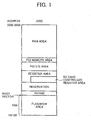
- Flash-ROM is mapped to a memory in an ASIC installed in the image forming apparatus as shown in FIG. 1. Specifically, sixteen Mega bytes of the memory are assigned to the Flash-ROM.
- an ASIC can use a card type memory as a substitute of the Flash-ROM using a memory emulation function to map a memory of the card type memory in the ASIC.
- SD Secure Digital Memory
- the SD card is ruled by a SDA to include one FAT file system, and cannot be simply used as a memory such as a Flash-ROM while omitting the FAT file system.
- an object of the present invention is to address and resolve the above-noted and other problems and provide a new card type memory, an image forming apparatus, and an image forming apparatus starting method using the card type memory that stores program arranged to efficiently use the card type memory.
- a new and noble card type memory includes a file system accessed from an ASIC included in an image forming apparatus.
- the card type memory stores, outside the file system, an operating system that starts a program installed in the image forming apparatus, an image formation program that executes image formation, and a start program that starts the image formation program.
- a region of outside said file system is mapped and is only viewable from the ASIC.
- a card type memory stores, outside the file system, a rescue operating system that starts a rescue program installed in the image forming apparatus to recover program used in the image forming apparatus, and a rescue start program that starts the rescue program.
- a region of outside said file system is mapped and is only viewable from the ASIC.
- the card type memory further stores, outside the file system, an operating system for operating program installed in the image forming apparatus, an image formation program for executing image formation, and a start program for starting the image formation program.
- the card type memory further stores, inside the file system, an operating system for operating program installed in the image forming apparatus, an image formation program for executing image formation, and a start program for starting the image formation program.
- the card type memory further stores a boot loader program for starting the image forming apparatus.
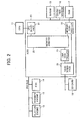
- FIG. 2 illustrates an exemplary configuration of an image forming apparatus.
- an ASIC 20 a CPU 11, a plotter engine 12, a scanner engine 13, a facsimile control unit (FCU) 14, a SD card 10, a non-volatile RAM (NVRAM) 15, an operation section 16, and a RAM 17 are included in the MFP.
- FCU facsimile control unit
- NVRAM non-volatile RAM
- the ASIC 20 servers as an IC for image processing use in cooperation with hardware elements.
- the CPU 11 generally controls the MFP.
- the FCU 14 is a unit for facsimile use.
- the scanner engine 13 reads an image.
- the plotter engine 12 executes printing.
- the SD card 10 is a media having the same size as a stamp, and is recently capable of recording massive contents by one Giga bytes at maximum.
- the NVRAM 15 stores various data.
- the operation section 16 receives inputs from a user and gives a display to the user.
- the RAM 17 stores various program and data.
- the ASIC 20 is formed from a CPU interface 21, a memory arbiter 25, a memory controller 22, a direct memory access (DMA) controller 23, and a SD card interface 24.
- a CPU interface 21 a CPU interface 21, a memory arbiter 25, a memory controller 22, a direct memory access (DMA) controller 23, and a SD card interface 24.
- DMA direct memory access
- the CPU interface 21 interfaces with the CPU 11 and the ASIC 20.
- the memory controller 22 controls data communications between the RAM 17 and the ASIC 20.
- the DMA controller 23 controls data communications between the memory arbiter 25 and the SD card interface 24.
- the SD card interface 24 serves as an interface of the SD card 10.
- the SD card interface 24 is formed from a SD control circuit 26, a DMA interface 27, a RAM access interface 28, a selector 30, and a control circuit 29.
- the SD control circuit 26 directly controls the SD card and reads data therefrom and writes data thereto.
- the control circuit 29 controls the SD control circuit 26, communicates with the CPU interface, and switches the selector 30.
- the DMA interface 27 communicates with the DMA controller 23.
- the RAM access interface 28 includes a buffer and communicates with the memory controller 22.
- the selector 30 switches output and input destinations to and from the SD control circuit 26 between DMA interface 27 and the RAM access interface 28.
- the memory map 40 is a memory map of the SD card at the time of shipping thereof.
- a MBR Master Boot Record
- a Boot Sector a Boot Sector
- a FAT0 a FAT1
- a Root Directory Entry a User data area
- a range from the Boot Sector to the Root Directory Entry is represented herein after as an area A.
- a memory map 50 of a SD card includes an area 44 having sixteen Mega bytes visible from an ASIC in addition to the memory map 40. As shown, the ASIC visible area 44 is arranged between the MBR 43 and the area A41. A leading address of the area A41 corresponds to that of the User Data area 42 of the memory map 40.
- the ASIC visible area 44 is mapped to an SD card area 63 formed in the memory map 60.
- a RAM area 61, a PCI memory area, a PCI-I/O area, a register area, a reservation area, a NVRAM use area, and a SD card area 63 are illustrated in the memory map 60.
- a SD card controller register area is also provided in the register area.
- an area ranging from the PCI memory area to the NVRAM use area is represented as an area B.
- control circuit 29 determines if initialization of the SD card controller 26 is completed in step S101. If the initialization is completed, the control circuit 29 determines if the SD card is present in step S102. If the SD card is absent, the process is terminated.
- step S103 the process goes to step S103, in which an access request is waited for. If the access request is made, the control circuit 29 determines if the access request indicates a reading request in step S104. If the reading request is not indicated and the other request, such as a write request, etc., is indicated, the control circuit 29 outputs an error response, and the process returns to step S103.
- the control circuit 29 determines if it relates to the same selector region in step S107. If it relates to the same selector region, the process goes to step S110. If it does not relate to the same selector region, the control circuit 29 issues a sector read command to the SD control circuit 26 in step S107. Thus, reading starts. If it is determined that the sector read is completed in step S108, the control circuit 29 copies a buffer memory in step S109. Then, the control circuit 29 outputs a read data response in step S109, and the process goes to step S103 in which an access request is waited for.
- step S201 a buffer memory is acquired to store information read from the SD card.
- step S202 a read address is designated as a leading address from which reading starts.
- step S203 a read selector count is designated to represent a number of sectors to read starting from the read address.
- step S204 a sector read command is issued in step S204, thereby reading starts. If the sector read is completed in step S205, copying to a main memory is started in step S206.
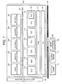
- a software of the MFP is described with reference to FIG. 7. As shown, a program group 123 of the MFP, a MFP starting section 101, and a hardware resource 125 are included.
- the MFP1 starts the program group 123 using the MFP starting section 101 in response to power supplying.
- the hardware resource 125 includes a plotter engine 12, a scanner engine 13 and other hardware resources 122.
- the other hardware resources may include an ADF, for example.
- the program group 123 is started on an operation system, such as a UNIX (TM), etc.
- an operation system such as a UNIX (TM), etc.
- Various applications such as a copier use application 102, a printer use application 103, a facsimile use application 104, a net file application 104, etc., are utilized.
- Various services such as an engine control service 110, a memory control service 111, an operation panel control service 112, a facsimile control service 113, a network control service 114, a system control service 115, etc., are executed by these applications through an API (Application Program Interface) 107.
- API Application Program Interface
- the system control service 115 includes an on-demand updating service 116.
- a process of the engine control service 110 controls an engine, such as a plotter engine 12, a scanner engine 13, etc.
- a process of the memory control service 111 executes memory control, such as obtaining and releasing a memory, usage of a HDD, etc.
- a process of the operation panel control service 112 controls an operation panel that serves as an information communications device between an operator and an apparatus.
- a process of the facsimile control service 113 provides an API that executes facsimile communications using a PSTN or an ISDN network. The process registers and quotes various facsimile data administrated in a memory for backup use, reads, receives, and prints the facsimile, or the like.
- a process of the network control service 114 provides commonly available services to applications, which use a network I/O. Specifically, the process of the NCS 114 distributes data received from the network side to respective applications using respective protocol, and mediates data transmission from the respective applications to the network side. The process of the NCS 114 controls data communications with network instruments via the network using hypertext transfer protocol daemon by means of HTTP.
- a process of the system control service 115 executes various processing, such as application administration, operation section controlling, system screen displaying, LED displaying, hardware resource administration, interruption application control, etc.
- a process of the on-demand update service 116 receives update program for updating existing program from the network.
- a process of the SRM 117 executes system control and hardware resource administration in cooperation with that of the system control service 115. For example, a process of the SRM 117 executes mediation in accordance with acquirement requests for hardware, such as a plotter engine 12, a scanner engine 13, etc., from an upper lank layer, while controlling operations.
- hardware such as a plotter engine 12, a scanner engine 13, etc.
- the process of the SRM 40 determines if a hardware resource that is requested to acquire is available, and reports availability thereof to the upper lank layer if the determination is positive.
- the process also schedules usage of the hardware resource of the acquirement requests from the upper lank layer, and directly corresponds to requests, such as paper transportation and image formation executed by a printer engine, memory reservation, file generation, etc.
- FIG. 8 a software of a rescue system is described with reference to FIG. 8.
- a program group 124 in FIG. 8 an application does not yet start in the software configuration. Remaining portions are substantially the same as those in FIG. 7.
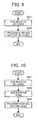
- FIG. 9 illustrates a conventional sequence in a mapping mode.
- a ROM monitor loaded in the SD card operates the MFP.
- the ROM monitor serves as a program that loads and executes an operation system.
- a phrase "ROM monitor (a SD card)" used in step S301 represents that the ROM monitor is loaded in the SD card. The same applies to a phrase " ROM monitor (a RAM)".
- step S302 a program start section loaded in the SD card operates the MFP in a similar manner to the above.
- a program loaded in the conventional SD card runs in a mapping mode. Since a processing speed is slow in the mapping mode, a program is loaded in a RAM and runs in accordance with a start sequence as shown in FIG. 10. Specifically, in step S401, when the MFP is operated by a ROM monitor loaded in the SD card in a similar manner as mentioned above, the MPF monitor is copied into the RAM.
- the MFP is operated by the RAM monitor copied in step S402, and is operated by the program start section loaded in the RAM in step S403.
- the start sequence can be executed at high speed.
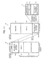
- a MFP/printer system A71 serving as a program is arranged between a MBR 43 and an area A41 in a memory map 50, and is mapped to a SD card area of the ASIC as indicated in a memory map 60 of the ASIC.
- a MFP/printer system A71 is formed from a ROM monitor 72, an operation system 73, a program start section 74, and a MFP/printer program 75 having execution codes.
- These program start section 74 and MFP/printer program 75 can be formed from a file system different from that of the SD card.
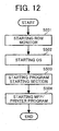
- a start sequence is described with reference to FIG. 12 when a SD card has program arrangement as illustrated in FIG. 11.
- a ROM monitor starts in step S501.
- An operation system starts in step S502.
- a program start section starts in step S503.
- a MFP/printer program starts in step S504.
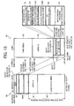
- a memory map in which the MFP/printer system is arranged outside a file system, is described with reference to FIG. 13.
- a MFP/printer system B81 as a program is arranged between a MBR 43 and an area A41 in the memory map 50.
- the MFP/printer system B81 is mapped to a SD card area of an ASIC as shown in the memory map 60 of the ASIC. Further, the MFP/printer system B82 is loaded in a RAM area 61.
- the MFP/printer system B81 is formed from a ROM monitor 72, a RAM monitor 83, an operation system 84, a program start section 85, and a MFP/printer program 86.
- the ROM monitor includes an execution code, and the others include RAM execution codes.
- a difference between a RAM execution code and an execution code is as follows:
- the latter code can be executed as is, while the former code is designed to be executed at a prescribed RAM address, and thus needs rearrangement of the code to the prescribed RAM address.
- respective codes of the RAM monitor, the operation system 84, the program start section 85, and the MFP/printer program 86 can be compressed, and respective RAM execution codes can be decoded when loaded in the RAM area 61.
- the program start section 85 and the MFP/printer program 86 can be a file image.
- the program start section 89 and the MFP/printer program 90 can be file systems. When a file system is implemented on the operation system 88, a file system region of the SD card can be accessed.
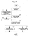
- a ROM monitor starts in step S601.
- a RAM execution code of a MFP/printer system is loaded in a RAM area in step S602.
- a RAM monitor loaded in a RAM area starts in step S603.
- An operation system, a program starting section, and a MFP/printer program start in steps S604, S605, and S606, respectively, while similarly being loaded in a RAM area.
- the SD card (the file system) is mounted in step S607.
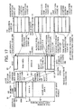
- a first memory map in which a MFP/printer program and a rescue system are arranged outside a file system, is described with reference to FIG. 15.
- the MFP/printer program and the rescue system are generally difficult to delete because of existing the outside the file system (herein below the same whenever program exists the outside).
- the rescue system serves as a program capable of executing recovery when rewriting of an update program results in failure.
- a boot selector 91, a rescue system A92, and a MFP/printer system C93 are arranged between a MBR 43 and an area A41 in a memory map 50.
- the boot selector 91, the rescue system A92, and the MFP/printer system C93 are mapped to a SD card area of the ASIC as shown in the memory map 60 of the ASIC.
- the boot selector 91 serves as a ROM monitor 72 including a program that selectively uses a rescue system.
- the rescue system A92 is formed from a rescue operation system 301, a rescue program starting section 202, and a rescue program 203 each having an execution code.
- the MFP/printer system C93 is formed from an operation system 88, a program start section 89, a MFP/printer program 90, each having an execution code.
- the rescue program start section 202, the rescue program 203, the program start section 89, and the MFP/printer program 90 can be administrated by a different file system from that of the SD card.
- a ROM monitor starts in step S701.
- a NVRAM is checked, i.e., a rescue flag is checked in step S702.
- the rescue flag represents if rewriting of an update program results in failure.
- the rescue flag is present when the rewriting is not completed and ends by some reason, for example.
- step S702 If the checking result in step S702 is negative (i.e., a rescue flag is absent), a normal operation system (i.e., not rescue system) starts in step S703. Subsequently, a normal program start section starts in step S704. A MFP/printer program starts in step S705.
- a rescue operation system starts in step S706. Subsequently, a rescue program start section starts in step S707. A rescue program starts in the next step S708.
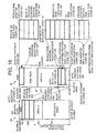
- FIG. 17 illustrates conditions in which a boot selector loaded in a SD card area of the ASIC drives a rescue system, and the rescue system causes a MFP/printer system to be loaded in a RAM area.
- a boot selector 91, a rescue system B204, and a MFP/printer system D205 are arranged between a MBR 43 and an area A41 in a memory map 50.
- the boot selector 91, the rescue system B204, and the MFP/printer system D205 are mapped to a SD card area of the ASIC as shown in the memory map 60.
- the rescue system B204 is formed from a rescue RAM monitor 210, a rescue operation system 207, a rescue program start section 208, and a rescue program 209. These programs include RAM execution codes. Thus, files of those can be compressed.
- the MFP/printer system D205 is formed from a RAM monitor 83, an operation system 84, a program start section 85, and a MFP/printer program 86. These programs also include RAM execution codes. Thus, files of those can also be compressed.
- the rescue OS 207, the rescue program start section 208, the rescue program 209, the operation system 84, the program start section 85, and the MFP/printer program 86 can be an image of a combined file system. If a file system is implemented on the operation system 88, a file system region of the SD card can be accessed.
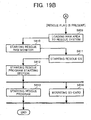
- FIG. 18 execution of a rescue system in a third memory map, in which a MFP/printer program and a rescue system are arranged outside a file system, is described with reference to FIG. 18.
- a boot selector loaded in a SD card area of an ASIC causes a rescue system to be loaded in a RAM area.
- the rescue system B220 is loaded in the RAM area 61.
- the loaded rescue system B220 is formed from a rescue RAM monitor 221, a rescue operation system 222, a rescue program start section 223, and a rescue program 224.
- a file system of the SD card can be accessed if a file system is implemented on the operation system 88 in the example of FIG. 18.
- a ROM monitor starts in step S801.
- a NVRAM is checked in step S802.
- a rescue flag is absent as a result of the check in step S802
- a MFP/printer system is loaded in a RAM area in step S803.
- a normal RAM monitor starts in the next step S804.
- a normal operation system subsequently starts in step S805.
- a normal program start section starts in the next step S804.
- a MFP/printer program starts in step S807, and a SD card is mounted in step S808.
- step S802 If the determination in step S802 is positive (i.e., a rescue flag is present), a rescue system is loaded in the RAM area in step S809. A rescue RAM monitor starts in the next step S810. A rescue operation system starts in the next step S811. A rescue program start section subsequently starts in step S812. Thus, a rescue program starts in step S813, and the SD card is mounted in step S814.
- a boot selector 91 and a rescue system A92 are arranged between a MBR 43 and an area A41 in a memory map 50 of a SD card. These boot selector 91 and rescue system A92 are mapped to the SD card area of the ASIC as shown in the memory map 60.
- a file 207 of the MFP/printer system D is loaded in a file system as shown in the memory map 50.
- the file 207 of the MFP/printer system D can be an image such that a RAM monitor, an operation system, a program start section, and a MFP/printer program collectively form a combined file system.
- the file 207 is loaded in the RAM area 61 as a MFP/printer system D206 as shown in a memory map 60.
- a boot selector 91 loaded in the SD card area of the ASIC executes such loading.
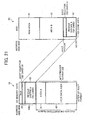
- FIG. 21 Similar to the example of FIG. 20, a memory map is illustrated, in which a MFP/printer program is arranged in the file system, and a rescue system is arranged outside the file system. A rescue system is executed in this situation as follows:
- a boot selector 91 and a rescue system A92 are arranged between an area A41 and a MBR 43 in a memory map 50.
- a MFP/printer system 208 is loaded in the file system.
- the boot selector 91 and the rescue system A92 are mapped to a SD card area of the ASIC as shown in the memory map 60.
- the boot selector 91 thus mapped starts the rescue system A92.
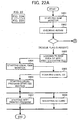
- a start sequence is described with reference to FIG. 22 when the SD card has program arrangement as illustrated in FIGS. 20 and 21.
- a ROM monitor starts in step S901.
- a NVRAM is checked in the next step S902.
- step S902 If the checking results in negative in step S902, a file of a MFP/printer system is loaded in a RAM area in step S903.
- a normal RAM monitor starts in the next step S904.
- a normal operation system subsequently starts in step S905.
- a normal program start section starts in the next step S906.
- a MFP/printer program starts in step S907.
- a SD card is mounted in step S908.
- step S902 if the checking result is positive (i.e., a rescue flag is present) in step S902, a rescue operation system starts in step S909. A rescue program start section starts in the next step S910. A rescue program starts in the next step S911.
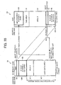
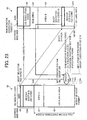
- a boot selector loaded in a SD card area of an ASIC drives a rescue system, and the rescue system causes a RAM monitor and an operation system to be loaded in a RAM area.
- a boot selector 91 and a rescue system B204 are arranged between a MBR 43 and an area A41 in a memory map 50.
- the boot selector 91, the rescue system B204, and the MFP/printer system D205 are mapped to a SD card area of the ASIC as shown in the memory map 60.
- a MFP/printer system file group 209 including a MFP/printer program group 210 is loaded in the file system.
- the mapped boot selector 91 causes the RAM monitor and the operation system of the MFP/printer system group 209 to be loaded in the RAM area 61 of the ASIC as a RAM monitor 87 and an operation system 88, and executes those.
- step S1002 If the checking result in step S1002 is negative, a RAM monitor and a normal operation system expand in the RAM area in step S1003. A normal RAM monitor starts in the next step S1004. A normal operation system subsequently starts in step S1005. The SD card is mounted in the next step S1006.
- a file of the normal program start section starts in step S1007.
- a MFP/printer program starts in step S1008.
- step S1002 If the checking result in step S1002 is positive, a rescue operation system starts in step S1010. A rescue program start section starts in the next step S1011. A rescue program starts in the next step S1012.
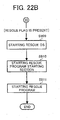
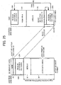
- a rescue system in a memory map in which a MFP/printer system is arranged within a file system and a rescue system is arranged outside the file system, is described with reference to FIG. 25.
- a boot selector loaded in a SD card area of an ASIC causes a rescue system to be loaded in a RAM area.
- a boot selector 91 and a rescue system B204 are arranged between a MBR 43 and an area A41 in the memory map 50 of the SD card. These boot selector 91 and rescue system B204 are mapped to the SD card area of the ASIC as shown in the memory map 60 of the ASIC.
- a MFP/printer system 208 is loaded in the file system shown in the memory map 50.
- the mapped boot selector 91 causes the rescue system B204 to be loaded in the RAM area 61 of the ASIC, and executes those.
- a start sequence executed when a SD card has program arrangement as illustrated in FIG. 25 is similar to that as illustrated in FIG. 19.
- the MFP/printer program corresponds the image formation program.
- the program start section corresponds to the start program.
- the rescue program start section corresponds the start rescue program.
- the ROM monitor, the RAM monitor, and the boot selector collectively correspond to the boot loader program.
- the SD card area corresponds to a first memory device.
- the RAM area and the memory collectively correspond to the second memory device.
- the file system-mounting device corresponds to the CPU.
- the processing program corresponds to the MFP/printer system.
- the rescue system corresponds to the recovery program.
- the ROM monitor mapped to the SD card area corresponds to a first boot loader program.
- the RAM monitor loaded in the RAM area corresponds to a second boot loader program.
- Step S501 corresponds to the boot loader start step.
- Step S502 corresponds to the operation system start step.
- Step S504 corresponds to the image formation program start step.
- Step S702 corresponds to the rescue flag check step.
- Step S803 corresponds to the processing program expansion step.
- Step S808 corresponds to the file system mount step.
Landscapes
- Engineering & Computer Science (AREA)
- Software Systems (AREA)
- Theoretical Computer Science (AREA)
- Computer Security & Cryptography (AREA)
- Physics & Mathematics (AREA)
- General Engineering & Computer Science (AREA)
- General Physics & Mathematics (AREA)
- Stored Programmes (AREA)
- Facsimiles In General (AREA)
- Record Information Processing For Printing (AREA)
- Control Or Security For Electrophotography (AREA)
Applications Claiming Priority (1)
| Application Number | Priority Date | Filing Date | Title |
|---|---|---|---|
| JP2004158118A JP4695348B2 (ja) | 2004-05-27 | 2004-05-27 | カード型メモリ、画像形成装置、画像形成装置起動方法 |
Publications (1)
| Publication Number | Publication Date |
|---|---|
| EP1622010A1 true EP1622010A1 (en) | 2006-02-01 |
Family
ID=35169429
Family Applications (1)
| Application Number | Title | Priority Date | Filing Date |
|---|---|---|---|
| EP05011103A Ceased EP1622010A1 (en) | 2004-05-27 | 2005-05-23 | Card type memory, image forming apparatus, and method of starting the apparatus using the card |
Country Status (3)
| Country | Link |
|---|---|
| US (1) | US7715028B2 (enExample) |
| EP (1) | EP1622010A1 (enExample) |
| JP (1) | JP4695348B2 (enExample) |
Families Citing this family (11)
| Publication number | Priority date | Publication date | Assignee | Title |
|---|---|---|---|---|
| US7739487B2 (en) * | 2006-01-17 | 2010-06-15 | Nokia Corporation | Method for booting a host device from an MMC/SD device, a host device bootable from an MMC/SD device and an MMC/SD device method a host device may booted from |
| US8570583B2 (en) * | 2006-11-06 | 2013-10-29 | Ricoh Company, Ltd. | Method for controlling an image forming apparatus using information from a detachable recording medium |
| JP5707870B2 (ja) * | 2010-11-02 | 2015-04-30 | 富士ゼロックス株式会社 | 情報処理装置及び記憶媒体 |
| CN104063234B (zh) * | 2013-03-19 | 2017-06-27 | 华为技术有限公司 | 一种兼容方法及装置 |
| JP6064755B2 (ja) * | 2013-04-10 | 2017-01-25 | 富士ゼロックス株式会社 | 電子機器、画像形成装置、制御装置及びプログラム |
| JP6264896B2 (ja) * | 2014-01-16 | 2018-01-24 | 株式会社リコー | 情報処理装置、制御方法及び制御プログラム |
| US9823846B2 (en) | 2014-08-20 | 2017-11-21 | Qualcomm Incorporated | Systems and methods for expanding memory for a system on chip |
| JP6090261B2 (ja) * | 2014-08-20 | 2017-03-08 | コニカミノルタ株式会社 | 画像形成装置、起動制御方法および起動制御プログラム |
| US10616433B2 (en) * | 2015-01-27 | 2020-04-07 | Brother Kogyo Kabushiki Kaisha | Image processing device |
| KR101822253B1 (ko) * | 2015-02-04 | 2018-01-25 | 주식회사 엘지화학 | 점착제 조성물 |
| JP7790213B2 (ja) * | 2022-03-07 | 2025-12-23 | ブラザー工業株式会社 | 画像形成システム、及び画像形成装置 |
Citations (2)
| Publication number | Priority date | Publication date | Assignee | Title |
|---|---|---|---|---|
| WO2001040946A1 (en) * | 1999-12-01 | 2001-06-07 | Microsoft Corporation | Automated recovery of computer appliances |
| US20010034821A1 (en) * | 2000-04-19 | 2001-10-25 | Yung-Chi Hwang | Program-downloadable data processing system and method for accessing memory by using a unified memory space therein |
Family Cites Families (9)
| Publication number | Priority date | Publication date | Assignee | Title |
|---|---|---|---|---|
| JPH06324857A (ja) * | 1993-05-13 | 1994-11-25 | Toshiba Corp | コンピュータシステム |
| US6381694B1 (en) | 1994-02-18 | 2002-04-30 | Apple Computer, Inc. | System for automatic recovery from software problems that cause computer failure |
| JP3667958B2 (ja) * | 1997-10-09 | 2005-07-06 | 東芝テック株式会社 | 情報処理装置 |
| US6715067B1 (en) * | 1999-09-21 | 2004-03-30 | Intel Corporation | Initializing a processor-based system from a non-volatile re-programmable semiconductor memory |
| JP2002312212A (ja) * | 2001-04-13 | 2002-10-25 | Toshiba Corp | ファイルシステム |
| JP4121333B2 (ja) | 2001-08-27 | 2008-07-23 | 株式会社リコー | 画像形成装置,プログラム更新方法および記録媒体 |
| JP4083505B2 (ja) | 2001-08-27 | 2008-04-30 | 株式会社リコー | 画像形成装置,プログラム更新方法および記録媒体 |
| US20030231343A1 (en) * | 2002-05-08 | 2003-12-18 | Ayako Kobayashi | Image forming apparatus, program adding method, and a recording medium |
| US7644288B2 (en) | 2003-03-19 | 2010-01-05 | Ricoh Company, Ltd. | Image forming apparauts that checks authenticity of an update program |
-
2004
- 2004-05-27 JP JP2004158118A patent/JP4695348B2/ja not_active Expired - Fee Related
-
2005
- 2005-05-23 EP EP05011103A patent/EP1622010A1/en not_active Ceased
- 2005-05-26 US US11/137,651 patent/US7715028B2/en not_active Expired - Fee Related
Patent Citations (2)
| Publication number | Priority date | Publication date | Assignee | Title |
|---|---|---|---|---|
| WO2001040946A1 (en) * | 1999-12-01 | 2001-06-07 | Microsoft Corporation | Automated recovery of computer appliances |
| US20010034821A1 (en) * | 2000-04-19 | 2001-10-25 | Yung-Chi Hwang | Program-downloadable data processing system and method for accessing memory by using a unified memory space therein |
Non-Patent Citations (3)
| Title |
|---|
| "Concept of SPB-Linux-2", WWW.8UNG.AT, 24 March 2003 (2003-03-24), XP002904340 * |
| "MEMORY CARD PROVIDES BOOT MEMORY FOR BOOT-UP OPERATION", RESEARCH DISCLOSURE, MASON PUBLICATIONS, HAMPSHIRE, GB, no. 326, 1 June 1991 (1991-06-01), pages 427, XP000206605, ISSN: 0374-4353 * |
| ANONYMOUS: "Booting", WIKIPEDIA.ORG, vol. -, 13 May 2004 (2004-05-13), pages 1 - 2, XP002355021, Retrieved from the Internet <URL:http://en.wikipedia.org/w/index.php?title=Booting&oldid=3759952&printable=yes> * |
Also Published As
| Publication number | Publication date |
|---|---|
| US7715028B2 (en) | 2010-05-11 |
| JP4695348B2 (ja) | 2011-06-08 |
| JP2005339271A (ja) | 2005-12-08 |
| US20060001909A1 (en) | 2006-01-05 |
Similar Documents
| Publication | Publication Date | Title |
|---|---|---|
| US7380243B2 (en) | Image forming apparatus of which programs are remotely updatable | |
| EP1387566B1 (en) | Image forming apparatus | |
| JP4200067B2 (ja) | 画像処理装置、画像処理方法、及び画像処理プログラム | |
| EP1622010A1 (en) | Card type memory, image forming apparatus, and method of starting the apparatus using the card | |
| JP2012059024A (ja) | 情報処理装置、起動制御方法、起動制御プログラム及び記録媒体 | |
| US20190265964A1 (en) | Electronic apparatus, updating method, and recording medium | |
| JP6875808B2 (ja) | 情報処理装置 | |
| US7302578B2 (en) | Information processing apparatus, image forming apparatus, program-initiation error processing method, and recording medium | |
| EP1308793B1 (en) | Image forming device having a memory assignment unit | |
| JP4001531B2 (ja) | 画像形成装置 | |
| US20050231756A1 (en) | Image forming apparatus | |
| JP4856622B2 (ja) | 画像形成装置、プログラム更新方法 | |
| US10484571B2 (en) | Multifunction device, reboot method, and non-transitory recording medium storing computer readable program | |
| JP2018063676A (ja) | 情報処理装置及びその制御方法、並びにプログラム | |
| JP6929160B2 (ja) | 画像形成装置およびその制御方法とプログラム | |
| JP4480779B2 (ja) | 画像処理装置、画像処理装置の動作方法及びプログラム | |
| JP2005028687A (ja) | 画像処理装置,情報処理装置およびメモリディスク管理方法 | |
| KR20240046851A (ko) | 화상 형성 장치, 화상 형성 장치의 제어 방법 및 저장 매체 | |
| JP6489827B2 (ja) | 画像処理装置、画像処理装置の制御方法及びプログラム | |
| JP4124410B2 (ja) | メモリ書換え方法およびその方法をコンピュータに実行させるためのプログラム | |
| JP4128467B2 (ja) | 画像形成装置及びメモリマップ方法 | |
| JP4128468B2 (ja) | 情報処理装置及びメモリマップ方法 | |
| JP2000326592A (ja) | 画像入出力装置 | |
| JP2007295371A (ja) | 画像形成装置及びコンピュータプログラム | |
| JP4246608B2 (ja) | 画像形成装置及びプログラム起動方法 |
Legal Events
| Date | Code | Title | Description |
|---|---|---|---|
| PUAI | Public reference made under article 153(3) epc to a published international application that has entered the european phase |
Free format text: ORIGINAL CODE: 0009012 |
|
| AK | Designated contracting states |
Kind code of ref document: A1 Designated state(s): AT BE BG CH CY CZ DE DK EE ES FI FR GB GR HU IE IS IT LI LT LU MC NL PL PT RO SE SI SK TR |
|
| AX | Request for extension of the european patent |
Extension state: AL BA HR LV MK YU |
|
| 17P | Request for examination filed |
Effective date: 20060413 |
|
| 17Q | First examination report despatched |
Effective date: 20060831 |
|
| AKX | Designation fees paid |
Designated state(s): DE ES FR GB IT NL |
|
| STAA | Information on the status of an ep patent application or granted ep patent |
Free format text: STATUS: THE APPLICATION HAS BEEN REFUSED |
|
| 18R | Application refused |
Effective date: 20091214 |