EP1621826A1 - Ensemble de chauffage avec un élément CTP, notamment pour un véhicule automobile - Google Patents
Ensemble de chauffage avec un élément CTP, notamment pour un véhicule automobile Download PDFInfo
- Publication number
- EP1621826A1 EP1621826A1 EP04291929A EP04291929A EP1621826A1 EP 1621826 A1 EP1621826 A1 EP 1621826A1 EP 04291929 A EP04291929 A EP 04291929A EP 04291929 A EP04291929 A EP 04291929A EP 1621826 A1 EP1621826 A1 EP 1621826A1
- Authority
- EP
- European Patent Office
- Prior art keywords
- heating
- heating arrangement
- arrangement according
- frame
- contact
- Prior art date
- Legal status (The legal status is an assumption and is not a legal conclusion. Google has not performed a legal analysis and makes no representation as to the accuracy of the status listed.)
- Granted
Links
Images


Classifications
-
- F—MECHANICAL ENGINEERING; LIGHTING; HEATING; WEAPONS; BLASTING
- F24—HEATING; RANGES; VENTILATING
- F24H—FLUID HEATERS, e.g. WATER OR AIR HEATERS, HAVING HEAT-GENERATING MEANS, e.g. HEAT PUMPS, IN GENERAL
- F24H9/00—Details
- F24H9/18—Arrangement or mounting of grates or heating means
- F24H9/1854—Arrangement or mounting of grates or heating means for air heaters
- F24H9/1863—Arrangement or mounting of electric heating means
-
- B—PERFORMING OPERATIONS; TRANSPORTING
- B60—VEHICLES IN GENERAL
- B60H—ARRANGEMENTS OF HEATING, COOLING, VENTILATING OR OTHER AIR-TREATING DEVICES SPECIALLY ADAPTED FOR PASSENGER OR GOODS SPACES OF VEHICLES
- B60H1/00—Heating, cooling or ventilating [HVAC] devices
- B60H1/22—Heating, cooling or ventilating [HVAC] devices the heat being derived otherwise than from the propulsion plant
- B60H1/2215—Heating, cooling or ventilating [HVAC] devices the heat being derived otherwise than from the propulsion plant the heat being derived from electric heaters
- B60H1/2225—Heating, cooling or ventilating [HVAC] devices the heat being derived otherwise than from the propulsion plant the heat being derived from electric heaters arrangements of electric heaters for heating air
-
- F—MECHANICAL ENGINEERING; LIGHTING; HEATING; WEAPONS; BLASTING
- F24—HEATING; RANGES; VENTILATING
- F24H—FLUID HEATERS, e.g. WATER OR AIR HEATERS, HAVING HEAT-GENERATING MEANS, e.g. HEAT PUMPS, IN GENERAL
- F24H3/00—Air heaters
- F24H3/02—Air heaters with forced circulation
- F24H3/04—Air heaters with forced circulation the air being in direct contact with the heating medium, e.g. electric heating element
- F24H3/0405—Air heaters with forced circulation the air being in direct contact with the heating medium, e.g. electric heating element using electric energy supply, e.g. the heating medium being a resistive element; Heating by direct contact, i.e. with resistive elements, electrodes and fins being bonded together without additional element in-between
Definitions
- the invention relates to a heating arrangement with a PTC element, in particular for a motor vehicle, according to the preamble of claim 1.
- a heating arrangement with a PTC element for passenger vehicles wherein an additional heating with a radiator, which is flowed through in the operation of the additional heating of heating air, and provided with at least one air outlet opening in the foot of a passenger compartment, to the the heating air is passed.
- the radiator is designed as an electric PTC element, which is arranged directly on the air outlet opening in the foot region.
- a PTC element is arranged in the form of several Schuwaben in a plastic frame not described in detail, which encloses the air outlet opening.
- a heating arrangement in particular for a motor vehicle, with a plurality of electrical heating elements, in particular PTC elements, which are part of heating strands, which are each formed by an assembly, each heating strand at least one electric heating element, in particular PTC element, two From the outside electrically contacted contact plates and two corrugated fins, and two adjacent modules mirror image or the same design and mirror image and / or are arranged the same.
- the subassemblies which are preferably identical or at least with the same subassemblies for different heating arrangements, can be produced in large numbers, the production costs can be reduced and the logistics simplified.
- a plurality of identical parts are used, which may be assembled differently, it is possible to optimize variants, i. the position of the PTC elements can be adapted to the requirements, i. to the course of the air flow, optimally adapted.
- Each assembly preferably has at least two contact plates on which a contact element is attached laterally, which serves for electrical contacting.
- the contact plates which are connected to the contact elements, the same design as the other contact plates of the assembly.
- spring tongues are preferably provided to improve the electrical contact.
- the assembly preferably has at least two corrugated fins, which are arranged on the outside of two contact plates between which a PTC element is provided.
- the assembly can be extended by one, two or optionally more corrugated fins, wherein preferably a contact plate is provided between two corrugated fins. This allows a relatively variable design of the width of the module with identical structure of the core area.
- the heating arrangement may include both jointly controlled and, in particular in the case of multi-zone air conditioning systems, independently controlled heating strands.
- the assemblies are preferably placed in a frame, in particular in an injection-molded plastic frame.
- the frame is preferably designed in several parts.
- the individual frame elements are preferably connected to each other by means of clip connections, whereby a very simple and quick installation without tools is possible.
- the frame preferably has a transverse strut serving as a partition wall, which spatially and / or thermally or electrically separates two adjacent assemblies from one another.
- the transverse strut is preferably arranged in a plane of symmetry of the frame.
- a second transverse strut is preferably provided perpendicular to a first transverse strut extending parallel to the assemblies for separating the air streams.
- this preferably only extends as far as the assemblies and not between them.
- the electrical contacting of the contact elements is preferably carried out by means of a laterally provided on the frame cover, which forms a part of the frame. This is preferably also secured by means of clip connections. On the outside of the cover plugs are preferably provided.
- the electrical control and the contacting of the contact elements can be done in any way.
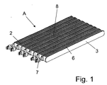
- a PTC heater assembly 1 which is arranged as a heater in a four-zone automotive air conditioning system in the air flow direction according to a conventional heater is formed according to the first embodiment by two modules which are arranged in mirror image (in Fig. 2 denoted by A and B) ,
- Each of the assemblies A and B consists of a plurality of ceramic PTC elements 2, contact plates 3 and corrugated fins 6.
- a ceramic PTC element 2 is glued between two mutually parallel contact plates 3, in this case by means of an electrically conductive adhesive (not shown ). Alternatively, for example, a solder connection may be provided.
- an electrically conductive adhesive not shown
- a solder connection may be provided on each of the PTC element 2 opposite sides of the contact plates 3 corrugated ribs 6 are attached by means of a corresponding adhesive compound, which in turn are connected on the side facing away from the PTC element 2 side with a further contact plate 3.
- PTC elements 2 are provided, which are each arranged between two contact plates 3, which in turn are separated from corrugated fins 6, wherein in part only between two corrugated fins 6, a contact plate 3 without PTC element 2 is provided.
- Various contact plates 3 are formed extended on one side by attaching a contact element 7, so that they serve the electrical contact.
- one PTC element 2 is provided between each two extended contact plates 3.
- one or two corrugated ribs 6 and one or two non-extended contact plates 3 are provided between each two extended contact plates 3.
- Each of the assemblies A and B forms, due to the common electrical contacting of the individual PTC elements of each module A and B a mutually independently controlled heating train 8.
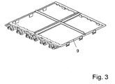
- a two-part plastic frame 9, in this case made of polyamide, is arranged around the heating arrangement 1 described above, with the two frame elements being connected to one another by means of clip connections.
- the two heating strands 8 are inserted into the lower frame member, as shown in Fig. 2, wherein they are spaced from each other.
- the upper frame member which is shown in Fig. 3 as a single part, placed and the two frame members by squeezing connected as a result of the engagement of the clip connections. This condition is shown in FIG.
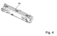
- the contact elements 7 project with their outer ends beyond the frame 9. At these ends are corresponding contact rails, which are provided in a side cover 10, shown in Fig. 4, the plastic frame 9, and allow a common electrical contacting of the individual heating strands 8.
- 7 spring tongues are provided on the contact elements (see Fig. 1).
- the cover 10 is attached laterally and held by means of further clip connections to the two frame elements. The fully assembled state is shown in FIG.
- the individual heating strands 8 can serve as standard elements, which can be used in different frames 9, whereby the manufacturing costs are reduced.
- the two heating strands 8 are identical, but one of the heating strands 8 is installed rotated by 180 °.
- Each assembly consists of subassemblies, so that the manufacturing costs can be further reduced.
- At least the upper of the frame members has crossed struts arranged crosswise (see Fig. 3), which serve for the division of the air flow (four-zone air conditioning).
- the transverse strut extending in the longitudinal direction of the PTC elements 2 serves, on the one hand, to stabilize and, on the other hand, to spatially separate the two heating strands 8. Since the same polarity is applied to the adjacent contact plates 3 arranged centrally in the frame 9 because of the symmetry, this is a short circuit locked out. In this case, two zones of the air conditioner are coupled together due to the presence of only two heating strands 8, ie the driver-side air conditioning of front and rear as well as the passenger-side air conditioning of front and rear are coupled together.
- the transverse strut arranged perpendicularly to the PTC elements can be dispensed with, so that the air flow in this area is not hindered.
- the structure may be identical or, for example, as described below with reference to the second embodiment.
- Fig. 7 shows the two modules A and B, each consisting of a heating element 8, for a heating element 1 according to the second embodiment.
- this heating element 1 is provided in particular for a two-zone air conditioning system.
- it can also be used for a single-tone air conditioner or possibly a multi-zone air conditioner.
- each of the assemblies A and B in contrast to the first embodiment, five contact elements 7 are provided per module.
- the design of the two assemblies A and B are identical, but one of the assemblies A and B is rotated by 180 ° in the frame 9.
- Each of the assemblies A and B in turn has subassemblies.
Landscapes
- Engineering & Computer Science (AREA)
- Physics & Mathematics (AREA)
- Thermal Sciences (AREA)
- Mechanical Engineering (AREA)
- Chemical & Material Sciences (AREA)
- Combustion & Propulsion (AREA)
- General Engineering & Computer Science (AREA)
- Air-Conditioning For Vehicles (AREA)
- Resistance Heating (AREA)
Priority Applications (2)
| Application Number | Priority Date | Filing Date | Title |
|---|---|---|---|
| EP20040291929 EP1621826B1 (fr) | 2004-07-27 | 2004-07-27 | Ensemble de chauffage avec un élément CTP, notamment pour un véhicule automobile |
| PCT/EP2005/007184 WO2006010436A1 (fr) | 2004-07-27 | 2005-07-04 | Systeme de chauffage a element a coefficient de temperature positif, notamment pour un vehicule automobile |
Applications Claiming Priority (1)
| Application Number | Priority Date | Filing Date | Title |
|---|---|---|---|
| EP20040291929 EP1621826B1 (fr) | 2004-07-27 | 2004-07-27 | Ensemble de chauffage avec un élément CTP, notamment pour un véhicule automobile |
Publications (2)
| Publication Number | Publication Date |
|---|---|
| EP1621826A1 true EP1621826A1 (fr) | 2006-02-01 |
| EP1621826B1 EP1621826B1 (fr) | 2014-09-10 |
Family
ID=34931299
Family Applications (1)
| Application Number | Title | Priority Date | Filing Date |
|---|---|---|---|
| EP20040291929 Expired - Fee Related EP1621826B1 (fr) | 2004-07-27 | 2004-07-27 | Ensemble de chauffage avec un élément CTP, notamment pour un véhicule automobile |
Country Status (2)
| Country | Link |
|---|---|
| EP (1) | EP1621826B1 (fr) |
| WO (1) | WO2006010436A1 (fr) |
Cited By (4)
| Publication number | Priority date | Publication date | Assignee | Title |
|---|---|---|---|---|
| EP2131117A1 (fr) * | 2008-06-04 | 2009-12-09 | Behr France Rouffach SAS | Climatisation de véhicule automobile dotée d'un dispositif de chauffage ptc |
| EP2133225A1 (fr) * | 2008-06-11 | 2009-12-16 | Behr France Rouffach SAS | Dispositif destiné au chauffage électrique sur un système de chauffage d'un véhicule automobile, cadre d'un dispositif électrique destiné au chauffage sur un système de chauffage et procédé de fabrication d'un cadre destiné à la réception d'un élément de chauffe électrique |
| US20150108117A1 (en) * | 2013-10-21 | 2015-04-23 | MAHLE Behr France Rouffach S.A.S. | Heater |
| FR3083746A1 (fr) * | 2018-07-13 | 2020-01-17 | Valeo Systemes Thermiques | Dispositif de chauffage electrique pour vehicule automobile |
Families Citing this family (1)
| Publication number | Priority date | Publication date | Assignee | Title |
|---|---|---|---|---|
| DE102010019777B4 (de) | 2010-05-07 | 2019-08-22 | Airbus Operations Gmbh | Luftfahrzeug mit einem Fluidleitungssystem |
Citations (5)
| Publication number | Priority date | Publication date | Assignee | Title |
|---|---|---|---|---|
| DE9407104U1 (de) * | 1994-04-29 | 1994-10-13 | Sunlead Electrical Corp | Heizvorrichtung |
| US5562844A (en) * | 1992-06-23 | 1996-10-08 | David & Baader - Dbk- Spezialfabrik Elektrischer Apparate Und Heizwiderstande Gmbh | Ptc heater radiator with frame members applying pressure to heaters |
| US6124570A (en) | 1998-02-20 | 2000-09-26 | Micro Compact Car Ag | Heating and air conditioning system for vehicles |
| DE10144757A1 (de) | 2001-09-11 | 2003-03-27 | Webasto Thermosysteme Gmbh | Zusatzheizung für Personenfahrzeuge |
| EP1327834A1 (fr) * | 2002-01-15 | 2003-07-16 | David + Baader GmbH | Elément de radiation pour appareil de chauffage |
-
2004
- 2004-07-27 EP EP20040291929 patent/EP1621826B1/fr not_active Expired - Fee Related
-
2005
- 2005-07-04 WO PCT/EP2005/007184 patent/WO2006010436A1/fr active Application Filing
Patent Citations (5)
| Publication number | Priority date | Publication date | Assignee | Title |
|---|---|---|---|---|
| US5562844A (en) * | 1992-06-23 | 1996-10-08 | David & Baader - Dbk- Spezialfabrik Elektrischer Apparate Und Heizwiderstande Gmbh | Ptc heater radiator with frame members applying pressure to heaters |
| DE9407104U1 (de) * | 1994-04-29 | 1994-10-13 | Sunlead Electrical Corp | Heizvorrichtung |
| US6124570A (en) | 1998-02-20 | 2000-09-26 | Micro Compact Car Ag | Heating and air conditioning system for vehicles |
| DE10144757A1 (de) | 2001-09-11 | 2003-03-27 | Webasto Thermosysteme Gmbh | Zusatzheizung für Personenfahrzeuge |
| EP1327834A1 (fr) * | 2002-01-15 | 2003-07-16 | David + Baader GmbH | Elément de radiation pour appareil de chauffage |
Cited By (5)
| Publication number | Priority date | Publication date | Assignee | Title |
|---|---|---|---|---|
| EP2131117A1 (fr) * | 2008-06-04 | 2009-12-09 | Behr France Rouffach SAS | Climatisation de véhicule automobile dotée d'un dispositif de chauffage ptc |
| EP2133225A1 (fr) * | 2008-06-11 | 2009-12-16 | Behr France Rouffach SAS | Dispositif destiné au chauffage électrique sur un système de chauffage d'un véhicule automobile, cadre d'un dispositif électrique destiné au chauffage sur un système de chauffage et procédé de fabrication d'un cadre destiné à la réception d'un élément de chauffe électrique |
| US20150108117A1 (en) * | 2013-10-21 | 2015-04-23 | MAHLE Behr France Rouffach S.A.S. | Heater |
| US9937772B2 (en) * | 2013-10-21 | 2018-04-10 | Mahle International Gmbh | Heater |
| FR3083746A1 (fr) * | 2018-07-13 | 2020-01-17 | Valeo Systemes Thermiques | Dispositif de chauffage electrique pour vehicule automobile |
Also Published As
| Publication number | Publication date |
|---|---|
| EP1621826B1 (fr) | 2014-09-10 |
| WO2006010436A1 (fr) | 2006-02-02 |
Similar Documents
| Publication | Publication Date | Title |
|---|---|---|
| EP1452357B1 (fr) | Appareil de chauffage électrique avec plusieurs zones de chauffage | |
| EP1780061B1 (fr) | Dispositif de chauffage électrique pour un véhicule automobile | |
| WO2006012963A1 (fr) | Dispositif de chauffage comportant un element chauffant, destine notamment a un vehicule a moteur | |
| EP1626231B1 (fr) | Dispositif de chauffage avec éléments de chauffage électriques, en particulier pour un véhicule | |
| DE19925757C5 (de) | Heizeinrichtung, insbesondere für ein Kraftfahrzeug | |
| EP1800520A1 (fr) | Systeme de chauffage electrique, notamment pour un vehicule automobile | |
| DE19957452B4 (de) | Elektrische Heizeinrichtung, insbesondere für ein Kraftfahrzeug | |
| EP1523226B1 (fr) | Ensemble de chauffage comprenant des éléments PTC, particulièrement pour véhicules à moteurs | |
| DE19933013A1 (de) | PTC-Heizelement mit Heizzonen | |
| WO2006010436A1 (fr) | Systeme de chauffage a element a coefficient de temperature positif, notamment pour un vehicule automobile | |
| EP1522439B2 (fr) | Dispositif de chauffage avec élément à coefficient positif, en particulier pour un véhicule automobile | |
| EP1926346B1 (fr) | Dispositif de chauffage électrique, en particulier de véhicules | |
| EP2145783A2 (fr) | Chauffage de véhicule | |
| EP2145782B1 (fr) | Chauffage de véhicule | |
| EP1523225B1 (fr) | Dispositif de chauffage comprenant des éléments PTC, en particulier pour véhicules à moteurs | |
| EP1691579A1 (fr) | Dispositif de chauffage électrique, en particulier pour véhicule à moteur | |
| DE102018207037A1 (de) | Elektrische Heizeinrichtung mit einem eine Rippenstruktur aufweisenden Kühlkörper | |
| EP1486363B1 (fr) | Dispositif de chauffage comprenant un élément ptc, en particulier pour véhicule | |
| EP1439738B1 (fr) | Dispositif de chauffage comprenant des éléments PTC | |
| WO2018134017A1 (fr) | Échangeur de chaleur pour véhicule ainsi qu'appareil de climatisation et procédé associé | |
| EP1340638A2 (fr) | Dispositif d'échange de chaleur | |
| EP1630488A1 (fr) | Dispositif de chauffage avec éléments de chauffage électriques, en particulier pour un véhicule | |
| EP1885159B1 (fr) | Ensemble de chauffage électrique, notamment pour véhicule automobile | |
| DE102016107035B4 (de) | Heizstab | |
| EP2360437B1 (fr) | dispositif de chauffage electrique |
Legal Events
| Date | Code | Title | Description |
|---|---|---|---|
| PUAI | Public reference made under article 153(3) epc to a published international application that has entered the european phase |
Free format text: ORIGINAL CODE: 0009012 |
|
| AK | Designated contracting states |
Kind code of ref document: A1 Designated state(s): AT BE BG CH CY CZ DE DK EE ES FI FR GB GR HU IE IT LI LU MC NL PL PT RO SE SI SK TR |
|
| AX | Request for extension of the european patent |
Extension state: AL HR LT LV MK |
|
| 17P | Request for examination filed |
Effective date: 20060801 |
|
| AKX | Designation fees paid |
Designated state(s): CZ DE ES FR IT |
|
| 17Q | First examination report despatched |
Effective date: 20061201 |
|
| GRAP | Despatch of communication of intention to grant a patent |
Free format text: ORIGINAL CODE: EPIDOSNIGR1 |
|
| INTG | Intention to grant announced |
Effective date: 20131213 |
|
| GRAP | Despatch of communication of intention to grant a patent |
Free format text: ORIGINAL CODE: EPIDOSNIGR1 |
|
| GRAS | Grant fee paid |
Free format text: ORIGINAL CODE: EPIDOSNIGR3 |
|
| INTG | Intention to grant announced |
Effective date: 20140708 |
|
| GRAA | (expected) grant |
Free format text: ORIGINAL CODE: 0009210 |
|
| AK | Designated contracting states |
Kind code of ref document: B1 Designated state(s): CZ DE ES FR IT |
|
| REG | Reference to a national code |
Ref country code: DE Ref legal event code: R081 Ref document number: 502004014712 Country of ref document: DE Owner name: MAHLE INTERNATIONAL GMBH, DE Free format text: FORMER OWNER: BEHR FRANCE ROUFFACH S.A.S., ROUFFACH, FR |
|
| REG | Reference to a national code |
Ref country code: DE Ref legal event code: R096 Ref document number: 502004014712 Country of ref document: DE Effective date: 20141016 |
|
| PG25 | Lapsed in a contracting state [announced via postgrant information from national office to epo] |
Ref country code: ES Free format text: LAPSE BECAUSE OF FAILURE TO SUBMIT A TRANSLATION OF THE DESCRIPTION OR TO PAY THE FEE WITHIN THE PRESCRIBED TIME-LIMIT Effective date: 20140910 |
|
| PG25 | Lapsed in a contracting state [announced via postgrant information from national office to epo] |
Ref country code: CZ Free format text: LAPSE BECAUSE OF FAILURE TO SUBMIT A TRANSLATION OF THE DESCRIPTION OR TO PAY THE FEE WITHIN THE PRESCRIBED TIME-LIMIT Effective date: 20140910 |
|
| REG | Reference to a national code |
Ref country code: DE Ref legal event code: R082 Ref document number: 502004014712 Country of ref document: DE Representative=s name: GRAUEL, ANDREAS, DIPL.-PHYS. DR. RER. NAT., DE Ref country code: DE Ref legal event code: R081 Ref document number: 502004014712 Country of ref document: DE Owner name: MAHLE INTERNATIONAL GMBH, DE Free format text: FORMER OWNER: BEHR FRANCE ROUFFACH SAS, ROUFFACH, FR |
|
| RAP2 | Party data changed (patent owner data changed or rights of a patent transferred) |
Owner name: MAHLE BEHR FRANCE ROUFFACH S.A.S |
|
| REG | Reference to a national code |
Ref country code: DE Ref legal event code: R097 Ref document number: 502004014712 Country of ref document: DE |
|
| REG | Reference to a national code |
Ref country code: DE Ref legal event code: R082 Ref document number: 502004014712 Country of ref document: DE Representative=s name: GRAUEL, ANDREAS, DIPL.-PHYS. DR. RER. NAT., DE Ref country code: DE Ref legal event code: R081 Ref document number: 502004014712 Country of ref document: DE Owner name: MAHLE INTERNATIONAL GMBH, DE Free format text: FORMER OWNER: MAHLE BEHR FRANCE ROUFFACH S.A.S., ROUFFACH, FR |
|
| PLBE | No opposition filed within time limit |
Free format text: ORIGINAL CODE: 0009261 |
|
| STAA | Information on the status of an ep patent application or granted ep patent |
Free format text: STATUS: NO OPPOSITION FILED WITHIN TIME LIMIT |
|
| 26N | No opposition filed |
Effective date: 20150611 |
|
| PG25 | Lapsed in a contracting state [announced via postgrant information from national office to epo] |
Ref country code: IT Free format text: LAPSE BECAUSE OF FAILURE TO SUBMIT A TRANSLATION OF THE DESCRIPTION OR TO PAY THE FEE WITHIN THE PRESCRIBED TIME-LIMIT Effective date: 20140910 |
|
| REG | Reference to a national code |
Ref country code: FR Ref legal event code: PLFP Year of fee payment: 13 |
|
| REG | Reference to a national code |
Ref country code: FR Ref legal event code: PLFP Year of fee payment: 14 |
|
| REG | Reference to a national code |
Ref country code: FR Ref legal event code: PLFP Year of fee payment: 15 |
|
| PGFP | Annual fee paid to national office [announced via postgrant information from national office to epo] |
Ref country code: FR Payment date: 20200717 Year of fee payment: 17 |
|
| PGFP | Annual fee paid to national office [announced via postgrant information from national office to epo] |
Ref country code: DE Payment date: 20210920 Year of fee payment: 18 |
|
| PG25 | Lapsed in a contracting state [announced via postgrant information from national office to epo] |
Ref country code: FR Free format text: LAPSE BECAUSE OF NON-PAYMENT OF DUE FEES Effective date: 20210731 |
|
| REG | Reference to a national code |
Ref country code: DE Ref legal event code: R119 Ref document number: 502004014712 Country of ref document: DE |
|
| PG25 | Lapsed in a contracting state [announced via postgrant information from national office to epo] |
Ref country code: DE Free format text: LAPSE BECAUSE OF NON-PAYMENT OF DUE FEES Effective date: 20230201 |