EP1630488A1 - Dispositif de chauffage avec éléments de chauffage électriques, en particulier pour un véhicule - Google Patents
Dispositif de chauffage avec éléments de chauffage électriques, en particulier pour un véhicule Download PDFInfo
- Publication number
- EP1630488A1 EP1630488A1 EP04292053A EP04292053A EP1630488A1 EP 1630488 A1 EP1630488 A1 EP 1630488A1 EP 04292053 A EP04292053 A EP 04292053A EP 04292053 A EP04292053 A EP 04292053A EP 1630488 A1 EP1630488 A1 EP 1630488A1
- Authority
- EP
- European Patent Office
- Prior art keywords
- heating arrangement
- arrangement according
- heating
- frame
- assemblies
- Prior art date
- Legal status (The legal status is an assumption and is not a legal conclusion. Google has not performed a legal analysis and makes no representation as to the accuracy of the status listed.)
- Withdrawn
Links
Images


Classifications
-
- B—PERFORMING OPERATIONS; TRANSPORTING
- B60—VEHICLES IN GENERAL
- B60H—ARRANGEMENTS OF HEATING, COOLING, VENTILATING OR OTHER AIR-TREATING DEVICES SPECIALLY ADAPTED FOR PASSENGER OR GOODS SPACES OF VEHICLES
- B60H1/00—Heating, cooling or ventilating [HVAC] devices
- B60H1/22—Heating, cooling or ventilating [HVAC] devices the heat being derived otherwise than from the propulsion plant
- B60H1/2215—Heating, cooling or ventilating [HVAC] devices the heat being derived otherwise than from the propulsion plant the heat being derived from electric heaters
- B60H1/2225—Heating, cooling or ventilating [HVAC] devices the heat being derived otherwise than from the propulsion plant the heat being derived from electric heaters arrangements of electric heaters for heating air
-
- F—MECHANICAL ENGINEERING; LIGHTING; HEATING; WEAPONS; BLASTING
- F24—HEATING; RANGES; VENTILATING
- F24H—FLUID HEATERS, e.g. WATER OR AIR HEATERS, HAVING HEAT-GENERATING MEANS, e.g. HEAT PUMPS, IN GENERAL
- F24H3/00—Air heaters
- F24H3/02—Air heaters with forced circulation
- F24H3/04—Air heaters with forced circulation the air being in direct contact with the heating medium, e.g. electric heating element
- F24H3/0405—Air heaters with forced circulation the air being in direct contact with the heating medium, e.g. electric heating element using electric energy supply, e.g. the heating medium being a resistive element; Heating by direct contact, i.e. with resistive elements, electrodes and fins being bonded together without additional element in-between
- F24H3/0429—For vehicles
- F24H3/0435—Structures comprising heat spreading elements in the form of fins
-
- F—MECHANICAL ENGINEERING; LIGHTING; HEATING; WEAPONS; BLASTING
- F24—HEATING; RANGES; VENTILATING
- F24H—FLUID HEATERS, e.g. WATER OR AIR HEATERS, HAVING HEAT-GENERATING MEANS, e.g. HEAT PUMPS, IN GENERAL
- F24H3/00—Air heaters
- F24H3/02—Air heaters with forced circulation
- F24H3/04—Air heaters with forced circulation the air being in direct contact with the heating medium, e.g. electric heating element
- F24H3/0405—Air heaters with forced circulation the air being in direct contact with the heating medium, e.g. electric heating element using electric energy supply, e.g. the heating medium being a resistive element; Heating by direct contact, i.e. with resistive elements, electrodes and fins being bonded together without additional element in-between
- F24H3/0429—For vehicles
- F24H3/0441—Interfaces between the electrodes of a resistive heating element and the power supply means
- F24H3/0447—Forms of the electrode terminals, e.g. tongues or clips
-
- F—MECHANICAL ENGINEERING; LIGHTING; HEATING; WEAPONS; BLASTING
- F24—HEATING; RANGES; VENTILATING
- F24H—FLUID HEATERS, e.g. WATER OR AIR HEATERS, HAVING HEAT-GENERATING MEANS, e.g. HEAT PUMPS, IN GENERAL
- F24H3/00—Air heaters
- F24H3/02—Air heaters with forced circulation
- F24H3/04—Air heaters with forced circulation the air being in direct contact with the heating medium, e.g. electric heating element
- F24H3/0405—Air heaters with forced circulation the air being in direct contact with the heating medium, e.g. electric heating element using electric energy supply, e.g. the heating medium being a resistive element; Heating by direct contact, i.e. with resistive elements, electrodes and fins being bonded together without additional element in-between
- F24H3/0429—For vehicles
- F24H3/0452—Frame constructions
-
- F—MECHANICAL ENGINEERING; LIGHTING; HEATING; WEAPONS; BLASTING
- F24—HEATING; RANGES; VENTILATING
- F24H—FLUID HEATERS, e.g. WATER OR AIR HEATERS, HAVING HEAT-GENERATING MEANS, e.g. HEAT PUMPS, IN GENERAL
- F24H9/00—Details
- F24H9/18—Arrangement or mounting of grates or heating means
- F24H9/1809—Arrangement or mounting of grates or heating means for water heaters
- F24H9/1818—Arrangement or mounting of electric heating means
-
- F—MECHANICAL ENGINEERING; LIGHTING; HEATING; WEAPONS; BLASTING
- F24—HEATING; RANGES; VENTILATING
- F24H—FLUID HEATERS, e.g. WATER OR AIR HEATERS, HAVING HEAT-GENERATING MEANS, e.g. HEAT PUMPS, IN GENERAL
- F24H9/00—Details
- F24H9/18—Arrangement or mounting of grates or heating means
- F24H9/1854—Arrangement or mounting of grates or heating means for air heaters
- F24H9/1863—Arrangement or mounting of electric heating means
- F24H9/1872—PTC
-
- B—PERFORMING OPERATIONS; TRANSPORTING
- B60—VEHICLES IN GENERAL
- B60H—ARRANGEMENTS OF HEATING, COOLING, VENTILATING OR OTHER AIR-TREATING DEVICES SPECIALLY ADAPTED FOR PASSENGER OR GOODS SPACES OF VEHICLES
- B60H1/00—Heating, cooling or ventilating [HVAC] devices
- B60H1/22—Heating, cooling or ventilating [HVAC] devices the heat being derived otherwise than from the propulsion plant
- B60H2001/2268—Constructional features
- B60H2001/2271—Heat exchangers, burners, ignition devices
Definitions
- the invention relates to a heating arrangement with electrical heating elements, in particular for a motor vehicle, according to the preamble of claim 1.
- a heating arrangement with a PTC element for passenger vehicles is known, wherein an additional heating with a radiator, which is flowed through in the operation of the additional heating of heating air, and provided with at least one air outlet opening in the foot of a passenger compartment, to the the heating air is passed.
- the radiator is designed as an electric PTC element, which is arranged directly on the air outlet opening in the foot region.
- a PTC element is arranged in the form of several Schuwaben in a plastic frame not described in detail, which encloses the air outlet opening.
- the electric heaters are used in particular for a compensation of the lack of heating power resulting from the low waste heat of modern vehicle engines or to increase comfort for a fast interior heating.
- These electric heaters for example, PTC auxiliary heaters, are powered by the electrical system while the engine is running. For motor-independent operation, these PTC heaters are not used due to the high power consumption.
- the conventional PTC heaters are designed only for operation with a voltage potential.
- DE 100 25 713 A1 describes a heating system, in particular for motor vehicles, with at least one first heater operated by a first energy source and at least one second heater operated by a second power source.
- heaters are under listed other PTC elements that are operated for example via a battery or a mains connection.
- a heating arrangement in particular for a motor vehicle, is formed with at least two subassemblies, with one subassembly comprising at least one heating element, with at least one electrical heating element, in particular PTC element, contact elements and at least one element for heat transmission and at least one first subassembly of one Low-voltage source and at least a second assembly is powered by a high voltage source.
- a heating element has a plurality of heating elements, wherein a heating element is arranged between two contact elements.
- the contact elements in the form of contact plates and the elements for heat transfer as corrugated ribs or as sheets, which are arranged substantially perpendicular to the longitudinal direction of the heating elements formed.
- the motor vehicle electrical system voltage is used as a low-voltage source for the low-voltage assemblies, and for the supply of high-voltage assemblies, the mains voltage, for example a public supply network.
- the vehicle electrical system voltage is usually between 12 ⁇ 2 V and 14 ⁇ 2V. Alternatively, it may be at higher voltages such as 24 ⁇ 2V or 48 ⁇ 2V.
- the mains voltage that is used to supply the high-voltage modules is dependent on the operator country and is, for example, 110 ⁇ 10 V or 230 ⁇ 20 V. Switching between different mains voltages of different countries, for example, by means of a switching device on the vehicle or by means of appropriate adapter can be made. In normal driving, the heating arrangement is usually powered by the electrical system.
- the heating arrangement is powered by connecting to a power outlet, for example at rest areas, with electricity.
- a fan for conveying the air is driven.
- the vehicle can be preheated before startup by connecting to a power outlet.
- At least two assemblies are combined to form a structural unit or connected to one another and / or held by a holding element or frame or fixed by means of such.
- low-voltage and high-voltage assemblies are held by and / or are placed in separate holding elements or frames.
- holding elements or frames are connected to one another, for example via a connecting element.
- a connecting element in particular an intermediate frame is advantageously used.
- the low-voltage assemblies and high-voltage assemblies are formed by the fixation means of the holding elements or frame and / or the connecting element or the intermediate frame electrically isolated from each other.
- Retaining elements or frame and / or the connecting element or the intermediate frame are designed in particular as injection-molded plastic parts.
- At least two low-voltage assemblies and / or at least two high-voltage assemblies are arranged in mirror image form and / or have substantially the same structure.
- both low-voltage and high-voltage assemblies which are preferably identical or at least with the same subassemblies for different heating arrangements, can be produced in large numbers, the manufacturing costs can be reduced and the logistics can be simplified.
- variants can be optimized, i. the position of the PTC elements can be adapted to the requirements, i. to the course of the air flow, optimally adapted.
- the frame for accommodating the assemblies preferably has a transverse strut serving as a partition, which spatially and / or thermally or electrically separates two adjacent assemblies from each other.
- the transverse strut is preferably arranged in a plane of symmetry of the frame.
- a second transverse strut is preferably provided perpendicular to a first transverse strut extending parallel to the assemblies for separating the air streams.
- the intermediate frame on serving as a separation cross member, which is arranged substantially in alignment with a transverse strut of a frame.
- the frame for receiving the modules is preferably formed from at least two frame elements.
- the individual frame elements are preferably connected to each other by means of clip connections, whereby a very simple and quick installation without tools is possible.
- Each module preferably has at least two contact plates, on which an element for electrical contacting is laterally attached.
- the contact plates which are connected to the elements for contacting, formed the same as the other contact plates of the assembly.
- On the elements for contacting spring tongues are preferably provided to improve the electrical contact.
- the assembly preferably has at least two corrugated fins, which are arranged on the outside of two contact plates between which a PTC element is provided.
- the assembly can be extended by one, two or optionally more corrugated fins, wherein preferably a contact plate is provided between two corrugated fins. This allows a relatively variable design of the width of the module with identical structure of the core area.
- the heating arrangement may comprise both jointly controlled and, in particular in the case of multi-zone air conditioning systems, independently controlled heating strands or assemblies.
- the electrical contacting of the contact elements is preferably carried out by means of a laterally provided on the frame cover, which forms a part of the frame. This is preferably also secured by means of clip connections. On the outside of the cover plugs are preferably provided.
- the electrical control of the low and / or high voltage assemblies or the heating strands can via an electronic controller integrated on the heating arrangement, in particular within a cover, take place.
- at least one of the modules can also be controlled from the outside, for example via a relay circuit.
- a PTC heater assembly 1 which is arranged as a heater in a two-zone automotive air conditioning in the air flow direction according to a conventional heater is in an embodiment of the invention by two modules 11 and 12 are supplied with a vehicle electrical system voltage and two assemblies 13 and 14, the be supplied with a mains voltage formed.
- the assemblies 11 and 12 shown in Fig. 1 consist of a plurality of ceramic PTC elements 2, contact plates 3 and corrugated fins 6.
- a ceramic PTC element 2 is glued between two mutually parallel contact plates 3, in this case by means of an electrically conductive Adhesive (not shown). Alternatively, for example, a solder connection may be provided.
- Adhesive not shown
- a solder connection may be provided on each of the PTC element 2 opposite sides of the contact plates 3 corrugated fins 6 are attached by means of a corresponding adhesive connection, which are in turn connected on the side facing away from the PTC element 2 with a further contact plate 3.
- the illustrated assemblies 11 and 12 are substantially mirror-inverted.
- each assembly 11 and 12 four PTC elements 2 are provided, which are each arranged between two contact plates 3, which in turn are separated by corrugated fins 6, wherein partially between two corrugated fins 6 only one Contact plate 3 without PTC element 2 is provided.
- Various contact plates 3 are formed extended on one side by attaching an element for contacting 7, so that they serve the electrical contact.
- exactly one PTC element 2 is provided between each two extended contact plates 3.
- one or two corrugated fins 6 and a or two non-extended trained contact plates 3 between two each extended contact plates 3 are provided.
- a voltage of 13 V is applied between two adjacent, extended contact plates 3 of the assemblies 11 and 12, but the voltage may also be greater, for example 24 V or 48 V.
- the assemblies illustrated in FIG. 1 form the low-voltage assemblies of a heating arrangement according to the invention, which are supplied via the vehicle electrical system voltage.
- Each of the assemblies 11 and 12 forms, due to the common electrical contacting of the individual PTC elements of each module independently controlled heating part.
- a simple, common control of the two modules 11 and 12 is possible.
- a two-part plastic frame 9 in this case made of polyamide, is arranged according to FIG. 2, the two frame elements being connected to one another by means of clip connections.
- the two assemblies 11 and 12 are inserted into this frame member, wherein they are spaced from each other.
- the frame 9 has a transverse strut 15 serving as a partition, which spatially, thermally and / or electrically separates two adjacent assemblies from each other.
- the transverse strut 15 is preferably arranged in a plane of symmetry of the frame.
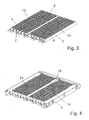
- FIGS. 3 and 4 show part of a heating arrangement 1 according to the invention with the assemblies 13 and 14, which are supplied via the mains voltage, for example 230 V, and thus form the high-voltage assemblies of the heating arrangement 1.
- the structure of the individual assemblies 13 and 14 is substantially identical to that of the illustrated in Figs. 1 and 2 assemblies 11 and 12.
- the PTC elements 2 of the assemblies 13 and 14, adapted to the mains voltage and thus advantageously different from the PTC elements 2 of the low-voltage assemblies 11 and 12 are formed.
- FIG. 4 shows, analogously to FIG. 2, the arrangement of the high-voltage assemblies 13 and 14 in a frame 4 which is essentially the same as the frame 9 for the low-voltage assemblies.
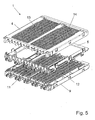
- Fig. 5 shows the heater assembly 1 in the preassembled state in the manner of an exploded view.
- an intermediate frame 5 is arranged between the enclosed in the frame 4 high-voltage assemblies 13 and 14 and enclosed in the frame 9 low-voltage assemblies 11 and 12, an intermediate frame 5 is arranged.
- the intermediate frame 5 is designed so that it connects the two frames 4 and 9 in the illustrated embodiment via a clip connection together to form a compact overall unit as shown in Fig. 6.
- the assemblies 11, 12, 13 and 14 are arranged in the frame 4 and 9 so that they are electrically and / or thermally insulated from each other.
- the intermediate frame 5 may alternatively also have a transverse strut in the plane of symmetry according to the frames 4 and 9.
- the elements for contacting 7 project with their outer ends beyond the frames 9, 4 and the intermediate frame 5. At these ends are corresponding contact rails, which are provided in a side cover 10, shown in Fig. 7, the plastic frame 4 and 9, and allow a common electrical contacting of the individual heating strands 8, each of the low and high voltage assemblies. In order to ensure a secure contact, may be provided on the elements for contacting spring tongues.
- the cover 10 is attached laterally and by means of further clip connections held on the two frame elements. The fully assembled state is shown in FIG.
- the low and high voltage assemblies are arranged in the flow direction of the air to be heated directly behind one another and brought together by means of the frame 9 and 4 and the intermediate frame 5 to a very compact heating arrangement 1.
- the individual heating strands 8 can serve as standard elements, which can be used in different frames 4 and 9, whereby the manufacturing costs are reduced.
- the heating strands 8 of the low-voltage and high-voltage assemblies are identical in the present case.
- Each assembly consists of subassemblies, so that the manufacturing costs can be further reduced.
- the extending in the longitudinal direction of the PTC elements 2 transverse strut 15 and 16 in the frame 9 and 4 serves for a stabilization and on the other hand, the spatial separation of the two modules. Due to the separation of the modules, the independent control option and the cross braces 15 and 16, the heating arrangement is advantageously used for a two-zone air conditioning.
- a transverse strut arranged perpendicular to the PTC elements.
- two zones of the air conditioning are coupled together due to the presence of only two modules for low and high voltage part, ie the driver-side air conditioning of the front and rear and the passenger side air conditioning of the front and rear are coupled together.
- This has, since the heater has essentially only an auxiliary function, no significant impairment of comfort result.
- mirror-image or identical assemblies can be used, wherein the electrical contact is preferably from both sides.
Landscapes
- Engineering & Computer Science (AREA)
- Physics & Mathematics (AREA)
- Thermal Sciences (AREA)
- Mechanical Engineering (AREA)
- Chemical & Material Sciences (AREA)
- Combustion & Propulsion (AREA)
- General Engineering & Computer Science (AREA)
- Air-Conditioning For Vehicles (AREA)
Priority Applications (2)
| Application Number | Priority Date | Filing Date | Title |
|---|---|---|---|
| EP04292053A EP1630488A1 (fr) | 2004-08-13 | 2004-08-13 | Dispositif de chauffage avec éléments de chauffage électriques, en particulier pour un véhicule |
| EP20050291720 EP1626231B1 (fr) | 2004-08-13 | 2005-08-12 | Dispositif de chauffage avec éléments de chauffage électriques, en particulier pour un véhicule |
Applications Claiming Priority (1)
| Application Number | Priority Date | Filing Date | Title |
|---|---|---|---|
| EP04292053A EP1630488A1 (fr) | 2004-08-13 | 2004-08-13 | Dispositif de chauffage avec éléments de chauffage électriques, en particulier pour un véhicule |
Publications (1)
| Publication Number | Publication Date |
|---|---|
| EP1630488A1 true EP1630488A1 (fr) | 2006-03-01 |
Family
ID=34931343
Family Applications (1)
| Application Number | Title | Priority Date | Filing Date |
|---|---|---|---|
| EP04292053A Withdrawn EP1630488A1 (fr) | 2004-08-13 | 2004-08-13 | Dispositif de chauffage avec éléments de chauffage électriques, en particulier pour un véhicule |
Country Status (1)
| Country | Link |
|---|---|
| EP (1) | EP1630488A1 (fr) |
Cited By (2)
| Publication number | Priority date | Publication date | Assignee | Title |
|---|---|---|---|---|
| ITRM20120022A1 (it) * | 2012-01-20 | 2013-07-21 | Bitron Spa | Dispositivo di riscaldamento. |
| FR3057815A1 (fr) * | 2016-10-21 | 2018-04-27 | Valeo Systemes Thermiques | Dispositif de chauffage additionnel electrique |
Citations (6)
| Publication number | Priority date | Publication date | Assignee | Title |
|---|---|---|---|---|
| EP0538131A1 (fr) * | 1991-10-15 | 1993-04-21 | Valeo Climatisation | Installation de chauffage de l'habitacle d'un véhicule automobile, notamment d'un véhicule à propulsion électrique |
| DE9407104U1 (de) * | 1994-04-29 | 1994-10-13 | Sunlead Electrical Corp., Taipeh/T'ai-pei | Heizvorrichtung |
| US6124570A (en) * | 1998-02-20 | 2000-09-26 | Micro Compact Car Ag | Heating and air conditioning system for vehicles |
| DE10025713A1 (de) * | 2000-05-25 | 2001-12-06 | Webasto Thermosysteme Gmbh | Heizsystem |
| DE10050429A1 (de) * | 2000-10-12 | 2002-04-18 | Krah Rwi Elektronische Bauelem | Elektrische Zusatz-Heizeinrichtung, insbesondere für Kraftfahrzeuge |
| EP1432287A1 (fr) * | 2002-12-19 | 2004-06-23 | Catem GmbH & Co.KG | Dispositif de chauffage électrique avec boítier |
-
2004
- 2004-08-13 EP EP04292053A patent/EP1630488A1/fr not_active Withdrawn
Patent Citations (6)
| Publication number | Priority date | Publication date | Assignee | Title |
|---|---|---|---|---|
| EP0538131A1 (fr) * | 1991-10-15 | 1993-04-21 | Valeo Climatisation | Installation de chauffage de l'habitacle d'un véhicule automobile, notamment d'un véhicule à propulsion électrique |
| DE9407104U1 (de) * | 1994-04-29 | 1994-10-13 | Sunlead Electrical Corp., Taipeh/T'ai-pei | Heizvorrichtung |
| US6124570A (en) * | 1998-02-20 | 2000-09-26 | Micro Compact Car Ag | Heating and air conditioning system for vehicles |
| DE10025713A1 (de) * | 2000-05-25 | 2001-12-06 | Webasto Thermosysteme Gmbh | Heizsystem |
| DE10050429A1 (de) * | 2000-10-12 | 2002-04-18 | Krah Rwi Elektronische Bauelem | Elektrische Zusatz-Heizeinrichtung, insbesondere für Kraftfahrzeuge |
| EP1432287A1 (fr) * | 2002-12-19 | 2004-06-23 | Catem GmbH & Co.KG | Dispositif de chauffage électrique avec boítier |
Cited By (2)
| Publication number | Priority date | Publication date | Assignee | Title |
|---|---|---|---|---|
| ITRM20120022A1 (it) * | 2012-01-20 | 2013-07-21 | Bitron Spa | Dispositivo di riscaldamento. |
| FR3057815A1 (fr) * | 2016-10-21 | 2018-04-27 | Valeo Systemes Thermiques | Dispositif de chauffage additionnel electrique |
Similar Documents
| Publication | Publication Date | Title |
|---|---|---|
| EP1626231B1 (fr) | Dispositif de chauffage avec éléments de chauffage électriques, en particulier pour un véhicule | |
| EP1780061B1 (fr) | Dispositif de chauffage électrique pour un véhicule automobile | |
| EP1452357B1 (fr) | Appareil de chauffage électrique avec plusieurs zones de chauffage | |
| EP1318694B1 (fr) | Dispositif de chauffage électrique | |
| DE19925757B4 (de) | Heizeinrichtung, insbesondere für ein Kraftfahrzeug | |
| WO2006012963A1 (fr) | Dispositif de chauffage comportant un element chauffant, destine notamment a un vehicule a moteur | |
| EP1884383B1 (fr) | Dispositif de chauffage électrique, en particulier pour un véhicule | |
| WO2006037534A1 (fr) | Systeme de chauffage electrique, notamment pour un vehicule automobile | |
| DE19957452B4 (de) | Elektrische Heizeinrichtung, insbesondere für ein Kraftfahrzeug | |
| DE19902050C2 (de) | Heizungs- oder Klimaanlage für Fahrzeuge | |
| EP1926346B1 (fr) | Dispositif de chauffage électrique, en particulier de véhicules | |
| EP1523226B1 (fr) | Ensemble de chauffage comprenant des éléments PTC, particulièrement pour véhicules à moteurs | |
| WO2006010436A1 (fr) | Systeme de chauffage a element a coefficient de temperature positif, notamment pour un vehicule automobile | |
| EP1522439B2 (fr) | Dispositif de chauffage avec élément à coefficient positif, en particulier pour un véhicule automobile | |
| EP2145782A2 (fr) | Chauffage de véhicule | |
| WO2005060310A1 (fr) | Dispositif de chauffe electrique pour un vehicule a moteur | |
| EP1691579A1 (fr) | Dispositif de chauffage électrique, en particulier pour véhicule à moteur | |
| EP1630488A1 (fr) | Dispositif de chauffage avec éléments de chauffage électriques, en particulier pour un véhicule | |
| WO2005039242A1 (fr) | Dispositif de chauffage pourvu d'un element ptc, conçu en particulier pour un vehicule automobile | |
| DE102018207037A1 (de) | Elektrische Heizeinrichtung mit einem eine Rippenstruktur aufweisenden Kühlkörper | |
| EP1503153B1 (fr) | Dispositif d'échange de chaleur | |
| EP1486363B1 (fr) | Dispositif de chauffage comprenant un élément ptc, en particulier pour véhicule | |
| DE10301056A1 (de) | Heizvorrichtung mit PTC-Elementen | |
| EP2360437B1 (fr) | dispositif de chauffage electrique | |
| EP1457743B1 (fr) | Réchauffeur électrique, spécialement pour une voiture |
Legal Events
| Date | Code | Title | Description |
|---|---|---|---|
| PUAI | Public reference made under article 153(3) epc to a published international application that has entered the european phase |
Free format text: ORIGINAL CODE: 0009012 |
|
| AK | Designated contracting states |
Kind code of ref document: A1 Designated state(s): AT BE BG CH CY CZ DE DK EE ES FI FR GB GR HU IE IT LI LU MC NL PL PT RO SE SI SK TR |
|
| AX | Request for extension of the european patent |
Extension state: AL HR LT LV MK |
|
| 17P | Request for examination filed |
Effective date: 20060901 |
|
| AKX | Designation fees paid |
Designated state(s): AT BE BG CH CY CZ DE DK EE ES FI FR GB GR HU IE IT LI LU MC NL PL PT RO SE SI SK TR |
|
| AXX | Extension fees paid |
Extension state: MK Payment date: 20060901 Extension state: LV Payment date: 20060901 Extension state: LT Payment date: 20060901 Extension state: HR Payment date: 20060901 Extension state: AL Payment date: 20060901 |
|
| 17Q | First examination report despatched |
Effective date: 20061013 |
|
| STAA | Information on the status of an ep patent application or granted ep patent |
Free format text: STATUS: THE APPLICATION HAS BEEN WITHDRAWN |
|
| 18W | Application withdrawn |
Effective date: 20061120 |