EP1620783B1 - Procede et dispositif de gestion de puissance dynamique dans un systeme de processeur - Google Patents
Procede et dispositif de gestion de puissance dynamique dans un systeme de processeur Download PDFInfo
- Publication number
- EP1620783B1 EP1620783B1 EP04750438.6A EP04750438A EP1620783B1 EP 1620783 B1 EP1620783 B1 EP 1620783B1 EP 04750438 A EP04750438 A EP 04750438A EP 1620783 B1 EP1620783 B1 EP 1620783B1
- Authority
- EP
- European Patent Office
- Prior art keywords
- processor
- samples
- sample
- information
- monitored
- Prior art date
- Legal status (The legal status is an assumption and is not a legal conclusion. Google has not performed a legal analysis and makes no representation as to the accuracy of the status listed.)
- Expired - Lifetime
Links
- 238000000034 method Methods 0.000 title claims description 17
- 229920006395 saturated elastomer Polymers 0.000 claims description 36
- 230000007704 transition Effects 0.000 claims 2
- 238000012545 processing Methods 0.000 description 7
- 230000002093 peripheral effect Effects 0.000 description 6
- 238000010586 diagram Methods 0.000 description 5
- 230000008859 change Effects 0.000 description 3
- 230000000694 effects Effects 0.000 description 2
- 230000006870 function Effects 0.000 description 2
- 238000012986 modification Methods 0.000 description 2
- 230000004048 modification Effects 0.000 description 2
- 230000003287 optical effect Effects 0.000 description 2
- 230000008569 process Effects 0.000 description 2
- 230000000644 propagated effect Effects 0.000 description 2
- 208000012886 Vertigo Diseases 0.000 description 1
- 238000013459 approach Methods 0.000 description 1
- 238000013461 design Methods 0.000 description 1
- 230000007246 mechanism Effects 0.000 description 1
- 238000012544 monitoring process Methods 0.000 description 1
- 230000006855 networking Effects 0.000 description 1
- 230000008447 perception Effects 0.000 description 1
- 230000009467 reduction Effects 0.000 description 1
- 230000004044 response Effects 0.000 description 1
- 238000004088 simulation Methods 0.000 description 1
- 238000012546 transfer Methods 0.000 description 1
- 231100000889 vertigo Toxicity 0.000 description 1
Images


Classifications
-
- G—PHYSICS
- G06—COMPUTING; CALCULATING OR COUNTING
- G06F—ELECTRIC DIGITAL DATA PROCESSING
- G06F1/00—Details not covered by groups G06F3/00 - G06F13/00 and G06F21/00
- G06F1/26—Power supply means, e.g. regulation thereof
-
- G—PHYSICS
- G06—COMPUTING; CALCULATING OR COUNTING
- G06F—ELECTRIC DIGITAL DATA PROCESSING
- G06F1/00—Details not covered by groups G06F3/00 - G06F13/00 and G06F21/00
- G06F1/26—Power supply means, e.g. regulation thereof
- G06F1/32—Means for saving power
- G06F1/3203—Power management, i.e. event-based initiation of a power-saving mode
-
- Y—GENERAL TAGGING OF NEW TECHNOLOGICAL DEVELOPMENTS; GENERAL TAGGING OF CROSS-SECTIONAL TECHNOLOGIES SPANNING OVER SEVERAL SECTIONS OF THE IPC; TECHNICAL SUBJECTS COVERED BY FORMER USPC CROSS-REFERENCE ART COLLECTIONS [XRACs] AND DIGESTS
- Y02—TECHNOLOGIES OR APPLICATIONS FOR MITIGATION OR ADAPTATION AGAINST CLIMATE CHANGE
- Y02D—CLIMATE CHANGE MITIGATION TECHNOLOGIES IN INFORMATION AND COMMUNICATION TECHNOLOGIES [ICT], I.E. INFORMATION AND COMMUNICATION TECHNOLOGIES AIMING AT THE REDUCTION OF THEIR OWN ENERGY USE
- Y02D10/00—Energy efficient computing, e.g. low power processors, power management or thermal management
Definitions
- the field of invention relates generally to processor systems and, more specifically but not exclusively relates to power management for processor systems.
- the computing platform (including the processor) is commonly designed to increase performance.
- computing platforms are also designed to reduce power consumption. Typically, these design goals are in conflict.
- One conventional solution to these goals is to provide a means for a user to switch the configuration of the computing platform between a high performance mode and a power conservation mode, as desired.
- a computing platform may allow a user to select the desired mode via a hardware switch or via a menu and dialog box displayed by the computing platform. Such an approach requires user intervention.
- US 6158012 discloses a real-time power conservation and thermal management apparatus and method for portable computers and employs a monitor to determine whether a CPU may rest based upon a real-time sample of the CPU activity and temperature levels and to activate a hardware-selector to carry out the monitor's determination.
- Flautner K et al: 'Vertigo: Automatic Performance-Setting for Linux' discusses a power management system which makes decisions automatically, without any application-specific involvement.
- a hierarchy of performance-setting algorithms, each specialized for different workload characteristics, can be used for controlling the processor's performance.
- the algorithms operate independently from one another and can be dynamically configured.
- a system includes a processor and a system memory to store an operating system that causes the processor to operate in one of multiple run states that have different performance and/or power dissipation levels.
- the operating system selects the run state in response to processor information being monitored by the operating system.
- the processor information can be the processor load history.
- the operating system predicts future states of the processor information. In one embodiment, the operating system predicts the future processor load based on the monitored processor load history. In a further refinement of this aspect, the operating system can take an average of the prediction and the actual processor information to be used in selecting a processor run state.
- the operating system in monitoring the processor information, tracks the number of consecutive saturated samples that occur during a selected window of samples.
- the operating system makes a prediction of future processor information samples based on the number of consecutive saturated samples.
- the operating system can vary the size of the window, the threshold for defining a saturated sample, the thresholds for transitioning between run states and/or the sample rate of the processor information.
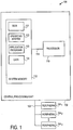
- FIG. 1 illustrates an exemplary computing system 100 having dynamic power management according to one embodiment of the present invention.
- computer system 100 includes a central processing unit 102 and peripherals 104 1 -104 X .
- Central processing unit 102 is connected to peripherals 104 1 -104 X via one or more buses 106.
- central processing unit 102 may include a peripheral controller or "south bridge" (not shown) to communicate with peripherals 104 1 -104 X .
- central processing unit 102 includes a processor 110 and a system memory 112 (typically implemented in RAM and ROM).
- Processor 110 is connected to system memory 112 via one or more buses 114.
- a memory controller (not shown) may be used to transfer information between processor 110 and system memory 112.
- central processing unit 102 can include multiple processors.
- System memory 112 is typically used to store a basic input output system (BIOS) 121, an operating system 122, one or more application programs 123 and data 123.
- BIOS basic input output system
- Processor 110 can be any suitable processor device such as, for example, a general-purpose microprocessor (such as commercially available from several vendors), a microcontroller, a digital signal processor, etc. This list of processor devices is representative and not intended to be exhaustive.
- peripherals 104 1 -104 X can include one or more monitors, memory drives (e.g ., hard disk drives, floppy disk drives, CD-ROM drives, DVD drives, flash memory drives, etc .), printers, scanners, etc. This list of peripherals is representative and not intended to be exhaustive.
- operating system 122 is configured to provide dynamic power management by configuring processor 110 to operate in one of several run states, based on monitored processor information. This dynamic power management is described in more detail below.
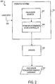
- FIG 2 illustrates a dynamic power management system 200 implemented in central processing unit 102 ( Figure 1 ), according to one embodiment of the present invention.
- dynamic power management system 200 includes operating system 122 ( Figure 1 ) having a processor monitor 201 and a power/performance state controller (also referred to herein as state controller) 203.
- Dynamic power management system 200 also includes one or more software drivers 205 and processor power/performance hardware 207.
- dynamic power management system 200 can "run" in a single processor to manage power/performance using all of the processors.
- the multiple processors can be divided into groups, with a processor of each group managing power/performance using the processors of its group.
- processor monitor 201 is a module that monitors one or more selected parameters while processor 110 ( Figure 1 ) operates.
- processor monitor 201 can monitor the processor's workload. Such monitors are already implemented in most commercially available operating systems.
- State controller 203 in this embodiment, is a module that determines a runs state for processor 110 ( Figure 1 ) based on information monitored by processor monitor 201.
- state controller 203 is implemented as a finite state machine.
- Drivers 205 are modules that provide control signals to processor hardware to change performance and/or power dissipation characteristics of processor 110 ( Figure 1 ). For example, in some embodiments drivers 205 are used to change the clock frequency or "core" voltage of processor 110 ( Figure 1 ) to alter performance/power dissipation characteristics of processor 110 ( Figure 1 ).
- processor power/performance hardware 207 includes a clock generator, a core voltage regulator, or other circuitry that can vary the power/performance characteristics of processor 110 ( Figure 1 ).
- Processor monitor 201 of operating system 122 is coupled to communicate with state controller 203.
- State controller 203 is coupled to communicate with drivers 205, which are in turn coupled to communicate with processor power/performance hardware 207.
- operating system 122 has means to allow a user to provide input to dynamic power management system 200, as indicated by dashed arrow 209.
- operating system 122 may cause a menu and/or dialog box to be displayed that allows a user to provide the input.
- some embodiments of dynamic power management system 200 have various user configurable parameters (e.g ., thresholds, history sizes, etc .).
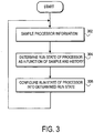
- FIG 3 illustrates an operational flow of dynamic power management system 200 ( Figure 2 ), according to one embodiment of the present invention.
- dynamic power management system 200 operates as follows.
- processor monitor 201 monitors one or more parameters of the operation of processor 110 ( Figure 1 ). In one particular embodiment, processor monitor 201 monitors the workload of processor 110 ( Figure 1 ), although different parameters can be monitored in examples useful to understand the invention. For example, scheduler information (e.g., number of run-able threads) or per-thread statistics (e.g., priority, real-time requirements, % utilization of scheduling quanta) can be monitored. In a further refinement, the rate at which processor monitor 201 samples the processor information can be user configurable. In one embodiment, the most recent N samples of processor information are stored in a sample history. In some embodiments, N can be user configurable.
- the run state of processor 110 is determined as a function of the sample history.
- state controller 203 selects one of two or more possible run states in which processor 110 ( Figure 1 ) can operate.
- the multiple run states have combinations of different processor clock frequencies and/or core voltages.
- the processor's performance and power dissipation characteristics can be changed by changing the processor's run state.
- state controller 203 predicts future processor information samples and then takes an average of the sample history and predicted samples. State controller 203 uses this average to determine what run state to select. For example, the range of averages may be divided into sub-ranges that correspond to particular run states, with state controller 203 determining which sub-range the average falls into. State controller 203 would then cause processor 110 ( Figure 1 ) to operate in the run state corresponding to that sub-range.
- One embodiment of block 304 is described in more detail below in conjunction with Figure 4 .
- the processor is configured to operate in the run state determined in block 304.
- state controller 203 causes one or more of drivers 205 to control (if necessary) processor power/performance hardware 207 to change the processor clock frequency and/or core voltage to the levels corresponding to the determined run state.
- FIG 4 illustrates an operational flow of block 304 ( Figure 3 ), according to one embodiment of the present invention. Referring to Figures 2 and 4 , this embodiment of block 304 is performed as follows.
- a sample of processor information is inserted in the sample history (not shown).
- this sample history is a data structure stored in system memory 112 ( Figure 1 ) to store the N most recent samples.
- Process monitor 201 inserts the most recent sample in the sample history. If the sample history is already full, the oldest sample is discarded and the most recent sample is stored in the opened place.
- future sample(s) are predicted based on the sample history.
- state controller 203 determines a prediction of future samples.
- the prediction is based on the number of the most recent samples that are consecutively greater than a selected threshold (also referred to herein as "saturated samples").
- saturated samples also referred to herein as "saturated samples”
- the number of the most recent consecutive saturated samples is then multiplied by a preselected factor.
- This product e.g., rounded to non-negative integer P
- different algorithms can be used to predict future samples (and need not be saturated samples).
- an average is determined using the sample history and the predicted samples from block 404.
- state controller 203 determines the mean of the N (can be less than N if the sample history is not full) samples stored in the sample history summed with the P predicted saturated samples.
- the P saturated samples (if P is greater than zero) are assumed to have the maximum value that a sample of the processor information can have. For example, if the processor information is workload, then in one embodiment the P saturated samples would each have a value of 100% ( i.e., the processor is working at 100% capacity).
- the value of each saturated sample can be some other preselected value and the average can be calculated in other ways. In this sense, the average can be a value calculated using the sample history and predicted samples, which can be mapped into one of the possible run states of processor 110 ( Figure 1 ).
- the run state is determined as a function of the average determined in block 406.
- state controller 203 selects a run state from the processor's multiple possible run states. For example, the range of averages may be divided into non-overlapping but adjacent sub-ranges, each sub-range corresponding to a unique run state of the possible run states. In this embodiment, state controller 203 determines which sub-range contains the average, which in effect determines the run state. In other embodiments, the ranges may overlap so that hysteresis can be introduced in transitioning between run states .
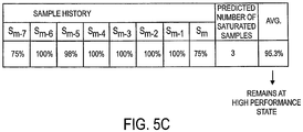
- Figures 5A-5C illustrate examples of how dynamic power management system 200 ( Figure 2 ) process different series of samples, according to one embodiment of the present invention.
- the processor information is the processor workload and the samples are workload percentages.
- the number of predicted saturated samples is equal to the number of most recent accumulated saturated samples (i.e., the multiplying factor is 1) when the most recent sample is saturated. However, if the most recent sample is not saturated, the number of predicted saturated samples is equal to half the number of most recent accumulated saturated samples.
- the threshold for determining whether a sample is saturated is 95% (i.e., samples over 95% are considered saturated).
- the number of run states in this embodiment is two (one being the high performance state and the other being the power saving state).
- the threshold between the two states is also 95% (i.e., an average greater than 95% corresponds to the high performance state) in this embodiment.
- the value of each predicted saturated sample is set to 100%. Still further, the average is calculated as the mean of the entire sample history and predicted samples.
- the most recent sample i.e., sample S n
- sample S n 100%. Consequently, sample S n is saturated.
- the number of predicted saturated samples is the same as the number of the most recent consecutive saturated samples. In this case, the four most recent samples were saturated; thus, P is equal to four.
- the mean of the eight samples of the sample history i.e., samples S n-7 , S n-6 , ..., S n ) and the four predicted saturated samples is 95.6%. Therefore, dynamic power management system 200 ( Figure 2 ) causes processor 110 ( Figure 1 ) to enter the high performance run state.
- the next sample i.e., sample S n+1
- sample S n+1 is 80%.
- sample S n+1 is not saturated.
- the prediction algorithm requires that the number of predicted saturated samples be halved.
- P is reduced to two.
- the mean of the eight samples of the sample history i.e., samples S n-6 , S n-5 , ..., S n , S n+1
- the two predicted saturated samples is 92.9%.
- dynamic power management system 200 ( Figure 2 ) causes processor 110 ( Figure 1 ) to enter the power saving run state.
- This exemplary embodiment shows how dynamic power management system 200 ( Figure 2 ) can quickly respond to load changes.
- the processor can be operated in a low performance/power saving run state so that the computing platform will dissipate less power without causing the user to perceive the lower processor performance.
- This perception is possible because with a relatively low workload, the work is still performed relatively quickly at the lower performance run state. In this way, power dissipation is reduced without perceptibly affecting the user's experience.
- the algorithm is designed with a goal to maximize the amount of time that the processor spends in the power saving run state without causing the user to perceive a reduction in processor performance. In other embodiments, can be used to achieve different power/performance goals.
- Figure 5C illustrates another sequence of eight samples stored in the sample history (i.e., samples S m-7 , S m-6 , ..., S m , with S m being the most recent).
- samples S m-7 , S m-6 , ..., S m were stored in the sample history, followed by the most recent sample that was not saturated (i.e., sample S m at 75%).
- sample S m was received, P is three in this example.
- the average of the sample history and three predicted saturated samples is about 95.3%.
- dynamic power management system 200 causes processor 110 ( Figure 1 ) to remain in the high performance run state. This example illustrates how a single non-saturated sample will not necessarily cause the processor to enter the low power run state after receiving several consecutive saturated samples.
- Embodiments of this invention may be used as or to support a software program executed upon some form of processing core (such as the CPU of a computer) or otherwise implemented or realized upon or within a machine-readable medium.
- a machine-readable medium includes any mechanism for storing or transmitting information in a form readable by a machine ( e.g ., a computer).
- a machine-readable medium can include such as a read only memory (ROM); a random access memory (RAM); a magnetic disk storage media; an optical storage media; and a flash memory device, etc.
- a machine-readable medium can include propagated signals such as electrical, optical, acoustical or other form of propagated signals (e.g., carrier waves, infrared signals, digital signals, etc .).
Claims (18)
- Un système informatique avec
un processeur (110) ; et
une mémoire système (112) couplée au processeur, la mémoire système stockant un système d'exploitation, le système d'exploitation étant configuré pour faire en sorte que le processeur opère dans un état sélectionné parmi une pluralité d'états en fonction du nombre d'un ou plusieurs échantillons futurs prédits d'information de processeur, d'une valeur présélectionnée pour lesdits échantillons futurs prédits et sur des valeurs surveillées d'une pluralité d'échantillons d'information de processeur dans un historique des échantillons, l'information de processeur comprenant une information de charge de processeur et chaque état de la pluralité d'états présentant un niveau de performance différent, et le système d'exploitation étant configuré pour prédire le nombre d'échantillons futurs prédits d'information de processeur en fonction d'un nombre d'échantillons consécutifs de l'historique des échantillons, les échantillons consécutifs ayant des valeurs de charge de processeur surveillées supérieures à un seuil sélectionné. - Le système de la revendication 1, dans lequel une cadence à laquelle l'information de processeur est échantillonnée est ajustable.
- Le système de la revendication 1, dans lequel chaque état présente une combinaison différente de fréquence d'horloge de processeur et de tension de processeur.
- Le système de la revendication 1, dans lequel une valeur de seuil définissant une transition entre états est ajustable.
- Le système de la revendication 1, dans lequel la sélection de l'état parmi la pluralité d'états est fonction d'une moyenne des valeurs surveillées de la pluralité d'échantillons d'information de processeur de l'historique des échantillons et des valeurs des un ou plusieurs échantillons futurs prédits d'information de processeur.
- Le système de la revendication 1, dans lequel le seuil sélectionné définit un échantillon saturé et est ajustable.
- Le système de la revendication 1, dans lequel lorsqu'un échantillon le plus récent d'information de processeur de l'historique des échantillons possède une valeur de charge de processeur surveillée qui est supérieure au seuil sélectionné, le nombre d'échantillons futurs prédits d'information de processeur est égal au nombre d'échantillons consécutifs ayant une valeur de charge de processeur surveillée qui est supérieure au seuil sélectionné et incluant l'échantillon le plus récent.
- Le système de la revendication 1, dans lequel lorsqu'un échantillon le plus récent d'information de processeur de l'historique des échantillons présente une valeur de charge de processeur surveillée qui est inférieure au seuil sélectionné, le nombre d'échantillons futurs prédits d'information de processeur est la moitié du nombre d'échantillons consécutifs, les échantillons consécutifs présentant une valeur de charge de processeur surveillée qui est supérieure au seuil sélectionné et étant reçus séquentiellement antérieurement à l'échantillon le plus récent.
- Un procédé mis en oeuvre par un système d'exploitation d'une plateforme informatique, le procédé comprenant :la réception d'échantillons d'information relative à un fonctionnement d'un processeur (302), faisant en sorte que le processeur (110) opère dans un état sélectionné parmi une pluralité d'états en fonction du nombre d'un ou plusieurs échantillons futurs prédits d'information de processeur (408), d'une valeur présélectionnée pour lesdits échantillons futurs prédits, et des valeurs surveillées d'une pluralité d'échantillons d'information de processeur dans un historique des échantillons, l'information de processeur comprenant une information de charge de processeur et chaque état de la pluralité d'états présentant un niveau de performance différent ; etla prédiction du nombre d'échantillons futurs prédits d'information de processeur en fonction d'un nombre d'échantillons consécutifs d'information de processeur (404) de l'historique des échantillons, les échantillons consécutifs ayant des valeurs de charge de processeur surveillées supérieures à un seuil sélectionné.
- Le procédé de la revendication 9, dans lequel une cadence à laquelle l'information de processeur est échantillonnée est ajustable.
- Le procédé de la revendication 9, dans lequel chaque état présente une combinaison différente de fréquence d'horloge de processeur et de tension de processeur.
- Le procédé de la revendication 9, dans lequel une valeur de seuil définissant une transition entre états est ajustable.
- Le procédé de la revendication 9, comprenant en outre la détermination d'une moyenne des valeurs surveillées des échantillons d'information de processeur de l'historique des échantillons et des valeurs des un ou plusieurs échantillons futurs prédits d'information de processeur.
- Le procédé de la revendication 9, dans lequel le seuil sélectionné définit un échantillon saturé et est ajustable.
- Le procédé de la revendication 9, dans lequel lorsqu'un échantillon le plus récent d'information de processeur de l'historique des échantillons possède une valeur de charge de processeur surveillée qui est supérieure au seuil sélectionné, le nombre d'échantillons futurs prédits d'information de processeur est égal au nombre d'échantillons consécutifs ayant une valeur de charge de processeur surveillée qui est supérieure au seuil sélectionné et incluant l'échantillon le plus récent.
- Le procédé de la revendication 9, dans lequel lorsqu'un échantillon le plus récent d'information de processeur de l'historique des échantillons présente une valeur de charge de processeur surveillée qui est inférieure au seuil sélectionné, le nombre d'échantillons futurs prédits d'information de processeur est la moitié du nombre d'échantillons consécutifs, les échantillons consécutifs présentant une valeur de charge de processeur surveillée qui est supérieure au seuil sélectionné et étant reçus séquentiellement antérieurement à l'échantillon le plus récent.
- Un système d'exploitation (100) destiné à être utilisé par un système informatique, le système d'exploitation possédant un ou plusieurs modules logiciels qui, lorsqu'ils sont exécutés par un processeur (110), mettent en oeuvre le procédé de l'une des revendications 9 à 16.
- Un support lisible par machine (112) avec des instructions qui, lorsqu'elles sont exécutées, font en sorte qu'un système d'exploitation d'une plateforme informatique met en oeuvre le procédé de l'une des revendications 9 à 16.
Applications Claiming Priority (2)
| Application Number | Priority Date | Filing Date | Title |
|---|---|---|---|
| US10/434,515 US7240223B2 (en) | 2003-05-07 | 2003-05-07 | Method and apparatus for dynamic power management in a processor system |
| PCT/US2004/012340 WO2004102363A2 (fr) | 2003-05-07 | 2004-04-21 | Procede et dispositif de gestion de puissance dynamique dans un systeme de processeur |
Publications (2)
| Publication Number | Publication Date |
|---|---|
| EP1620783A2 EP1620783A2 (fr) | 2006-02-01 |
| EP1620783B1 true EP1620783B1 (fr) | 2018-09-12 |
Family
ID=33416706
Family Applications (1)
| Application Number | Title | Priority Date | Filing Date |
|---|---|---|---|
| EP04750438.6A Expired - Lifetime EP1620783B1 (fr) | 2003-05-07 | 2004-04-21 | Procede et dispositif de gestion de puissance dynamique dans un systeme de processeur |
Country Status (8)
| Country | Link |
|---|---|
| US (2) | US7240223B2 (fr) |
| EP (1) | EP1620783B1 (fr) |
| JP (2) | JP4065458B2 (fr) |
| KR (1) | KR100858766B1 (fr) |
| CN (1) | CN1784646B (fr) |
| AU (1) | AU2004239644B2 (fr) |
| CA (1) | CA2515855C (fr) |
| WO (1) | WO2004102363A2 (fr) |
Families Citing this family (69)
| Publication number | Priority date | Publication date | Assignee | Title |
|---|---|---|---|---|
| JP2007502477A (ja) * | 2003-05-27 | 2007-02-08 | コーニンクレッカ フィリップス エレクトロニクス エヌ ヴィ | 電力消費のモニタおよび制御 |
| US7392099B2 (en) * | 2003-12-12 | 2008-06-24 | Hewlett-Packard Development Company, L.P. | System and method for power management when an operating voltage is between two thresholds |
| US7337335B2 (en) * | 2004-12-21 | 2008-02-26 | Packet Digital | Method and apparatus for on-demand power management |
| US7228446B2 (en) * | 2004-12-21 | 2007-06-05 | Packet Digital | Method and apparatus for on-demand power management |
| US8332226B1 (en) | 2005-01-07 | 2012-12-11 | At&T Intellectual Property Ii, L.P. | System and method of dynamically modifying a spoken dialog system to reduce hardware requirements |
| US9608929B2 (en) * | 2005-03-22 | 2017-03-28 | Live Nation Entertainment, Inc. | System and method for dynamic queue management using queue protocols |
| US7594132B2 (en) * | 2005-05-18 | 2009-09-22 | Lg Electronics Inc. | Computer system with power-saving capability and method for implementing power-saving mode in computer system |
| US7523269B2 (en) * | 2005-07-22 | 2009-04-21 | Microsoft Corporation | Preparing memory to allow access to data when primary operating system is unavailable |
| CN100346268C (zh) * | 2005-08-18 | 2007-10-31 | 复旦大学 | 信息安全SoC中基于门控时钟的动态功耗管理方法 |
| US7647516B2 (en) * | 2005-09-22 | 2010-01-12 | Hewlett-Packard Development Company, L.P. | Power consumption management among compute nodes |
| US7581125B2 (en) * | 2005-09-22 | 2009-08-25 | Hewlett-Packard Development Company, L.P. | Agent for managing power among electronic systems |
| US8006113B2 (en) * | 2005-10-27 | 2011-08-23 | Freescale Semiconductor, Inc. | System and method for controlling voltage level and clock frequency supplied to a system |
| US7516342B2 (en) * | 2005-12-30 | 2009-04-07 | Intel Corporation | Method, apparatus and system to dynamically choose an optimum power state |
| US7930564B2 (en) * | 2006-07-31 | 2011-04-19 | Intel Corporation | System and method for controlling processor low power states |
| CN100428116C (zh) * | 2006-09-08 | 2008-10-22 | 华南理工大学 | 一种基于嵌入式系统的动态电源管理方法 |
| US7681054B2 (en) * | 2006-10-03 | 2010-03-16 | International Business Machines Corporation | Processing performance improvement using activity factor headroom |
| US7689851B2 (en) * | 2006-10-27 | 2010-03-30 | Hewlett-Packard Development Company, L.P. | Limiting power state changes to a processor of a computer device |
| US7818596B2 (en) * | 2006-12-14 | 2010-10-19 | Intel Corporation | Method and apparatus of power management of processor |
| CN101558383B (zh) * | 2006-12-14 | 2012-11-14 | 英特尔公司 | 处理器的电源管理方法和装置 |
| US7430675B2 (en) * | 2007-02-16 | 2008-09-30 | Apple Inc. | Anticipatory power management for battery-powered electronic device |
| US7925901B2 (en) * | 2007-03-15 | 2011-04-12 | International Business Machines Corporation | Method and system for estimating processor utilization from power measurements |
| US7725296B1 (en) * | 2007-09-24 | 2010-05-25 | United Services Automobile Association (Usaa) | Estimating processor usage |
| US7904287B2 (en) * | 2007-11-13 | 2011-03-08 | International Business Machines Corporation | Method and system for real-time prediction of power usage for a change to another performance state |
| US7441135B1 (en) | 2008-01-14 | 2008-10-21 | International Business Machines Corporation | Adaptive dynamic buffering system for power management in server clusters |
| US7992015B2 (en) * | 2008-02-05 | 2011-08-02 | Dell Products L.P. | Processor performance state optimization |
| EP2260363A1 (fr) * | 2008-02-25 | 2010-12-15 | ST-Ericsson SA | Dispositif de traitement de données à niveau de performance ajustable et procédé de fonctionnement d'un tel dispositif |
| US8312299B2 (en) * | 2008-03-28 | 2012-11-13 | Packet Digital | Method and apparatus for dynamic power management control using serial bus management protocols |
| US8102552B2 (en) | 2008-04-03 | 2012-01-24 | Sharp Laboratories Of America, Inc. | Performance monitoring and control of a multifunction printer |
| US8392924B2 (en) | 2008-04-03 | 2013-03-05 | Sharp Laboratories Of America, Inc. | Custom scheduling and control of a multifunction printer |
| US8028182B2 (en) * | 2008-06-04 | 2011-09-27 | Dell Products L.P. | Dynamic CPU voltage regulator phase shedding |
| US8078901B1 (en) | 2008-06-16 | 2011-12-13 | Western Digital Technologies, Inc. | Method for increasing a processor operating frequency when other subsystem demands are low |
| US8212944B2 (en) * | 2008-07-10 | 2012-07-03 | Qualcomm Incorporated | Fast stream switching |
| US8094643B2 (en) * | 2008-07-10 | 2012-01-10 | Qualcomm Incorporated | Dynamic power management for time division multiplexing devices |
| US8244296B2 (en) * | 2008-10-15 | 2012-08-14 | Apple Inc. | Dynamic thermal control for wireless transceivers |
| US8170606B2 (en) * | 2008-10-15 | 2012-05-01 | Apple Inc. | Dynamic thermal control for wireless transceivers |
| US8707060B2 (en) * | 2008-10-31 | 2014-04-22 | Intel Corporation | Deterministic management of dynamic thermal response of processors |
| US20100148708A1 (en) * | 2008-12-11 | 2010-06-17 | Jorgenson Joel A | Voltage scaling of an electric motor load to reduce power consumption |
| US9082419B1 (en) | 2009-06-08 | 2015-07-14 | Western Digitial Technologies, Inc. | Disk drive configuring power mode of disk drive relative to servo gate |
| US20110018346A1 (en) * | 2009-07-27 | 2011-01-27 | Dixon Ryan G | Location-Based Power Profiles |
| KR101617377B1 (ko) * | 2009-11-06 | 2016-05-02 | 삼성전자주식회사 | 동적 전압 주파수 스케일링 방법 |
| US9098274B2 (en) * | 2009-12-03 | 2015-08-04 | Intel Corporation | Methods and apparatuses to improve turbo performance for events handling |
| US9104411B2 (en) | 2009-12-16 | 2015-08-11 | Qualcomm Incorporated | System and method for controlling central processing unit power with guaranteed transient deadlines |
| US8909962B2 (en) | 2009-12-16 | 2014-12-09 | Qualcomm Incorporated | System and method for controlling central processing unit power with guaranteed transient deadlines |
| US9128705B2 (en) | 2009-12-16 | 2015-09-08 | Qualcomm Incorporated | System and method for controlling central processing unit power with reduced frequency oscillations |
| US9176572B2 (en) | 2009-12-16 | 2015-11-03 | Qualcomm Incorporated | System and method for controlling central processing unit power with guaranteed transient deadlines |
| US9563250B2 (en) * | 2009-12-16 | 2017-02-07 | Qualcomm Incorporated | System and method for controlling central processing unit power based on inferred workload parallelism |
| US8775830B2 (en) * | 2009-12-16 | 2014-07-08 | Qualcomm Incorporated | System and method for dynamically controlling a plurality of cores in a multicore central processing unit based on temperature |
| US20110145559A1 (en) * | 2009-12-16 | 2011-06-16 | Thomson Steven S | System and method for controlling central processing unit power with guaranteed steady state deadlines |
| US8650426B2 (en) | 2009-12-16 | 2014-02-11 | Qualcomm Incorporated | System and method for controlling central processing unit power in a virtualized system |
| US8689037B2 (en) * | 2009-12-16 | 2014-04-01 | Qualcomm Incorporated | System and method for asynchronously and independently controlling core clocks in a multicore central processing unit |
| US8352759B2 (en) * | 2010-01-11 | 2013-01-08 | Qualcomm Incorporated | System and method of monitoring a central processing unit in real time |
| US8667308B2 (en) | 2010-06-18 | 2014-03-04 | Apple Inc. | Dynamic voltage dithering |
| US8527801B2 (en) | 2010-06-30 | 2013-09-03 | International Business Machines Corporation | Performance control of frequency-adapting processors by voltage domain adjustment |
| US8516284B2 (en) | 2010-11-04 | 2013-08-20 | International Business Machines Corporation | Saving power by placing inactive computing devices in optimized configuration corresponding to a specific constraint |
| US8521942B2 (en) | 2011-03-21 | 2013-08-27 | Microsoft Corporation | HID over simple peripheral buses |
| TWI461897B (zh) * | 2011-11-16 | 2014-11-21 | Wistron Corp | 電源控制裝置及電子裝置 |
| US8725916B2 (en) * | 2012-01-07 | 2014-05-13 | Microsoft Corporation | Host side implementation for HID I2C data bus |
| CN102622078B (zh) * | 2012-01-20 | 2014-10-15 | 李涛 | 基于可再生能源的计算机的性能功耗比优化方法和装置 |
| US8994346B2 (en) | 2012-02-09 | 2015-03-31 | Dell Products Lp | Systems and methods for dynamic management of switching frequency for voltage regulation |
| US9442732B2 (en) * | 2012-03-19 | 2016-09-13 | Via Technologies, Inc. | Running state power saving via reduced instructions per clock operation |
| US9201477B2 (en) | 2012-05-29 | 2015-12-01 | Apple Inc. | Power management with thermal credits |
| CN102915108B (zh) * | 2012-09-30 | 2014-04-16 | 安科智慧城市技术(中国)有限公司 | 一种嵌入式处理器内核电压动态调整装置和方法 |
| US8984308B2 (en) * | 2012-12-03 | 2015-03-17 | Qualcomm Incorporated | System and method of adaptive voltage scaling |
| CN103049803B (zh) * | 2013-01-10 | 2016-12-28 | 华北电力大学 | 基于高斯液面法的负荷预测算法的参数寻优方法 |
| US9195293B1 (en) | 2013-05-03 | 2015-11-24 | Western Digital Technologies, Inc. | User controlled data storage device power and performance settings |
| WO2015019476A1 (fr) * | 2013-08-08 | 2015-02-12 | 富士通株式会社 | Dispositif de sélection sélectionnant des informations d'état d'une valeur de consommation d'énergie étant inférieure ou égale à une valeur de puissance prescrite, sur la base d'une valeur de performance de traitement mesurée |
| US9436265B2 (en) | 2013-10-24 | 2016-09-06 | Fujitsu Limited | Information processing apparatus and load control method |
| CN103744502B (zh) * | 2013-12-31 | 2016-01-27 | 东软集团股份有限公司 | 确定嵌入式系统的临界频率的方法及装置 |
| US20240004443A1 (en) * | 2022-06-29 | 2024-01-04 | International Business Machines Corporation | Thermal and performance management |
Family Cites Families (19)
| Publication number | Priority date | Publication date | Assignee | Title |
|---|---|---|---|---|
| US5218704A (en) * | 1989-10-30 | 1993-06-08 | Texas Instruments | Real-time power conservation for portable computers |
| US6158012A (en) | 1989-10-30 | 2000-12-05 | Texas Instruments Incorporated | Real-time power conservation and thermal management for computers |
| US5396635A (en) * | 1990-06-01 | 1995-03-07 | Vadem Corporation | Power conservation apparatus having multiple power reduction levels dependent upon the activity of the computer system |
| US5287292A (en) * | 1992-10-16 | 1994-02-15 | Picopower Technology, Inc. | Heat regulator for integrated circuits |
| US5339445A (en) * | 1992-11-16 | 1994-08-16 | Harris Corporation | Method of autonomously reducing power consumption in a computer sytem by compiling a history of power consumption |
| US5422806A (en) * | 1994-03-15 | 1995-06-06 | Acc Microelectronics Corporation | Temperature control for a variable frequency CPU |
| US5481733A (en) * | 1994-06-15 | 1996-01-02 | Panasonic Technologies, Inc. | Method for managing the power distributed to a disk drive in a laptop computer |
| US5812860A (en) * | 1996-02-12 | 1998-09-22 | Intel Corporation | Method and apparatus providing multiple voltages and frequencies selectable based on real time criteria to control power consumption |
| US6785826B1 (en) * | 1996-07-17 | 2004-08-31 | International Business Machines Corporation | Self power audit and control circuitry for microprocessor functional units |
| JPH11161383A (ja) * | 1997-09-05 | 1999-06-18 | Texas Instr Inc <Ti> | オンチップ・アクティビティに応答してマイクロプロセッサの電力消費を調節するためのマイクロプロセッサ回路、システム、及び方法 |
| US5954820A (en) * | 1997-09-26 | 1999-09-21 | International Business Machines Corporation | Portable computer with adaptive demand-driven power management |
| US6446214B2 (en) | 1998-06-08 | 2002-09-03 | Microsoft Corporation | System and method for handling power state change requests initiated by peripheral devices |
| US6442699B1 (en) * | 1998-09-18 | 2002-08-27 | Matsushita Electric Industrial Co., Ltd. | Power control method and apparatus therefor |
| US6442700B1 (en) | 1999-08-10 | 2002-08-27 | Intel Corporation | Thermal control within systems having multiple CPU performance states |
| US6198245B1 (en) * | 1999-09-20 | 2001-03-06 | O2 Micro International Ltd. | Look-ahead closed-loop thermal management |
| US6795927B1 (en) * | 2001-05-01 | 2004-09-21 | Advanced Micro Devices, Inc. | Power state resynchronization |
| US6845456B1 (en) * | 2001-05-01 | 2005-01-18 | Advanced Micro Devices, Inc. | CPU utilization measurement techniques for use in power management |
| JP4143283B2 (ja) * | 2001-09-12 | 2008-09-03 | 株式会社日立製作所 | 計算機の処理性能変更装置 |
| US6996441B1 (en) * | 2002-03-11 | 2006-02-07 | Advanced Micro Devices, Inc. | Forward-looking fan control using system operation information |
-
2003
- 2003-05-07 US US10/434,515 patent/US7240223B2/en active Active
-
2004
- 2004-04-21 JP JP2006501289A patent/JP4065458B2/ja not_active Expired - Lifetime
- 2004-04-21 KR KR1020057018487A patent/KR100858766B1/ko active IP Right Grant
- 2004-04-21 EP EP04750438.6A patent/EP1620783B1/fr not_active Expired - Lifetime
- 2004-04-21 WO PCT/US2004/012340 patent/WO2004102363A2/fr active Application Filing
- 2004-04-21 CN CN200480011860XA patent/CN1784646B/zh not_active Expired - Lifetime
- 2004-04-21 CA CA002515855A patent/CA2515855C/fr not_active Expired - Fee Related
- 2004-04-21 AU AU2004239644A patent/AU2004239644B2/en not_active Expired
-
2006
- 2006-07-31 US US11/497,467 patent/US7302595B2/en not_active Expired - Lifetime
-
2007
- 2007-07-31 JP JP2007199925A patent/JP4847408B2/ja not_active Expired - Lifetime
Non-Patent Citations (1)
| Title |
|---|
| None * |
Also Published As
| Publication number | Publication date |
|---|---|
| WO2004102363A2 (fr) | 2004-11-25 |
| EP1620783A2 (fr) | 2006-02-01 |
| US20060265616A1 (en) | 2006-11-23 |
| US7302595B2 (en) | 2007-11-27 |
| CA2515855A1 (fr) | 2004-11-25 |
| AU2004239644B2 (en) | 2007-11-01 |
| KR100858766B1 (ko) | 2008-09-16 |
| CN1784646A (zh) | 2006-06-07 |
| AU2004239644A1 (en) | 2004-11-25 |
| KR20050115325A (ko) | 2005-12-07 |
| US20040225902A1 (en) | 2004-11-11 |
| JP2008010000A (ja) | 2008-01-17 |
| JP4065458B2 (ja) | 2008-03-26 |
| US7240223B2 (en) | 2007-07-03 |
| JP2006524374A (ja) | 2006-10-26 |
| JP4847408B2 (ja) | 2011-12-28 |
| WO2004102363A3 (fr) | 2005-02-10 |
| CN1784646B (zh) | 2010-06-16 |
| CA2515855C (fr) | 2009-12-15 |
Similar Documents
| Publication | Publication Date | Title |
|---|---|---|
| EP1620783B1 (fr) | Procede et dispositif de gestion de puissance dynamique dans un systeme de processeur | |
| US7143203B1 (en) | Storage device control responsive to operational characteristics of a system | |
| Irani et al. | Online strategies for dynamic power management in systems with multiple power-saving states | |
| US6289399B1 (en) | Computer and parameter setting method | |
| Liu et al. | Sleepscale: Runtime joint speed scaling and sleep states management for power efficient data centers | |
| US7082373B2 (en) | Dynamic power control apparatus, systems and methods | |
| US8135966B2 (en) | Method and device for power management | |
| EP2250542B1 (fr) | Mise au repos forcée d'un système de traitement de données | |
| US20100332876A1 (en) | Reducing power consumption of computing devices by forecasting computing performance needs | |
| US20160077760A1 (en) | Dynamic memory allocation and relocation to create low power regions | |
| JP3742364B2 (ja) | クロック周波数の制御方法および電子機器 | |
| KR20060081346A (ko) | 복수개의 정보처리시스템의 전력관리 시스템 및 방법 | |
| US20100057404A1 (en) | Optimal Performance and Power Management With Two Dependent Actuators | |
| US20090144572A1 (en) | Apparatus and method for controlling voltage and frequency | |
| JPH11328031A (ja) | 動的変換システムにおけるトレ―スのランク付け方法 | |
| CN102004674A (zh) | 用于基于策略的适应性程序配置的系统及方法 | |
| AU2008200446B2 (en) | Method and apparatus for dynamic power management in a processor system | |
| HoseinyFarahabady et al. | Energy efficient resource controller for Apache Storm | |
| Cappiello et al. | ADSC: application-driven storage control for energy efficiency | |
| JP4535784B2 (ja) | プロセス配置装置、プロセス配置方法及びプロセス配置プログラム | |
| US11747882B2 (en) | Central processor/accelerator power management system | |
| CN116842994B (zh) | 多神经网络执行效率动态优化方法及系统 | |
| Manzak et al. | Low Power Design for DVFS Capable Software | |
| CN116266139A (zh) | 在混合模式下优化dc持久性内存模块(dcpmm)上的内存与存储容量划分 |
Legal Events
| Date | Code | Title | Description |
|---|---|---|---|
| PUAI | Public reference made under article 153(3) epc to a published international application that has entered the european phase |
Free format text: ORIGINAL CODE: 0009012 |
|
| 17P | Request for examination filed |
Effective date: 20050812 |
|
| AK | Designated contracting states |
Kind code of ref document: A2 Designated state(s): AT BE BG CH CY CZ DE DK EE ES FI FR GB GR HU IE IT LI LU MC NL PL PT RO SE SI SK TR |
|
| AX | Request for extension of the european patent |
Extension state: AL HR LT LV MK |
|
| REG | Reference to a national code |
Ref country code: HK Ref legal event code: DE Ref document number: 1080966 Country of ref document: HK |
|
| RIN1 | Information on inventor provided before grant (corrected) |
Inventor name: COX, KEITH Inventor name: DE CESARE, JOSH Inventor name: CULBERT, MICHAEL |
|
| RAP1 | Party data changed (applicant data changed or rights of an application transferred) |
Owner name: APPLE INC. |
|
| 17Q | First examination report despatched |
Effective date: 20100208 |
|
| REG | Reference to a national code |
Ref country code: HK Ref legal event code: WD Ref document number: 1080966 Country of ref document: HK |
|
| GRAP | Despatch of communication of intention to grant a patent |
Free format text: ORIGINAL CODE: EPIDOSNIGR1 |
|
| STAA | Information on the status of an ep patent application or granted ep patent |
Free format text: STATUS: GRANT OF PATENT IS INTENDED |
|
| INTG | Intention to grant announced |
Effective date: 20180403 |
|
| RAP1 | Party data changed (applicant data changed or rights of an application transferred) |
Owner name: APPLE INC. |
|
| GRAS | Grant fee paid |
Free format text: ORIGINAL CODE: EPIDOSNIGR3 |
|
| GRAA | (expected) grant |
Free format text: ORIGINAL CODE: 0009210 |
|
| STAA | Information on the status of an ep patent application or granted ep patent |
Free format text: STATUS: THE PATENT HAS BEEN GRANTED |
|
| AK | Designated contracting states |
Kind code of ref document: B1 Designated state(s): AT BE BG CH CY CZ DE DK EE ES FI FR GB GR HU IE IT LI LU MC NL PL PT RO SE SI SK TR |
|
| AX | Request for extension of the european patent |
Extension state: AL HR LT LV MK |
|
| REG | Reference to a national code |
Ref country code: GB Ref legal event code: FG4D |
|
| REG | Reference to a national code |
Ref country code: CH Ref legal event code: EP |
|
| REG | Reference to a national code |
Ref country code: IE Ref legal event code: FG4D |
|
| REG | Reference to a national code |
Ref country code: DE Ref legal event code: R096 Ref document number: 602004053175 Country of ref document: DE |
|
| REG | Reference to a national code |
Ref country code: AT Ref legal event code: REF Ref document number: 1041363 Country of ref document: AT Kind code of ref document: T Effective date: 20181015 |
|
| REG | Reference to a national code |
Ref country code: NL Ref legal event code: MP Effective date: 20180912 |
|
| REG | Reference to a national code |
Ref country code: LT Ref legal event code: MG9D |
|
| PG25 | Lapsed in a contracting state [announced via postgrant information from national office to epo] |
Ref country code: GR Free format text: LAPSE BECAUSE OF FAILURE TO SUBMIT A TRANSLATION OF THE DESCRIPTION OR TO PAY THE FEE WITHIN THE PRESCRIBED TIME-LIMIT Effective date: 20181213 Ref country code: BG Free format text: LAPSE BECAUSE OF FAILURE TO SUBMIT A TRANSLATION OF THE DESCRIPTION OR TO PAY THE FEE WITHIN THE PRESCRIBED TIME-LIMIT Effective date: 20181212 Ref country code: SE Free format text: LAPSE BECAUSE OF FAILURE TO SUBMIT A TRANSLATION OF THE DESCRIPTION OR TO PAY THE FEE WITHIN THE PRESCRIBED TIME-LIMIT Effective date: 20180912 Ref country code: FI Free format text: LAPSE BECAUSE OF FAILURE TO SUBMIT A TRANSLATION OF THE DESCRIPTION OR TO PAY THE FEE WITHIN THE PRESCRIBED TIME-LIMIT Effective date: 20180912 |
|
| PG25 | Lapsed in a contracting state [announced via postgrant information from national office to epo] |
Ref country code: ES Free format text: LAPSE BECAUSE OF FAILURE TO SUBMIT A TRANSLATION OF THE DESCRIPTION OR TO PAY THE FEE WITHIN THE PRESCRIBED TIME-LIMIT Effective date: 20180912 |
|
| REG | Reference to a national code |
Ref country code: AT Ref legal event code: MK05 Ref document number: 1041363 Country of ref document: AT Kind code of ref document: T Effective date: 20180912 |
|
| PG25 | Lapsed in a contracting state [announced via postgrant information from national office to epo] |
Ref country code: NL Free format text: LAPSE BECAUSE OF FAILURE TO SUBMIT A TRANSLATION OF THE DESCRIPTION OR TO PAY THE FEE WITHIN THE PRESCRIBED TIME-LIMIT Effective date: 20180912 Ref country code: CZ Free format text: LAPSE BECAUSE OF FAILURE TO SUBMIT A TRANSLATION OF THE DESCRIPTION OR TO PAY THE FEE WITHIN THE PRESCRIBED TIME-LIMIT Effective date: 20180912 Ref country code: AT Free format text: LAPSE BECAUSE OF FAILURE TO SUBMIT A TRANSLATION OF THE DESCRIPTION OR TO PAY THE FEE WITHIN THE PRESCRIBED TIME-LIMIT Effective date: 20180912 Ref country code: RO Free format text: LAPSE BECAUSE OF FAILURE TO SUBMIT A TRANSLATION OF THE DESCRIPTION OR TO PAY THE FEE WITHIN THE PRESCRIBED TIME-LIMIT Effective date: 20180912 Ref country code: IT Free format text: LAPSE BECAUSE OF FAILURE TO SUBMIT A TRANSLATION OF THE DESCRIPTION OR TO PAY THE FEE WITHIN THE PRESCRIBED TIME-LIMIT Effective date: 20180912 Ref country code: EE Free format text: LAPSE BECAUSE OF FAILURE TO SUBMIT A TRANSLATION OF THE DESCRIPTION OR TO PAY THE FEE WITHIN THE PRESCRIBED TIME-LIMIT Effective date: 20180912 Ref country code: PL Free format text: LAPSE BECAUSE OF FAILURE TO SUBMIT A TRANSLATION OF THE DESCRIPTION OR TO PAY THE FEE WITHIN THE PRESCRIBED TIME-LIMIT Effective date: 20180912 |
|
| PG25 | Lapsed in a contracting state [announced via postgrant information from national office to epo] |
Ref country code: PT Free format text: LAPSE BECAUSE OF FAILURE TO SUBMIT A TRANSLATION OF THE DESCRIPTION OR TO PAY THE FEE WITHIN THE PRESCRIBED TIME-LIMIT Effective date: 20190112 Ref country code: SK Free format text: LAPSE BECAUSE OF FAILURE TO SUBMIT A TRANSLATION OF THE DESCRIPTION OR TO PAY THE FEE WITHIN THE PRESCRIBED TIME-LIMIT Effective date: 20180912 |
|
| REG | Reference to a national code |
Ref country code: DE Ref legal event code: R097 Ref document number: 602004053175 Country of ref document: DE |
|
| PLBE | No opposition filed within time limit |
Free format text: ORIGINAL CODE: 0009261 |
|
| STAA | Information on the status of an ep patent application or granted ep patent |
Free format text: STATUS: NO OPPOSITION FILED WITHIN TIME LIMIT |
|
| PG25 | Lapsed in a contracting state [announced via postgrant information from national office to epo] |
Ref country code: DK Free format text: LAPSE BECAUSE OF FAILURE TO SUBMIT A TRANSLATION OF THE DESCRIPTION OR TO PAY THE FEE WITHIN THE PRESCRIBED TIME-LIMIT Effective date: 20180912 |
|
| 26N | No opposition filed |
Effective date: 20190613 |
|
| PG25 | Lapsed in a contracting state [announced via postgrant information from national office to epo] |
Ref country code: SI Free format text: LAPSE BECAUSE OF FAILURE TO SUBMIT A TRANSLATION OF THE DESCRIPTION OR TO PAY THE FEE WITHIN THE PRESCRIBED TIME-LIMIT Effective date: 20180912 |
|
| REG | Reference to a national code |
Ref country code: CH Ref legal event code: PL |
|
| REG | Reference to a national code |
Ref country code: BE Ref legal event code: MM Effective date: 20190430 |
|
| PG25 | Lapsed in a contracting state [announced via postgrant information from national office to epo] |
Ref country code: LU Free format text: LAPSE BECAUSE OF NON-PAYMENT OF DUE FEES Effective date: 20190421 Ref country code: MC Free format text: LAPSE BECAUSE OF FAILURE TO SUBMIT A TRANSLATION OF THE DESCRIPTION OR TO PAY THE FEE WITHIN THE PRESCRIBED TIME-LIMIT Effective date: 20180912 |
|
| PG25 | Lapsed in a contracting state [announced via postgrant information from national office to epo] |
Ref country code: CH Free format text: LAPSE BECAUSE OF NON-PAYMENT OF DUE FEES Effective date: 20190430 Ref country code: LI Free format text: LAPSE BECAUSE OF NON-PAYMENT OF DUE FEES Effective date: 20190430 |
|
| PG25 | Lapsed in a contracting state [announced via postgrant information from national office to epo] |
Ref country code: BE Free format text: LAPSE BECAUSE OF NON-PAYMENT OF DUE FEES Effective date: 20190430 Ref country code: FR Free format text: LAPSE BECAUSE OF NON-PAYMENT OF DUE FEES Effective date: 20190430 |
|
| PG25 | Lapsed in a contracting state [announced via postgrant information from national office to epo] |
Ref country code: TR Free format text: LAPSE BECAUSE OF FAILURE TO SUBMIT A TRANSLATION OF THE DESCRIPTION OR TO PAY THE FEE WITHIN THE PRESCRIBED TIME-LIMIT Effective date: 20180912 |
|
| PG25 | Lapsed in a contracting state [announced via postgrant information from national office to epo] |
Ref country code: IE Free format text: LAPSE BECAUSE OF NON-PAYMENT OF DUE FEES Effective date: 20190421 |
|
| PG25 | Lapsed in a contracting state [announced via postgrant information from national office to epo] |
Ref country code: CY Free format text: LAPSE BECAUSE OF FAILURE TO SUBMIT A TRANSLATION OF THE DESCRIPTION OR TO PAY THE FEE WITHIN THE PRESCRIBED TIME-LIMIT Effective date: 20180912 |
|
| PG25 | Lapsed in a contracting state [announced via postgrant information from national office to epo] |
Ref country code: HU Free format text: LAPSE BECAUSE OF FAILURE TO SUBMIT A TRANSLATION OF THE DESCRIPTION OR TO PAY THE FEE WITHIN THE PRESCRIBED TIME-LIMIT; INVALID AB INITIO Effective date: 20040421 |
|
| PGFP | Annual fee paid to national office [announced via postgrant information from national office to epo] |
Ref country code: GB Payment date: 20230302 Year of fee payment: 20 |
|
| P01 | Opt-out of the competence of the unified patent court (upc) registered |
Effective date: 20230526 |
|
| PGFP | Annual fee paid to national office [announced via postgrant information from national office to epo] |
Ref country code: DE Payment date: 20230307 Year of fee payment: 20 |
|
| REG | Reference to a national code |
Ref country code: DE Ref legal event code: R071 Ref document number: 602004053175 Country of ref document: DE |